Steering mechanism of a VAZ 2112 car
An important part for controlling the movement of a car is the steering mechanism. Its main unit, the steering rack, transmits the force that the driver applies to the steering wheel through tips and rods to the steering levers, connected through axles to the steered wheels. How safe the vehicle will be on the roads depends on the good condition of all its elements. Therefore, it is very important to timely repair the VAZ steering rack. This article suggests that you familiarize yourself with the causes of malfunctions and how to fix them yourself.
What are the possible breakdowns in the VAZ 2112 steering?
Steering elements of a VAZ 2112 car
Main elements of the steering rack:
- 20 – rail.
- 21 – support bushing for the rack.
- 22 – damping ring.
- 23 – rubber-metal hinge.
- 10, 11, 14 – elements for connecting the rack and steering rods.
- 12 – brackets holding the steering mechanism on the shield in front of the body.
- 13 – rubber supports for the steering mechanism.
- 15 – cover to protect the unit.
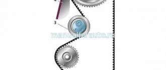
A drive gear meshes with the steering rack and is mounted in the crankcase on bearings. A stop made of cermet, sealed in the crankcase with a special rubber ring, presses the rack against the gear with a spring. The locking ring prevents the nut from unscrewing. The assembly of the assembly is facilitated by marks located on the boot and the steering mechanism housing.
| Cause of breakdowns | Remedy |
| The free play on the steering wheel has increased | |
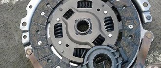
| The nuts securing the ball pins of the rods have become loose | The presence of a cotter pin is checked, the nuts are tightened and cotter pinned. |
| The clearance in the ball joints of the rods has increased | The rod ends are changed |
| The rubber-metal joints of the rods are worn out | New rods or rubber-metal joints are installed |
| There is a large gap between the nut and the rack stop | Worn parts are replaced and the steering mechanism is adjusted |
| Noise or knocking noise in the steering wheel | |
| The nuts of the ball joints of the rods are loose | Nuts are checked and tightened |
| There is a large gap between the nut and the rack stop | Worn parts are replaced, the steering mechanism is adjusted |
| The steering mechanism is loose | The nuts are tightened to fix the steering mechanism |
| The fixing bolt on the gear shaft of the lower flange of the elastic coupling has become loose | The bolt holding the lower flange of the coupling is tightened |
| Steering wheel turns hard | |
| Damaged upper suspension strut bearing | Replace the support assembly or bearing |
| Defective support sleeve or rack stop | New parts are installed, lubricant is added |
| The tire pressure on the front wheels has decreased | Normal pressure is established |
| Malfunctions in the parts of the ball joints of the rods | Damaged parts are replaced |
| Damage to elements of the telescopic suspension strut | Repairing or installing a new suspension strut |
| Damaged bearings on the upper steering column shaft | Bearings are changed |
| The column is not fixed in the desired position | |
| The adjustment lever pinch bolt turns | The lever with the adjusting sleeve is unscrewed from the bolt and the protrusion of the bolt is installed in the slot of the guide plate on the steering shaft bracket |
| The adjustment lever rests on the facing casing | The facing casing, lock washer, and lever are removed. The sleeve is tightened, the lever is put on in the desired position. The reliability of fixation and operability of the tensioning device is checked, the lock washer and the facing casing are installed |
Basic faults
Like any other mechanical structure, the steering rack, due to certain circumstances, may show signs of malfunction. These include:
- crunch (knock) when turning the steering wheel;
- “tight” steering wheel;
- increased play in the steering wheel or steering shaft drive gear;
- vibration of the steering shaft when driving;
- uneven tire wear caused by improper alignment of the front wheels.
The listed symptoms indicate that it is time to repair or replace the steering rack. However, do not rush into replacement. The rail itself is made of durable steel, and it is not so easy to damage it. Most often, auxiliary structural elements become unusable:
- support sleeve;
- drive gear bearings (ball and needle);
- seals;
- anthers, etc.
There can be any number of reasons for the failure of these parts, from spent resources to mechanical damage due to off-road driving. If you are sure that the rack itself will not have to be changed, you can get by with minor repairs to the steering structure, which consists of replacing the listed “consumables”.
How to repair a steering rack
If the steering rack on a VAZ 2112 car breaks down, repairs need to begin with the acquisition of materials, tools and spare parts. Materials:
- Grease for bearings. Preference should be given to Mobil Grease XHP 222.
- Movil in aerosol packaging.
- White Spirit.
- WD-40 can.
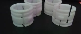
- Plastic clamps 200 mm x 4 mm.
- Rags.
- Ratchet socket wrenches.
- Cardan with extension.
- Hammer.
- Puller for removing tips.
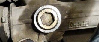
- The key is 22.
- Key with internal octagon.
- A chisel, its width is no more than seven millimeters.
- Steering wheel cover.
- Ends with nuts.
- Silent blocks.
- Repair kit for steering rack.
Work order
The instructions indicate that the work is performed on a well-secured vehicle. To do this, chocks are installed under the rear wheels, the handbrake is applied, and the steering wheel is locked.
Tip: To avoid troubles when repairing the steering rack, it is better to disconnect the battery terminals from the car.
- The front wheels are unscrewed.
- Using a special puller, the fingers are pulled out from the lever struts; before doing this, you need to unscrew the nuts of the tips.
- The puller is placed all the way, the screw is tightened. The finger is knocked out of the lever with a hammer, while the key is in a tense state.
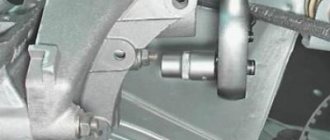
- The nuts securing the rack brackets are unscrewed. From inside the cabin, a bolt is removed from the steering shaft.
- Using an oscillating motion, carefully detach the gear shank from the steering shaft. You need to make sure that the splines on the part are not damaged.
- The entire assembly is pulled out through the right hole located in the car body.
- Before starting repairs on a VAZ 2112 car, the steering rack is clamped in a vice. Use a special brush or a cloth soaked in white spirit to clean all surfaces of the assembly.
- The steering rods are pulled out. The bolts on the bracket fixing them are unscrewed, the “tendrils” of the locking plate are bent, using a “22” wrench.
- The locking and connecting rods of the plate are removed.
- The steering rods are removed.
- The retaining ring and support are removed from the right side of the steering gear housing.
- The clamps securing the protective cover are cut off. The parts can be used once and are made of plastic.
- The protective cover is removed.
- The protective cap and support are removed from the left side of the assembly.
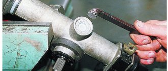
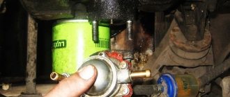
- Using a 17mm wrench, the nut on the rack stop is unscrewed, the element is removed, and the spring and retaining ring are pulled out.
The nut, spring and fixing ring are removed from the product
- The rack stop is knocked out of the socket. Carter needs to be hit on a wooden stand. The rubber ring is installed in the groove of the stop for sealing.
- The seal is removed.
- The gear boot is removed; just pry it off with a screwdriver.
- The lock washer is pulled out.
- Using a 24mm wrench, unscrew the nut securing the gear bearing.
- The nut is removed from the shaft.
- Using a “14” wrench, the gear is unscrewed from the crankcase simultaneously with the bearing.
The gear with the bearing is unscrewed from the crankcase
- The rack is pulled out.
- The bushing is removed. The support sleeve is pryed off with a screwdriver, its protrusions should fit into the holes located in the crankcase and then the part can be freely removed.
The support sleeve is removed
- A new bushing is installed. New rubber damping rings are installed on it so that the thin parts of the ring are located against the cuts in the bushing. The protrusions on the bushing should fit freely into the holes on the crankcase.
- The rings are cut along the edges of the bushing and the cut parts are thrown away.
- The fixing ring is removed from the gear shaft.
- Using a two-jaw puller, you need to compress the ball bearing as shown in the photo.
We repair it ourselves
If you have to repair the rail yourself, it is worth noting that this is a rather complex process that requires a certain skill and knowledge. Of course, DIY repairs will cost less . The work will also require the help of a partner.
Tools and consumables
Required:
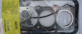
- Repair kit.
Steering rack repair kit
- Octahedron.
- Head at "15".
- Jack.
- Mount.
- Head at “10” and “13”.
- Lubrication.
- Parts cleaner.
Dismantling the rack on a VAZ-2112
We have already written in more detail about replacing the steering rack on a VAZ-2112.
First, you will need to remove the battery, the platform under it and the air duct in the engine compartment. Next, you will need to unscrew the clamps that secure the rail to the body. The difficulty of this work is that if you unscrew it carelessly, you can damage the studs , which are quite difficult to replace.
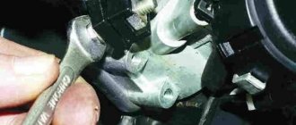
Removing the tie rod ends from the steering rack
After this, you should unscrew the bolts that hold the rod ends. Next, the flange bolt securing the rack is unscrewed. After this, you need to fold the rail away from the body. This will require a pry bar or crowbar. You can pull out the mechanism through the hole in the mudguard. A jack will be needed here.
Steering mechanism assembly with drive
1 – tie rod end; 2 – ball joint of the tip; 3 – rotary lever; 4 – adjusting rod; 5 and 7 – inner tie rod ends; 6 – bolts securing the steering rods to the rack; 8 – steering gear mounting bracket; 9 – steering gear support; 10 – protective cover; 11 – locking plate; 12 – connecting plate; 13 – rubber-metal hinge; 14 – damping rings; 15 – rack support sleeve; 16 – rack; 17 – steering gear housing; 18 – coupling bolt; 19 – elastic coupling flange; 20 – roller bearing; 21 – drive gear; 22 – ball bearing; 23 – retaining ring; 24 – protective washer; 25 – sealing ring; 26 – bearing nut; 27 – intermediate steering shaft; 28 – boot; 29 – protective cap; 30 – sealing ring of the stop; 31 – rack stop; 32 – spring; 33 – stop nut; 34 – retaining ring of the stop nut; 35 – plug; 36 – liner spring; 37 – ball pin insert; 38 – ball pin; 39 – protective cap; A, B – marks on the boot and crankcase; C, D – surfaces on the ball joint and swing arm
Steering column
1 – intermediate steering shaft; 2 – coupling; 3 – steering shaft mounting bracket; 4 – cardan joint; 5 – spacer sleeve; 6 – bushing of the support plate; 7 – universal joint crosspiece; 8 – needle bearing of the crosspiece; 9 – support plate; 10 – pipe of the steering shaft bracket; 11 – fixing plate; 12 – welded body bracket; 13 – steering shaft bearing; 14 – upper part of the facing casing; 15 – upper steering shaft; 16 – contact plate holder; 17 – steering wheel fastening nut; 18 – steering wheel; 19 – lower part of the facing casing; 20 – steering column position adjustment lever; 21 – retaining ring; 22 – tension spring; 23 – lever adjusting sleeve; 24 – coupling bolt; 25 – spacer sleeve
Steering parts
1 – inner tie rod ends;
2 – steering gear mounting bracket; 3 – steering gear support; 4 – spacer ring; 5 – steering mechanism; 6 – sealing gasket; 7 – thrust plate of the seal; 8 – seal; 9 – lower flange of the elastic coupling; 10 – intermediate steering shaft; 11 – coupling bolt; 12 – spacer sleeve; 13 – facing casing (upper part); 14 – upper steering shaft; 15 – steering wheel; 16 – signal switch cover; 17 – adjusting sleeve; 18 – steering column position adjustment lever; 19 – retaining ring; 20 – facing casing (lower part); 21 – steering shaft mounting bracket; 22 – steering shaft bearing; 23 – adjusting rod; 24 – outer tie rod end; 25 – spring ring; 26 – protective cover; 27 – sealing ring The steering is safety-resistant, with a height-adjustable (tilt-angle) steering column, and a rack-and-pinion steering mechanism.
The steering mechanism assembly with steering rods is attached in the engine compartment to the front panel of the body on its two brackets using brackets 8 (Fig. Steering mechanism assembly with drive). Fastening is carried out through rubber cushions (supports) with 9 nuts on welded bolts.
In the steering gear housing 17, a drive gear 21 is installed on roller bearings 20 and ball bearings 22, which meshes with rack 16. The inner race of the ball bearing is fixed on the gear shaft with a retaining ring 23, and the outer race is pressed with a nut 26 to the end of the bearing seat in the steering housing mechanism. There is a sealing ring 25 in the recess of the nut. A protective washer 24 is installed between the nut and the locking ring 23.
The nut is locked in the crankcase with a washer and covered with boot 28, mounted on the drive gear shaft. Marks A and B are made on the boot and on the steering gear housing to ensure that the steering gear rack is installed in the middle position. The rack 16 is pressed against the teeth of the drive gear by a spring 32 through a metal-ceramic stop 31, which is sealed in the crankcase with a rubber ring 30. The spring is pressed by a nut 33 with a locking ring 34, which creates resistance to unscrewing the nut.
A protective cap 29 is put on the steering gear housing on the left side, and a pipe with a longitudinal groove is pressed onto the right side. The spacer bushings of the rubber-metal hinges 13 of the internal tips 5 and 7 of the steering rods pass through the groove of the pipe and the holes in the protective cover 10. The steering rods are attached to the rack with bolts 6, which pass through the connecting plate 12 and the spacer bushings of the rubber-metal hinges 13. The bolts are secured with a locking plate 11.
The steering shaft consists of an upper 15 (Fig. Steering column) and an intermediate 1 shaft, connected to each other by a cardan joint 4. The intermediate shaft is connected to the drive gear by a flange 9 (Fig. Steering parts) through an elastic coupling. The upper shaft is located in pipe 10 of bracket 3 (see Fig. Steering column) on two ball bearings 13, which have elastic bushings on the inner landing diameter.
Bracket 3 for fastening the steering shaft is attached at four points to the welded bracket 12 of the body, and the front part of the bracket is secured through two fixing plates 11 with bolts with tear-off heads.
The rear part of the steering shaft bracket 3 is secured with welded bolts using nuts with or without spring washers and self-locking nuts.
Removal:
1) At the beginning of the operation, you will need to hang both front wheels from the car, for this operation you may need either one or two jacks (Just instead of one jack, you can also use logs), after the front part is hung, remove it from both sides of the car's wheel. (You can find out how to remove a wheel by studying the article entitled: “Replacing wheels on a car”)
Note! Don’t forget to stop the car with the handbrake just in case and put some more bricks under the rear wheels just in case!
2) Now you need to remove the adsorber if you have one, because it takes up quite a lot of space and if you don’t remove it, then there simply won’t be much access to the steering rack. (For information on how to remove the adsorber from a car, read the article: “Replacing a car adsorber”)
3) Then, in the very central part of the rack, unscrew the two bolts that are also indicated in the diagram above as number 10, which secure the tie rods to the rack, but keep in mind the fact that these bolts are also secured with lock washers, which you will need to bend back (You will see them immediately ), so that they do not interfere with unscrewing these bolts securing the rods to the rack.
Note! For ease of unscrewing, you can also move the steering wheel all the way in any direction, because when the steering wheel rotates, the rack also moves, and thus select exactly the moment when it will be easiest for you to unscrew these fastening bolts!
4) Next, climb into the cabin under the place where you have pedals installed and there look for the universal joint locking bolt (Indicated by the red arrow), if necessary, bend back part of the carpet (Carpet is what the floor of the car is covered with, before it didn’t exist, people replace it the styles themselves are linoleum, but this is in old cars, in new ones a carpet is used which covers the metal part of the body) if it will cover this bolt, but when you unscrew the bolt, insert a large screwdriver or a chisel into the groove indicated by the blue arrow and widen it so that the rack can be removed from the car.
5) Well, to complete the operation, unscrew the two (on each side) nuts that secure the rack to the car body, these nuts secure it in its outermost part, that is, on the left and, accordingly, on the right, and when they are unscrewed, then you can pull the steering rack towards you (this will remove it from the studs) and then remove it from the car.
Note! If it is not convenient for you to unscrew the nuts from the engine compartment, then you can, in the side part of it, in the place where you have a telescopic strut installed (the strut spring is indicated by a blue arrow), unscrew all these nuts (one of the nuts is indicated by a red arrow for clarity) securing the rack and then remove it from the car as well! (Pulling out the rack through the engine compartment is not very convenient, so try to pull it out through the cutout where the telescopic stand is installed, you can see this cutout in the photo below)
The telescopic strut spring is shown with a blue arrow and the rack mounting nut is shown with a red arrow.
6) Let’s add something else, usually new racks are initially sold assembled with steering rods, if you also have these rods for the racks (These rods, if you don’t understand what we’re talking about, are shown in the diagram and indicated by numbers 11 and 6) then in this case, you will have to remove the old rods from the car (the instructions are simply aimed at removing only the rack itself, and therefore we didn’t say anything about removing the rods at the beginning), if you don’t know how to remove them, then in this case, study the article entitled: “Replacing steering rods on VAZ 2109 cars.” (Don’t pay much attention to the VAZ 2109 brand, because the cars of the Samara and Samara 2 families are very similar to each other and therefore the rods are removed identically in both)
Installation:
The rack is installed in the same way as it is removed from the car, but only in the reverse order of removal.