To ensure proper operation, modern car engines are equipped with many different devices and controllers. If any of the elements cannot work properly, this may affect the functionality of the power unit as a whole. What are they used for and how to check the mass air flow sensor on a Gazelle and the lambda probe? We will talk about this below.
Characteristics and features of the mass air flow sensor
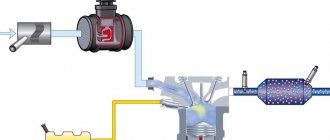
The mass air flow sensor is a hot-wire element. It is used to measure the volume of air flow entering the engine, which allows you to determine the required volume of fuel for injection. The device is mounted between the air filter and the throttle line.
The main task of the sensor is to maintain the temperature of the temperature-sensitive sensitive component at a certain level. In particular, we mean a thermistor made in the form of a platinum-iridium filament. More modern devices are considered film devices because they use a thread as a sensing element instead of a thread.
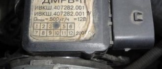
Mass air flow sensor for Gazelle car
This element must be heated to a set temperature, which must be higher than the ambient temperature. The air flow that passes through the filament in any case affects the dissipation of thermal volume. The larger the volume of air that enters the system, the better the cooling and the lower the temperature. Eventually, the level of resistance or temperature on the filament begins to change and in order to return it to its previous state, current begins to flow through the device. By the way, current can be used to determine the incoming air volume, but in fact it is not current that is used, but voltage.
Interchangeability
This issue is quite relevant, especially taking into account the cost of original products from the imported automobile industry. But it’s not so simple here; let’s give an example. In the first production models of the Gorky Automobile Plant, the injection Volgas were equipped with a BOSCH air flow sensor. Somewhat later, imported sensors and controllers replaced domestic products.
A – imported filament air flow sensor manufactured by Bosh (pbt-gf30) and its domestic analogues B – JSCB “Impuls” and C – APZ
Structurally, these products were practically no different with the exception of several design features, namely:
- The diameter of the wire used in a wirewound thermistor. Bosch products have a diameter of 0.07 mm, and domestic products have a diameter of 0.10 mm.
- The method of fastening the wire differs in the type of welding. For imported sensors this is resistance welding, for domestic products it is laser welding.
- Shape of a thread thermistor. Bosh has a U-shaped geometry, APZ produces devices with a V-shaped thread, and products from JSC Impulse are distinguished by the square shape of the thread suspension.
All the sensors given as an example were interchangeable until the Gorky Automobile Plant switched to film analogues. The reasons for the transition were described above.
Film air flow sensor Siemens for GAZ 31105
It makes no sense to give a domestic analogue to the sensor shown in the figure, since outwardly it is practically no different.
It should be noted that when switching from filament devices to film devices, most likely, it will be necessary to change the entire system, namely: the sensor itself, the connecting wire from it to the ECU, and, in fact, the controller itself. In some cases, the control can be adapted (reflashed) to work with another sensor. This problem is due to the fact that most filament flowmeters send analog signals, while film flowmeters send digital signals.
Possible controller malfunctions and ways to eliminate them
Several malfunctions may occur in the operation of the device:
- The sensitive element of the sensor - film or thread - is damaged. Typically, this problem occurs due to wear and tear. It is theoretically possible to repair such a regulator, but in reality it can take a lot of time and effort. Therefore, many car enthusiasts simply change the mass air flow sensor.
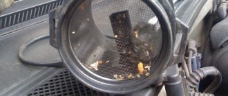
- The flow meter is clogged. This problem usually occurs as a result of prolonged use of the sensor. Clogging of the device, especially when constantly using the car in city mode, is a completely normal situation. The problem can be resolved by cleaning the flow meter or replacing it.
- Another malfunction is damage to the contacts or their oxidation. Damage can occur as a result of long-term operation of the flowmeter in vibration conditions, and oxidation can be caused by high humidity or long-term operation. In any case, you can try to repair the damage to the plug, but if that doesn’t work, the connector can always be replaced. As for oxidation, this problem can be solved by cleaning the contacts. An iron construction brush or a toothbrush can be used for this.
- Damage to wiring. It’s not exactly a malfunction of the flow meter itself, but if a break occurs in a section of the electrical circuit, the device may stop working. Accordingly, this will also affect the performance of the motor (the author of the video is the Simple Opinion channel).
If all else fails, buy a new air flow sensor
All testing methods showed the same result - “Sensor to be replaced.” The mass air flow sensor is quite expensive, and you should approach its purchase consciously.
Using the example of the same manufacturer Bosch for LADA and GAZ (article 0280218037) - according to the search results on the GisAuto portal as of September 18, 2022, 568 offers from different cities were found in Russia. The cost of this sensor varies from 2,490 rubles. up to 6,676 rub. Such a range in prices may depend on various reasons: availability, delivery time, purchase cost, etc.
You can select a mass air flow sensor for your car on the GisAuto portal - you can use the part number, make and model of your car, and also create a request using the VIN number of the car, and then the sellers themselves will send you their offers. All you have to do is choose the option that suits the price and time frame.
Source
Checking the regulator for functionality
Diagnostics of the flow meter is carried out using a voltmeter:
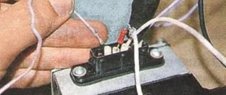
- First disconnect the battery. Use a screwdriver to pry up the spring clamp of the block, and then disconnect the flow meter plug.
- Use a screwdriver to loosen the clamps and remove them.
- Remove the controller, then install pieces of polyvinyl chloride tube onto the contacts of its connector.
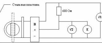
- Install the ends of the wires into these sections, as shown in the diagram, approximately 7-8 mm. When connecting, you should be guided by the profile of the end of the plug.
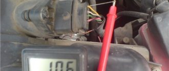
- Now you need to take the tester readings with the device switch turned off. If the controller is working properly, then the voltage level on its pins 2 and 3 should be about 1.3-1.4 volts.
- Then the switch should be turned on for a short time, while the tester readings are checked again. If the device is working properly, then the voltage value at its contacts should increase to 8 volts or around that. At the same time, you will notice that the sensitive element on the device (if it is a thread) has warmed up to red. If the diagnostics showed different values, then the flow meter must be replaced. The assembly procedure is carried out in reverse order.
Photo gallery “We check the mass air flow sensor ourselves”
Briefly about the renovation
As a rule, MAF sensors that have become unusable cannot be repaired, except in cases where they require washing and cleaning.
In some cases, it is possible to repair the volumetric air flow sensor board, but this process will not prolong the life of the device for long. As for the boards in film sensors, without special equipment (for example, a programmer for a microcontroller), as well as skills and experience, it is pointless to try to restore them.
Internal combustion engines in cars operate by supplying not only gasoline alone, but a combustible fuel mixture into the combustion chamber. The concept of fuel mixture refers to a certain amount of gasoline and air. If on the predecessors of the UAZ Patriot SUVs, air supply adjustment was the responsibility of the driver, now a special sensor known as the mass air flow sensor is responsible for this. The mass air flow sensor determines the required amount of air that is required to be supplied to the cylinders along with fuel. Thus, a malfunction of this device leads to improper operation of the engine, so you need to know how to troubleshoot the product, as well as troubleshoot and replace the product on a UAZ Patriot SUV.
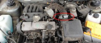
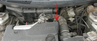
The mass air flow sensor on the UAZ Patriot SUV is a plastic pipe, the functioning of which is carried out by changing the value of internal resistance. Power is supplied to the sensor via wires. The product is located under the hood of the car after the air intake filter on the intake manifold between the air filter and the exhaust pipe. The photo below shows the location of the product.
UAZ Patriot SUVs are equipped with two types of mass air flow sensors type HFM5-4.7 with number 0280218037 from Bosch or mass air flow sensor from Siemens type 20.3855. The main purpose of the sensor is to determine the volume of air that passes through it. But, in addition, the mass air flow sensor allows you to determine the temperature of the incoming air, as a result of which the controller calculates the exact volume of air required to create the air-fuel mixture. The temperature of the incoming air is controlled by means of a sensor installed in
thermister. In the event of a product failure, the controller receiving the signals takes a fixed air temperature value of 33 degrees. The cost of the product is about 3000-5000 rubles, which depends on the manufacturer of the product. Let's look at the main types of malfunctions of the mass flow sensor on the UAZ Patriot SUV.
Types of faults
A faulty mass air flow sensor leads to disappointing consequences, so it is very important to ensure its performance. Malfunctions of these devices may manifest themselves in the following ways:. What does the sensor consist of?
What does the sensor consist of?
- The first factor indicating a malfunction of any element on the car is the illumination of the Check Engine indicator.
- At the same time, an increase in fuel consumption is observed.
- The UAZ Patriot car cannot be started after the engine has warmed up.
- While the car is moving, the driver can feel the UAZ Patriot “stupid”.
If the above symptoms are detected, you should immediately proceed to correct the breakdown. To do this, the first step is to remove the mass air flow sensor and inspect it. Let's look at what the process of removing the mass air flow sensor on a UAZ Patriot Euro-3 SUV is like.
Removal and replacement
The process of removing the product is not difficult and does not take more than 10-15 minutes. All you need to remove the sensor is a 10mm wrench and a Phillips screwdriver. The first step is to de-energize the car by removing the negative terminal from the battery. After this, we proceed to the direct process of removing the sensor from the UAZ Patriot SUV:
Disconnect the hoses from the sensor
- From the bottom of the device, you need to press the plastic clamp of the terminal block and remove it from the sensor.
- Next, loosen the clamps using a Phillips screwdriver.
- Now you can remove the rubber pipes from the product and remove the released element.
This is actually the mass air flow sensor of the UAZ Patriot SUV Euro-3 and Euro-4. After removal, you can check its serviceability. How the mass air flow sensor is checked is discussed below. If this device becomes unusable, it must be replaced with a new part. The process of installing the mass air flow sensor on a UAZ Patriot SUV is performed in the reverse order of removal.
Description of the oxygen sensor
A lambda probe or oxygen sensor is mounted in the Gazelle exhaust system. This device is used to measure the volume of oxygen in exhaust gases. By design, the device is equipped with a built-in heating element, which allows you to quickly warm up the controller to ensure its normal operation. The readings taken by the lambda probe are used to adjust the fuel supply, check the condition of the engine, as well as the exhaust gas neutralization system.
Sequence of actions when calling
- Before you test the circuit with a multimeter, you need to turn the handle of the device to the desired position.
- Install the ends (measuring leads) into the appropriate sockets. The black wire goes into the socket marked COM (sometimes it can be marked with “*” or a ground sign), and the red wire goes into the socket where the Ω sign is indicated (sometimes it can be marked with an R sign). It is worth noting that the Ω sign can be applied either separately or in combination with the designations of other units of measurement (V, mA). This is the correct position of the test leads, which will allow you to maintain polarity when making further measurements. Although if only the integrity of the wires is checked, their relative position will not affect the result obtained.
- Turn on the device. A separate button may be provided for this, or activation may occur automatically when the knob is turned to the desired position when selecting measurement limits or operating modes.
- Connect the measuring ends to each other. If a signal sounds, it means that the device is operational and ready for use.
- Take the cable or wire being tested (its ends must first be stripped of insulation, stripped to a metallic shine, and dirt and oxides removed from the surface). Touch the test leads to the exposed areas of the conductor.
- In case of continuity, a signal will sound, and the device readings will either be 0 or indicate the resistance value. If the display shows 1 and there is no beep, the tested conductor is broken.
https://youtube.com/watch?v=EIyKzTBhyBA
https://youtube.com/watch?v=EIyKzTBhyBA
Possible controller malfunctions
The following errors may indicate device malfunctions:
- P0131, P0132. These errors indicate that the signal level from the oxygen sensor is too low or too high.
- P0134. The control unit did not detect the activity of the lambda probe.
- P0135. This error may indicate an open circuit connecting the sensor, as well as a possible short to power or ground.
- P0133. Controller response is too slow.
- P0137, P0138. Very low or high signal from the second lambda probe.
- P0141. The malfunction also concerns the second oxygen sensor, in this case we are talking about an open circuit or short circuit (the author of the video is the Lty D channel).
Drive unit
Drive shaft, CV joint (grenade), Outer CV joint, Inner CV joint, Right CV joint, Left CV joint, CV boot, Tripoid, CV joint nut, Retaining ring, Cardan, Crosspiece, Suspension bearing, Cardan bearing, Elastic coupling, Axle, Front axle, Rear axle, Axle reducer, Gearbox bearing, Gearbox oil seal, Differential, All-wheel drive sensor, Haldex coupling, Differential bearing, Differential oil seal, Planetary gears, Axle bearing, Axle shaft, Axle shaft bearing, Axle oil seal, Axle shank, Shank bearing, Axle bearing, Transfer case, Transfer case, Transfer case oil seal, Transfer case bearing, Transfer case chain
Source
Checking the regulator for functionality
Diagnostics of the oxygen sensor is carried out as follows:
- First, the device must be inspected. If visual diagnostics made it possible to identify defects in the device, then most likely it was the damage that caused its failure. If so, then the device changes.
- If the error shows an open circuit, then you need to try to find a break in the wiring or damage to the electrical circuit.
- Disconnect the device from the power connector, perform a visual check of both plugs - the sensor itself and the connection circuit. If there are traces of rust or deposits or oxidation on the connectors, you can try to clean them. If the marks are strong and cannot be cleaned off, or if you damaged the contacts while cleaning, they should be replaced.
- If these steps did not help you identify problems, then you will need a tester to proceed further. Get your multimeter ready, reconnect the sensor, start the engine and warm it up to operating temperature, then turn it off.
- Then the oxygen controller will need to be disconnected from the connector again, after which it will connect to the tester.
- The car engine starts again, now you need to sit in the driver's seat and press the gas to increase the speed. The revolutions should be kept around 2500 per minute.
- Look at the multimeter screen - if the value is close to 0.9 W, this indicates that the lambda probe is in good condition and does not require replacement. If the readings do not rise above 0.8 W, this indicates the need to replace the regulator. Then all you have to do is dismantle it and replace it with a new one.
Communities › GAZ Volga › Blog › How to check the mass air flow sensor? High speed XX
Is it possible to check it using a tester, without a special scanner?
I wrote about the rich mixture in the previous topic.
Another confusing point is that the idle speed on a warm engine, according to the tachometer on the dashboard, is about 1100 rpm.
If I understand correctly, then they should be about 900 +/-?
Tags: dmrv, xx zmz 405, xx mikas 7.1
Comments 25
The damper may have worn out.
Thin throttle assembly. What does the DMRV have to do with it? If it fits into the standard parameters, what are the claims against it? The air conditioner flag raises xx. And adaptation rrx, but this is exotic. Try turning the throttle stop slightly towards the cover. Well, everyone has already talked about the IRR pipe without me here.
Standard idle speed 850 +- 50. More often closer to 850 rpm
The easiest way is to pinch the pipe going to the IAC with your fingers. The car should stall. If this is not the case, then watch the air intake. If it stalls, remove the terminal from the damper position sensor. The idle should fall. If this does not help, then you can remove the IAC and see its condition (ring the windings). The stepper motor rotor should rotate easily and not jam. And it’s trivial to check whether the throttle cable is tight (there should be a slight slack on the cable)
By squeezing the pipe on the IAC it stalls. The throttle cable is not tensioned, there is some slack.
I'll try to remove the connector on the damper!
If the IAC stalls, it means there is no suction. I should go deaf at once and not convulse for a long time. If you have an ohmmeter, try checking the throttle position sensor. I think the dog rummaged through it. Before all this, was the car gradually picking up speed or with a jerk in the bottom? And watch the IAC itself so that the rotor rotates easily from a slight rocking of the housing...
IAC is new, only 3 months old. But then I checked and rotated. About a smooth climb or jerks in the lows... didn’t understand the question?!
If it’s cold, it starts with difficulty (without the gas pedal), but it responds adequately to the pedal. When starting, the revs do not jump or jerk. It just wobbles, almost stalls due to the rich mixture, but it works...
when the engine is warmed up, the speed rises smoothly, or there is a “step”, say 1500-2500 rpm
No, smoothly (if we are talking about the response to the gas pedal?!)
Yes, exactly about her. This means that the likelihood that this is TPS is minimal. Of course you can check, but it’s unlikely. It has the following parameters - 1. Power supply voltage (pins 1-2): 5.0+0.1V 2. Resistance between pins 1-2: 1.8...2.0 kOhm 3. Opening degree of a fully closed choke: 0...2 % 4. Voltage (pins 3-2) with a closed choke: 0.25...0.65V 5. Opening degree of a fully open choke: >90% 6. Voltage (pins 3-2) with a full throttle: 3.90...4 ,70V 7. Number of complete response cycles: at least 1 million cycles 8. The calibration characteristic of the dependence of the sensor output voltage on the rotation angle is linear in the range 0...100° (0.25...4.8 V). The slope of the characteristic is 48 mV/°. 9. The working area of the sensor is in the linear characteristic range of 10...90°, which corresponds to the degree of throttle valve opening in the range of 0...100% throttle opening. The slope of the characteristic is 39 mV/%.
Thank you! I'll try to check it out too! Just a question: what is the voltage at the terminals? Do I need to unplug the connector and apply power there? Am I not very good at this?!
No, when the sensor is connected, you measure the voltage. Thin probes are needed. Run it along the wire until you get to the “mother”. The pinout is most often indicated on the block by numbers.
Tags: zmz 406
Comments 26
My consumption at XX is generally 0.9-1) Thanks DBP) But in general, the normal consumption for the mass flow sensor is 1.2. If it is too high, it means that the injectors are not topped up, the injectors open more strongly, and from here the instantaneous flow rate is taken based on the opening time. It's either the injectors or the fuel pump. In general, it would be flashed for 580 at least. In terms of temperature - well, it’s not at work. It should be approximately above 80 for various corrections to cease to apply. For 406, the normal temperature is 87 where RCOD RCOK - suspiciously the same - set it according to the gas analyzer. Leave the correction at -2 if you drive at a good 92m. I drove the 95 at -5
I just measured these parameters at 80. and so the fan on 87 turns on. 580 how to flash? Are there any pitfalls? MAF Siemens 20.3855. you need to look at the markings exactly. RCOD RCOK approximately what should they be? Are they exposed to a hot internal combustion engine?
Only the gas valve at operating temperature will tell you approximately; if it is not there, I recommend setting it to zero.
It's not difficult to flash, do you have an adapter for diagnostics? I can upload the firmware slightly corrected
I know how to flash it, and I corrected the old firmware in the fuel supply mode at start-up. otherwise it flooded from -5 degrees and below.
Then there is no reason to worry at all - feel free to upgrade to 580
My consumption at XX is generally 0.9-1) Thanks DBP) But in general, the normal consumption for the mass flow sensor is 1.2. If it is too high, it means that the injectors are not topped up, the injectors open more strongly, and from here the instantaneous flow rate is taken based on the opening time. It's either the injectors or the fuel pump. In general, it would be flashed for 580 at least. In terms of temperature - well, it’s not at work. It should be approximately above 80 for various corrections to cease to apply. For 406, the normal temperature is 87 where RCOD RCOK - suspiciously the same - set it according to the gas analyzer. Leave the correction at -2 if you drive at a good 92m. I drove the 95 at -5
hi, I accidentally came across your comment. Similar shit is happening to me, but I didn’t find any answers, and your comment seems to be close to me... I have 1.4-1.5 on the xx, but sometimes with the tank filled more than half you can see 1.2-1.3 in traffic jams. There is no traction... the engine you accelerate... you get this feeling when you are driving at lower speeds. And there is no carbon deposits on the spark plugs; on the contrary, they are slightly white. Like when depleted. In the summer I changed the throttle, and the spark plugs eliminated the leaks in the engine for a while so I didn’t feel the weight of the car. Like a feather. And then somehow it started to work again... now I’m thinking about the injectors to clean them individually at the stand. Do you think this will increase the filling of the cylinders or should I look elsewhere? I was in diagnostics, the pump presses normally, the phases are not knocked down, the injectors are not clogged. but for some reason on their computer the hourly consumption shows 1.2 and my onboard one is 1.4-1.5
source
Rules for safe calling using a multimeter
testing the network cable with a multimeter
Working with electricity does not allow for unprofessionalism, so a certain list of rules has been developed that make it possible to make it as accurate, fast and safe as possible.
When making calls, it is most convenient to use special tips at the ends of the measuring wires, which are more commonly known as “crocodiles”. They will make the contact stable and free your hands when taking measurements. When testing, the circuit being tested must always be de-energized (even low-current batteries must be removed). If there are capacitors in the circuit, they must be discharged by short-circuiting
Otherwise, the device will simply burn out during work. Before checking the integrity of a long length of conductor when taking measurements, it is important not to touch its bare ends with your hands. This is due to the fact that the resulting readings may be incorrect.
When testing a multi-core cable, it is necessary to separate and strip all existing cores from both ends. After this, you need to check the circuit for the presence of short circuits in it: to do this, a “crocodile” is attached to each core in turn, and all the remaining ones are touched with the other measuring end in all possible combinations.
Check to see if there is a short circuit between the cable cores. If the indicator shows “1” and there is no sound signal, then everything is in order, otherwise there is a short circuit.
In this case, a sound signal will indicate the presence of a short circuit between the tested conductors
This may not be of practical importance for small cross-section multi-core cables operating in low-current networks, but when working with high voltages it is fundamentally important
We call the cable cores. There is a sound signal - everything is fine, otherwise the core is damaged.
To determine the integrity of the cores, the same operation is performed, only at one end of the cable all stripped cores are twisted together
When searching for a break, it is important to consider that the absence of a sound signal at either end will indicate a violation of the integrity of the conductor