Diagram, procedure for connecting VAZ high-voltage wires.
First, let's decide which of the four cylinders is first?
The first cylinder in front-wheel drive VAZs is located closer to the timing belt. If you look at the engine from the front, the first cylinder is the leftmost). And then everything is simple - from left to right - 1, 2, 3, 4.
In rear-wheel drive VAZ Classic and Niva, the first cylinder is located closer to the front bumper of the car.
Description
Collapse
Set of blue ø 7mm wire with resistive core, sheath made of SILIKON material, suitable for temperatures from -40 to +220°C
5 pieces. in stock
634.49 R
Buy in 1 click
Delivery
Pickup: 0 days
Delivery in Moscow: 1-2 days Free delivery from 5000 rubles.
Delivery to regions: 3-15 days Free delivery to shopping center from 5000 rub.
All delivery methods
Delivery methods and costs
Pickup from a warehouse in Moscow: free (0 days)
Courier delivery in Moscow and the Moscow region: 350 rub. (1-2 days) Free for orders over RUB 5,000.
Delivery to the regions by transport company: according to TK tariffs (3-15 days) Free delivery to TK from 5,000 rubles.
General tips for connecting high-voltage wires.
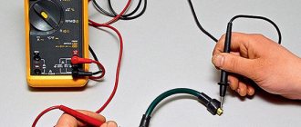
Checking high-voltage wires. To check the wires, you will need a multimeter tester. Check the resistance of the wires - it should be no more than 20 KOhms (in practice, the longest wire of cylinder 1 has a resistance of up to 10 KOhms). If the wire resistance is more than 20 Kom, it must be replaced. Carefully inspect the wires for chafing on parts of the motor or other wires. In case of significant abrasion, replace the wire. In case of minor abrasion, it is possible to lay the wire so that it does not rub and fix it in this position.
Laying wires. Do not try to connect the wires in a bundle. Disassemble the wiring harnesses, release the wires from the plastic holders. Connect the high-voltage leads to the corresponding cylinder spark plugs. Lay the wires so that they do not rub against each other, engine parts, or hoses. Avoid sharp bends and tension on the wires. After connecting all the wires, secure them into the bundle with special comb holders included in the delivery kit.
The procedure for connecting I/O wires to a VAZ carburetor (2108, 2109, 21099)
The central wire from the distributor cover always goes to the ignition coil (bobbin).
The outlet of the distributor cover, which faces towards the front of the car, is connected to the first cylinder.
The outlet of the distributor cap, looking down, is connected to the third cylinder.
The outlet of the distributor cap, looking rearward, is connected to the fourth cylinder.
The outlet of the distributor cap, looking up, is connected to the second cylinder.
The procedure for connecting high-voltage wires to a VAZ Classic, Niva with a carburetor and distributor.
Central wire from the ignition coil (bobbin)
1 cylinder - above the vacuum corrector. Next, clockwise, the order is 1-3-4-2.
Injection VAZ produced before 2004 with an old-style ignition module (4-pin low-voltage connector)
Actually, on the module body it is already indicated which cylinder the pins correspond to - but we duplicated them in red in case the module gets completely dirty, and you might not be able to see it in the photo.
Injection VAZ produced after 2004 with a new ignition coil (3-pin low-voltage connector)
As with the old-style ignition modules, the new coils are also marked with pins corresponding to the cylinders. But the connection order is different from the order on the old-style ignition module. Be careful.
Source
How often should GDP be changed?
According to the recommendations of Avto-VAZ, replacement of high-voltage wires of the VAZ 2114 should be done every 30 thousand kilometers. In practice, motorists rarely comply with these replacement deadlines, since if the wires do not have any mechanical damage, they can travel about 100-150 thousand km.
This operation will take you no more than 15 minutes:
- Turn off the ignition;
- We remove the wires: disconnect the first end from the ignition module, the second from the cylinder;
- We switch the tester to ohmmeter mode and connect the multimeter probes to the wire contacts.
If the high-voltage wires on the VAZ 2114 are in normal technical condition, the multimeter will show a resistance within the value indicated on the wire insulation; if the readings are different, the armored wires on the VAZ 2114 need to be replaced. The process must be repeated on each wire in turn.
If the test shows disappointing results, there is a possibility that the problem of increased resistance lies in oxidized contacts. In this case, you can try to revive the VVP by wiping the contacts with VD-40 or carburetor cleaning fluid.
Problems with ignition can be a breakdown of GDP. You can determine it visually in the dark - take a flashlight and open the hood of the fourteenth, find and inspect the armored wires, if you notice a slight spark on the insulation - the air intakes are broken and need to be replaced.
Hello subscribers,
I continue to look for the reasons for minor problems in the startup and operation of my engine.
After checking the resistance of the wires and their apparent serviceability, they still seemed somehow suspicious to me. A couple of months ago, I went for diagnostics to the injector specialists who have been servicing me since I bought the car. Part of the diagnostic procedure was connecting explosive wires to the sensors of a special oscilloscope. The oscilloscope drew beautiful resonant pictures (sorry, I didn’t take a photo), then there was a test of “spraying the wires with a spray bottle.” No sparks appeared visually, but the pulse shelf began to shift to the side. As they explained to me, this is the initial stage of the wires shooting outward. So far it can only be seen on a signal amplified by an oscilloscope, and based on some subjective sensations. But the process will progress. It was decided to replace them anyway.
The wires chosen were Bremi 233/200
, especially since my old wires were also
Bremi
.
But here’s the problem: on the old wires there are full markings, and that they are Bremi, and the resistance of the tips, and the numbering by cylinder and model number.
Numbering of wires by cylinders
Wire markings, lug resistance
And on the new wires, except for the orange caps and only on two wires - there’s nothing more!
These are the unnamed wires with two orange caps, one to one
And you think to yourself: what the hell was wrong with marking the wires?
Well, it would be okay if I weren’t a technical support engineer with the ensuing professional deformation of my personality.
Reminder for ACK drivers about replacing high-voltage wires
I decided to do it for myself, and maybe it will be useful to someone else, for those who decide to repeat my feat on the same motor and on the same wires.
We have the length of wires, both old and new: - the total length of the tips on one wire is about 8 cm; — to make it easier, I measured from tip to tip.
We measure the old wires and get the following numbers (numbers are given in cm, and in parentheses the total length with tips):
1 = 35 (43) 2 = 37 (45) 3 = 41 (49) 4 = 37 (45) 5 = 41 (49) 6 = 40 (48)
Picture with additional information on Bremi 233/200 wires
The second number after the fraction is similar to the length in centimeters. I don’t know from what point this length was measured, but a certain relationship with what we have already measured is visible (a difference of one centimeter):
1 = 42 2 = 44 3 = 48 4 = 44 5 = 48 6 = 47
Well, this is actually our map of wires, where to put what length.
The actual length of the wires, of course, differs from the given one, but they are longer by the same amount (about 4-5 cm offhand), and in principle you can select the wires according to their length. I did it a little simpler: I removed the wires one by one and selected them according to length so that they differed by the same amount. The first wire is the shortest, you can't go wrong.
We have more or less figured out the length of the wires. Now you need to learn which coils to connect where.
In the diagram it looks something like this:
Connection diagram of high-voltage wires to coils for ACK engine
But in general, a fairly simple algorithm is obtained verbally:
The front coils (which are closer to the belly, standing near the hood :)) go to the right head, which is also the first bank. Numbered from left to right in the direction of travel of the vehicle.
The rear coils go to the left bank, which is also the second bank. It’s easy to compare them: - 1st cylinder sits with the 6th (last); - The 2nd cannot be with the 5th, because they are paired, which means he is sitting with the 4th; — well, the 3rd cylinder gets the 5th cylinder in a pair :)
Dad figured out another verification algorithm. The cylinder sequence is written on the left valve cover: 1-4-3-6-2-5 Result
I changed them and drove home, and somehow didn’t pay attention to anything (to be honest, I was upset about the generator, but more on that later). Then I’m driving the next day, stopped at a traffic light, thought about it, hands on the steering wheel. And I feel that the vibration on the steering wheel is not the same as before. It has become smooth and balanced, there are no strong beats, the motor just works, clearly, softly and evenly. During acceleration, the vibration also became somehow softer or something, as if we had gone through it with fine sandpaper and removed sharp corners and burrs, a very pleasant feeling from the operation of the engine.
The wires were changed for a reason, and it should have been done earlier, perhaps my failures in the cold would have disappeared.
That seems to be all...
Helpful comment from
3JIo6HbIu:
the orange caps are tip removers, if you remove it, and then put it on perpendicular to the tip (I said it clumsily, I agree) and put your finger through the ring - it turns out that pulling off the tips is very easy)) I had the same ones on my Audi, I barely had my fingernails didn’t leave it on these tips, and then moved the convolutions - hell, I have a tool!
Price: $80 Mileage: 377,000 km
Automotive high-voltage (HV) wires play an important role for internal combustion engines, since they help transmit high current from the ignition coil to the spark plugs. The serviceability and efficiency of the wires determines the timeliness and intensity of ignition of the fuel-air mixture, and therefore the correct and uninterrupted operation of the engine. Despite their simplicity, wires have many different “sores” and can cause a lot of troubles to their owner, which in one way or another will affect his nerves and pocket.
Connection
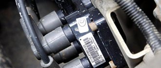
The order of connecting high-voltage wires must be strictly sequential, since each cylinder of the engine corresponds to a specific socket on the ignition module. Considering that there is a numbering of the sockets on the ignition module body, the risk of confusing anything is minimal.
The procedure for connecting high-voltage wires of the VAZ 2114 injection type depends on the year of manufacture of your car. Fourteen cars before 2004 had 4-pin ignition modules installed, and cars after 2004 had 3-pin coils.
The connection diagram for VAZ 2114 high-voltage wires to the ignition module (until 2004) is as follows:
Connection diagram for VAZ-2114 with ignition coils (after 2004):
In the pictures you can see the numbers of the landing slots. Each number must have a corresponding cylinder connected to it (cylinder numbering is counted from left to right).
To correctly install high-voltage wires on the VAZ 2114, follow the following algorithm of actions:
— Turn off the ignition. Open the hood and remove the power terminals from the battery;
— We remove the old GDPs from the mounting sockets on the module and cylinders;
— We remember the location of the high-voltage wires of the VAZ 2114 and connect new GDPs according to the diagram. Before replacing, it would not be amiss to draw this very diagram by hand on paper so as not to confuse anything;
— We connect power to the battery and, to check whether we did everything correctly, start the engine.
When installing the wiring, do not try to connect individual air intakes to each other with plastic clamps; to do this, you must use the comb holder that comes with them. A thin clamp can easily wear through the insulating coating. Also make sure that the GDP does not bend.
Connecting armored wires on VAZ 2115 and 2113 is carried out in a similar way.
Replacement
How to remove high-voltage wires?
Turn off the ignition. Open the hood. Pull out the wires from the ignition module and from the engine.
How to connect high voltage wires?
The BB wires must be connected in a certain order. Each wire goes to a specific cylinder and to a specific connector in the ignition module (ignition coil). There are markings both on the wires and on the ignition module. But without removing the module, the markings cannot be seen, so see the photo below.
Connection diagram for high-voltage wires:
Cylinder numbering from left to right. Ignition module numbering: first cylinder - lower left compartment of the ignition module
Second cylinder - upper left compartment
The third cylinder is the upper right,
The fourth cylinder is the lower right compartment of the ignition module.
Purpose
The high voltage wires in a vehicle are designed to carry high voltage from the ignition coil to the spark plug. The wire is a kind of connecting link between the spark plugs and the ignition module. Each spark plug has its own wire connected, which is phased with a coil or distributor. In the carburetor version of the VAZ 2107 engine, 5 pieces of high-voltage wires are used, 4 from the distributor to the cylinders and 1 from the coil to the distributor. In the injection version of the engine, only 4 wires are used from the ignition module to the spark plug.
Causes of damage
There are few of them and for the most part they are natural:
- Aging - due to constant temperature changes and engine vibrations, the insulation gradually wears out, after which it is easily broken through. The same applies to the attachment points to the spark plugs. The core itself also wears out naturally due to the constant supply of high voltage.
- Damage occurs most often due to repairs. That is, the mechanic either severely snagged the wire during the repair process, damaging it, or replaced the wires incorrectly altogether. They are specially located separately and do not touch other engine parts. If you place them differently, they will be damaged at least by a hot internal combustion engine.
- Other malfunctions - most often associated with a broken ignition coil, which causes more power to be supplied to the wires. Neither the wires nor their insulation are designed for this, so penetration occurs.
Device
Wires are made of material that has good insulation resistance, and the conductor of the wire should have low resistance for better conductivity of voltage and current.
A high-voltage wire has: insulation, a conductor, insulating caps and contact terminals. Also, some wires are equipped with a special comb, which is needed to assemble the wires into one unit.
Symptoms of a problem
Quite often, wires fail, which significantly affects the operation of the car engine. If the high-voltage wires fail on the car, the following signs of malfunction are observed:
- The car starts to move jerkily;
- When you press the gas pedal, the car jerks;
- One or even several cylinders fail;
- Engine power is lost;
If your car shows such signs of malfunction, it is recommended to check the high-voltage wires.
Checking wires
Checking the wires is done in two ways: visual and tester. To carry out a visual inspection, simply remove the wire and inspect it externally. The wire should not contain:
- There should be no cracks or signs of wear;
- Traces of rubbing of insulation;
- The cap must be in excellent condition without cracks;
- The contact part must be clean and free of rust;
- The wire must be clearly fixed on the spark plug and MH (distributor);
If the wires have visible damage, it is recommended to replace them.
Testing with a tester consists of measuring the resistance between the contacts; a working wire will show a resistance above 1 kOhm, but this does not mean that the wire is ideal, it is just working. New high voltage wires from some companies can show resistance as high as 10k ohms, but it should be noted that the shorter the wire, the less resistance it has and vice versa.
If, when measuring resistance, the tester shows 1, then this means a break and the wire is faulty.
Which GDPs are better to choose?
When choosing a GDP, two key factors must be taken into account - their resistance and breakdown voltage. The lower the resistance, the better the electrical impulse will be transmitted, and the magnitude of the maximum breakdown voltage determines how resistant high-voltage wires will be to breakdowns.
The resistance value of products from different manufacturers differs from each other. As an example, we give you the resistance of the most popular types of GDP:
The products of the Czech company Tesla receive the largest number of positive reviews from the owners of the fourteenth. Their wires have optimal resistance and high breakdown voltage, and at the same time they are truly made to last - they do not tan or crack.
The cost of the Tesla GDP set is about 500 rubles, Cezar - 450 rubles, Ween - 270 rubles, Finwhale - 600 rubles, Slon - 500 rubles.
Wire selection
Many people face a problem when replacing wires, and it’s hard to say which company to choose, which one is better, but new wires are always better than old ones, so you need to evaluate your capabilities strictly by the thickness of your pocket. The price range for high-voltage wires is quite large.
The most popular brands of high-voltage wires are SLON, AvtoVAZ, TESLA, these brands have proven themselves well and are in good demand.
Connection diagram for high-voltage wires (armored wires) VAZ 2107
When replacing wires, many are faced with the problem of connecting the wires to the spark plugs. Why is this so important?! If you connect the high-voltage wires incorrectly, nothing bad will happen, but the car will either not start, or it will start but will work extremely unstable.
VAZ 2107 armored wires have strict connection rules and must be observed. The number of cylinders in the “seven” starts from the timing mechanism (from the radiator), that is, the spark plug, which is closer to the radiator, is responsible for 1 cylinder, etc.
Injection engine
Connect the high-voltage wires of the injection engine in the following order. The ignition module has numbers with the cylinder number, these numbers can be seen in the picture, the number on the module corresponds to the cylinder number, and the wires must be connected in that order.
Carburetor engine
As you know, a carburetor engine does not have an ignition module, but instead has a distributor and one ignition coil. High-voltage wires in such an engine are connected in the following order. The central terminal of the distributor; the ignition coil is connected to it through a short high-voltage wire. The following wires are connected to the distributor terminals on one side and the spark plugs on the other side. The wires should be connected as shown in the picture.
Installing an electronic BSZ instead of a contact one
Today it is very rare to find a “seven” with contact ignition. With the arrival on sale of switches, distributors and coils for electronic spark generation systems, owners of classics began to massively re-equip their cars.
What is included in the BSZ kit
The process of converting a contact system into an electronic one is quite simple, and also inexpensive. The cost of an electronic ignition kit for a VAZ 2107 is about 2,500 rubles. It includes:
- transistor switch type 3620.3734 with connector;
- coil 27.3705;
- contactless distributor type 38.3706;
- connecting wires.
In addition, you will need spark plugs (preferably new ones) with a gap of 0.7–0.8 mm and a set of high voltage wires. Coil type B-117A (used in a contactless system) is not suitable for electronic ignition. Its characteristics do not correspond to those of other equipment in the circuit.
Video: review of BSZ elements for “classics”
Required Tools
To complete the work you will need:
- 8, 10 and 13 mm wrenches;
- screwdriver with a Phillips blade;
- drill;
- spark plug key;
- 36 mm wrench or with a ratchet mechanism for turning the crankshaft;
- self-tapping screws;
- pliers.
- Disconnect the terminals from the battery. We remove the battery and put it aside.
- Remove the high voltage caps from the distributor cap and from the spark plugs.
- Using a special wrench, unscrew all the spark plugs. We screw new ones in their place.
- Using a drill, drill holes on the left mudguard or on the engine shield to mount the switch.
- We attach the switch to the car body using self-tapping screws.
- Remove the distributor cap.
- We rotate the crankshaft, placing a wrench on the nut securing its pulley, until the distributor runner is aimed at the spark plug of the first cylinder, and the mark on the pulley points to the middle ebb on the timing cover.
- Using a 13 mm wrench, loosen the distributor mounting nut.
- Remove the vacuum hose from the distributor and disconnect all wires.
- We remove the old distributor from its seat.
- Remove the cover from the new distributor.
- Trying it on in place of the old one, we rotate the slider by hand until it is directed towards the first cylinder.
- We install a new distributor, tighten the nut, but do not tighten it completely.
- We connect the wire connectors and the vacuum regulator hose to the new distributor.
- We dismantle the old ignition coil by unscrewing the nuts securing it with a 13 mm wrench. We disconnect all wires from it.
- We install the new coil in place.
- We connect the connector with the wiring harness to the switch.
- We clean the ends of the wires. We install the chain:
- We securely attach the black wire from the switch to ground using a self-tapping screw or screw;
- connect the red wire to terminal “K” on the coil. We also attach the brown wire from the tachometer here;
- connect the blue wire from the switch and the blue wire with a black stripe to the “+B” terminal on the coil.
- We install the distributor cover and secure it. We connect new high-voltage wires to the cover and spark plugs.
- Let's try to start the engine. If it works, then everything was done correctly. Otherwise, we check the ignition circuit and the reliability of the connection of its elements.
Introduction
High-voltage wires of VAZ cars are one of the most important elements in the ignition system. It is the wires that transmit high electrical voltage from the module to the spark plug.
Failure of the wires affects not only the formation of a spark, but also the operation of the entire power plant. This article will talk about how to correctly select and independently replace high-voltage wires on a VAZ car.
Below we discuss the procedure for connecting wires to the ignition module, as well as examples of the highest quality and best wires that can be purchased in terms of price and quality.
Replacement
How to replace high-voltage wires on a VAZ 2107 can be seen in the video below.
Recommended viewing:
- Sensors VAZ 2107
- All about the water pump VAZ 2107
- Trouble VAZ 2107 engine: Cylinder failed
- DPKV VAZ 2107: Malfunctions, Check, Replacement
- Fuel pump for VAZ 2107: Checks and malfunctions
- Why does the VAZ 2107 have unstable idle speed?
Category: Personal experience
← Why the VAZ 2107 has unstable idle
Fuel pump for VAZ 2107: Checks and malfunctions →
Operating principle and device
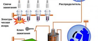
High-voltage wires are the link between the coil (ignition module) and the spark plugs. The voltage generated in the ignition module is transmitted to the spark plug through a high-voltage wire, after which the spark plug produces a spark in the combustion chamber of the internal combustion engine.
The wires have powerful insulation that can withstand enormous voltages without breakdown of the insulation. People quite often hear the name armored wire; high-voltage wires received this name because of their powerful insulation.
Device
A high-voltage wire consists of a core (also a conductor) placed in powerful shielded insulation. The core in the wire is shielded to preserve the voltage pulse from external influences and protect against breakdown.
Signs of faulty wires
There can be many different signs of faulty high-voltage wires, but there are several signs that, once detected, require the wires to be replaced.
- The car jerks when you press the gas pedal. This is due to the fact that with a higher load the engine needs a large amount of fuel and its timely combustion, but since the wires are not able to give a spark at the right time, the car begins to twitch.
- When starting the car, one or more cylinders may not fire. This is due to the fact that when a spark is transmitted, it breaks through to the housing due to breakdown of the insulation.
To check the wires in more detail, you need to remove them from the car and carefully inspect them.
The wires should not contain:
- Gusts;
- Zadirov;
- Insulation breakdowns;
- Cracks in the plastic case;
Rupture of the protective cap of the GDP
If such problems are found on the wires of your car, then they need to be replaced.
Types of systems
For decades, while the VAZ 2107 model was produced (from 1982 to 2012), it was equipped with three types of ignition systems:
- mechanical with contacts - breakers;
- contactless;
- controlled by an electronic unit (ECU).
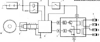
Contact ignition circuit installed in the first VAZ 2107 models
Note. The first 2 varieties were installed on the “seven” with a carburetor, the latter was introduced together with an injector.
In the mechanical version, the contacts opened by the cam of the distributor shaft break the low voltage circuit, initiating the formation of a powerful pulse in the secondary winding of the coil. This discharge is directed to the electrodes of the spark plug, which ignites the fuel in the cylinder where the piston has risen to top dead center (TDC) and the compression stroke is completed.
Scheme of non-contact ignition of the seven with a carburetor
The contactless circuit operates on the same principle, only the signal to break the circuit is supplied by the Hall sensor, and it is implemented by the switch. Therefore, setting the ignition on carburetor “sevens” is done almost identically. Another thing is cars with an injector, where a new system has been introduced that does not have not only contacts, but also a distributor and any moving parts. Here, the moment of spark formation is determined by the ECU controller, which is guided by the signals of various sensors.
Connection diagram for high voltage wires
Connecting new or removed old wires must be done strictly according to a specific scheme. Otherwise, the spark will not coincide with the compression stroke in the cylinder block.
In other words, when the fuel mixture is ready to ignite in the cylinder, a spark is required to ignite it. If the connection is incorrect, the spark will not appear at the required moment and ignition will not occur, which will make starting the engine impossible.
Scheme
The order and counting of cylinders in VAZ engines starts from the timing belt drive, from left to right, that is, the first cylinder will be at the timing belt, and the 4th at the oil filler neck.
Most often, the cylinder number is indicated on the ignition module, but there are cases when there are no designations on the module, then it is necessary to connect the cylinders according to the diagram shown below.
- The first cylinder is connected to the lower left contact on the MH;
- The second cylinder is connected to the upper left contact on the MH;
- The third cylinder is connected to the upper right contact on the MH;
- The fourth cylinder is connected to the lower right contact on the MH;
Ignition adjustment
The injection modification of the VAZ 2107 does not require adjustment of the ignition timing. The electronic control unit, using a sensor, determines the optimal ignition timing. The participation of the car owner in adjusting the operation is limited to setting the engine timing belt to the marks.
To check the performance of the ECU and the functionality of the sensors, it is necessary to connect a computer with specialized software. In this way, the cause of most electronic ignition system malfunctions can be determined.
It is also worth checking the operation of the throttle position sensor yourself. When the throttle is closed, the voltage on the sensor should be no higher than 0.55 volts, and when fully open - 4.5 volts. Measurements must be made with a voltmeter with the ignition on.
The ignition module is one of those mechanisms in which it is quite difficult to determine the presence of malfunctions. They pay attention to it when serious deviations in the operation of the car are observed. If the VAZ 2107 engine does not start immediately, it is recommended to adjust the ignition, and if the engine is running unevenly, a proper check is required. The main thing here is not to forget that the ignition module of an injection engine is a system that, using coils, generates electrical energy to generate a spark and further start the vehicle.
Cost and articles
Below are prices and articles for good and high-quality high-voltage wires for VAZ cars, both for 16 and 8 valve engines.
| Manufacturer | Number of valves | vendor code | Price, (rubles) |
| Standard | 16 | 21120-3707080-81 | 990 |
| SLON | 16 | 2112-3707080 | 1450 |
| VOLTON | 16 | VLT-2112005 | 915 |
| TESLA | 16 | Т516M | 1710 |
| LADA | 8 | 21110-3707080-82 | 695 |
| TESLA | 8 | Т514M | 875 |
| Standard | 8 | T684H | 620 |
| Original | 8 | 21110-3707080-12 | 710 |
Preparatory stage
To set the ignition on a VAZ 2107 car, no special conditions are required; the operation can be done both in the garage and on the street, including in winter. For work, prepare the following set of tools:
- flat screwdriver;
- metal probe 0.35 mm thick;
- open-end wrench size 13 mm;
- a car light bulb designed for a voltage of 12 V with wires soldered to it;
- a wrench with a long handle designed to turn the crankshaft;
- key for unscrewing spark plugs.
Ignition tuning tool
Note. Instead of a special key to rotate the crankshaft, you can use a regular open-end wrench measuring 36 mm. If you don’t have such a key, then you will have to set the marks in the old proven way: by engaging 4th gear and raising the rear wheel, turn it manually, thereby turning the crankshaft.

