03/02/2022 1,922 Electrical
Author: Victor
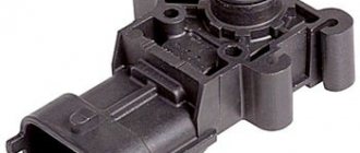
If the mass air flow sensor fails, the operation of the injection system will be disrupted, and therefore the functioning of the car’s engine as a whole. If signs of a malfunction of the mass air flow sensor appear, the easiest diagnostic method is to install a known working device instead of the controller.
[Hide]
What is a mass air flow sensor and its purpose
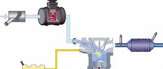
In a car, this controller is a device used to estimate the volume of air that enters the engine. The sensor belongs to the class of regulators of the electronic control mechanism of the power unit. The first thing that the mass air flow sensor affects is the operation of the injection system. The device is designed to determine and regulate the air flow that enters the engine cylinders in order to form a combustible mixture. The controller in a car can be used in conjunction with air pressure and temperature sensors, which are used to change its readings.
What mass air flow sensors are installed on VAZ
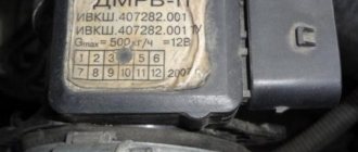
Three types of sensors were installed on VAZ cars with fuel injection systems and HFM5 type air flow sensors from BOSCH, which do not differ in appearance in any way, but are distinguished only by numbers (articles). The first to be installed were sensors ending in 004 - there were few such sensors, so you rarely see them. And the next two: 116th and 037th sensors were installed on most VAZ models.
They differ in that the 116th mass air flow sensor has a smaller error and other operating parameters. Therefore, these mass air flow sensors are not interchangeable, although they are similar in appearance.
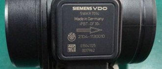
There were also Siemens mass air flow sensors, but this article is not about them.
MAF 037 was installed on VAZ 2111, 2112, 2123, 21214, with ECU M 1.5.4, January 5.1-5.1.3, etc.
DMRV 116th on VAZ 21114, 21124, 21214, as well as Kalina and Priora with ECU M 7.9.7 and January 7.2
Principle of operation
The principle of operation of the mass air flow sensor can be based on counting Kraman vortices or shifting the potentiometer slider by means of a blade mounted on the air supply flow.
The first option is considered more reliable, since it is not equipped with moving structural elements. In this case, the device counts Kraman vortices appearing in laminar air flow. On the way of the latter, special obstacles with sharp edges are used as resistance. An air flow breaks off from them, which linearly depends on its speed. This type of controller only works if there is turbulence in the air.
If the air speed is too high, it can lead to the formation of parasitic pressure pulsations. Therefore, the design of the devices is often supplemented with an input for changing the sensitivity of the measuring component. This may be required at low air flow rates when the power unit is idling. Vortex-type mass air flow sensors on older cars used two ultrasonic elements - a transmitter and a receiver. Then they began to use devices in which the function of measuring pulsations to count vortices is performed by a heating filament.
The StarsAuto channel talked about the design features, as well as the operating principle of automobile flow meters.
If the sensor is equipped with a measuring potentiometer, it operates on the principle of slider displacement. Its working blade is equipped with a spring and is installed in the flow of consumed air by the motor. If it increases, a proportional displacement of the blade occurs. The flow has a pulsating nature; accordingly, to reduce the effect of pulsations, the controller blade is connected to a damper. A potentiometer slider is also associated with it, which, when the sensor operates, moves to a level proportional to the volume of air flow.
This structural element is made on a ceramic surface where the resistor elements of the voltage divider are installed. Their leads are arranged in a row and covered with a special resistive layer. The device slider is pressed against the contact component. Due to this, the voltage level on it corresponds to the value at the point of contact with the resistive layer. If the blade changes its position, the elements move, which leads to abrasion of the slider.
Design of the mass air flow sensor
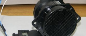
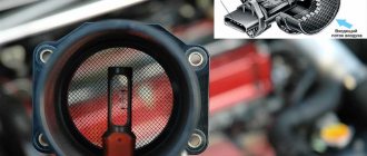
Structurally, the mass air flow sensor includes six elements:
- working board of the device;
- plastic case;
- radiator element;
- sensitive component in the form of a wire or nickel network;
- the pipe through which the air flow passes;
- meshes at the outlet and inlet of the device.
Current must be supplied to the sensitive component, otherwise it will not be able to heat up. When the device is operating, the average filament temperature should be 75-100 degrees.
Photo gallery “Design of mass air flow sensor”
Filament device with circuit board inside
Film flow meter for cars
Where to buy car accessories
Spare parts and other products for the car are easily available for purchase at auto stores in your city. But there is another option that has recently received significant improvements. You no longer need to wait a long time for a parcel from China: the AliExpress online store now offers the opportunity to ship from transshipment warehouses located in various countries. For example, when ordering, you can specify the “Delivery from the Russian Federation” option.
Follow the links and choose:
| DVR, Dual, 1080P, 4G, Android 8.1, 10-inch | Charger with two USB ports, 5 V | AUTOOL X95 car compass, horizontal inclinometer, speedometer |
| 12V car heater | HD night vision camera with 360 degree viewing angle | Karadar G820STR radar detector with GPS |
The most popular DMRV malfunctions
The main signs of a malfunction of the mass air flow sensor:
- Problems with the flow meter can be reported by the Check Engine indicator, which appears on the dashboard inside the car.
- Depending on the type of device and machine, an icon may appear on the control panel indicating a low level of the air flow sensor signal.
- The power unit began to work intermittently. When the sensor is disconnected, the car stalls or the engine speed begins to jump up or down. The power of the internal combustion engine decreases, the car has difficulty accelerating, especially when moving uphill.
- Increased fuel consumption.
- When changing gears on the gearbox, the engine randomly stops.
A faulty sensor can be determined by the integrity of the housing. The presence of damage on it, as well as on the corrugated line, may indicate problems with the controller. We are talking about the pipe that connects the regulator to the throttle valve. If the engine randomly stalls during operation, this may indicate a malfunction in the power line.
If the air quantity and distribution control device is faulty, then the symptoms of the breakdown may be similar to errors in the operation of the air filter.
Reasons why the device fails:
- the sensor is not connected to the machine's power supply;
- break or damage to the power supply circuit;
- malfunctions in the operation of the controller can be caused by malfunctions in the functioning of the engine control unit;
- incorrect connection of signal cables or their breakage;
- oxidation or damage to contact elements.
Symptoms of a problem
Considering the symptoms that indicate a malfunction of this sensor, one cannot help but mention the following:
- The CHECK ENGINE controller is triggered;
- At idle, uneven engine operation is noted;
- There are problems with acceleration dynamics;
- The engine runs at very high or too low speeds;
- Increased fuel consumption is observed;
- The engine does not start at all.
In addition, there are other reasons for the inoperability of this unit, in the presence of which checking the mass air flow sensor is not only desirable, but necessary. Most often, we are talking about cracks that form in the corrugated hose connecting the throttle module to the flow meter, problems with the power supply, or damage to the wiring of the sensor.
Diagnostics of mass air flow sensor
If there is no similar sensor, then there are other ways to check the performance of the flow meter:
- visual diagnostics;
- checking while driving;
- determining firmware compliance;
- diagnostics with a tester.
Visual inspection
Before checking the device using this method, it must be removed from its mounting location. To do this, the pipes are disconnected from the housing of the air filter element. The inside of the controller must be dry; traces of motor fluid and condensation are not allowed. Often the device breaks down due to non-compliance with the air filter replacement intervals, as a result of which dirt remains on the sensitive component. This leads to the controller giving incorrect readings.
If there are traces of motor fluid on the internal cavity of the controller, this indicates a high level of lubricant pressure in the power unit. The reason may be a clogged crankcase ventilation. When checking, you need to make sure that the sealing element is located in the right place where the corrugation is installed. This part may have become stuck in the air filter housing. With this problem, air leaks into the engine, which gets inside with dust and contaminates the regulator.
Diagnostics on the move
It is necessary to disconnect the plug with the power circuit from the sensor and start the engine, and then disconnect the block. The Check Engine indicator will appear on the dashboard. The minimum engine speed should increase to 1500 per minute. If the engine begins to operate more stably after turning off the device, this indicates a malfunction. The sensor needs to be replaced.
User Igor Belov spoke about several methods for diagnosing the flow meter, including checking while driving.
Compliance of the mass flow sensor with the ECU firmware
To check the firmware compliance, you need to take a 1 mm thick plate and place it under the damper stop, this will lead to a change in engine speed. Then the block with wires is disconnected from the controller. If the car engine does not stop, then the reason is the firmware of the microprocessor module, idle speed controller without a flow meter in emergency mode.
Checking the mass air flow sensor with a multimeter
For diagnostics, the ignition is activated, but the power unit does not need to be started. Use the contact of the red probe on the tester to touch the first cable (yellow), and the black one goes to ground (green contact). It is not recommended to use sharp objects for connection, as this will lead to errors in the readings. This diagnostic method will allow you to determine the voltage level between the conductors.
The status of the sensor will be determined by the following readings:
- from 0.99 to 1.01 V - parameters of the new controller;
- 1.01 - 1.02 V - the regulator is in excellent condition, no need to change;
- 1.02 - 1.03 V - generally satisfactory condition of the device;
- 1.03 - 1.04 V - the controller’s service life is almost exhausted, replacement will soon be required;
- 1.04 - 1.05 V - the sensor is in unsatisfactory condition, it’s time to change the device.
Diagnostics by the tester may not be performed on all types of flow meters. The pre-diagnostic mode of the multimeter must be configured to measure the value of direct current and set the maximum parameter to 2 V. Four cables are connected to the controller, each of which is designated by a specific color.
Starting from the near conductor to the windshield:
- the yellow contact is intended for input of a flow meter pulse;
- a white or gray cable is used as the supply voltage output channel;
- green contact is ground or ground;
- The black cable, equipped with a pink stripe, is responsible for the output to the main relay.
The colors of the contacts on the mass air flow sensor may be different, but the arrangement of the wires is always identical.
The “Simple Opinion” channel talked about performing diagnostics on a flow meter using a tester.
Installation location
To save fuel, modern cars are equipped with injection engines with electronic ignition. In a simplified form, an injector is a point injection of a mixture through a nozzle into a cylinder or intake tract. The ECU control unit is usually called the “brains” of the car; it is this body that adjusts the four main parameters of the electronic control system (ECM):
- injection frequency;
- injection moment;
- fuel mixture dose;
- the ratio of fuel and air in it.
To obtain this data, the principle of remote sensors is used. For example, the moment of injection is determined by the readings of the crankshaft sensor DPKV, and the mass air flow sensor is responsible for the proportions of the mixture. All air entering the car engine passes through the throttle valve, which is located between the intake manifold and the air filter.
Rice. 3 VU meter location
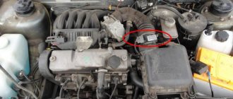
Therefore, it is most logical to look for the mass air flow sensor directly in front of the throttle valve, where it is located
Attention: Information is transmitted to the controller from seven sensors: camshaft DRV, detonation DD, lambda probe, throttle valve DPZ, cooling system DTOZh, volume meter DPKV and crankshaft DPKV. Based on these signals, the ignition module is turned off, the fuel pump and injectors, the fan and the idle regulator are turned on.
What to do if the MAF signal level is low?
When this problem occurs, diagnostics is performed:
- the presence or absence of supply voltage, as well as the reliability of connecting the device to ground;
- resistance level between contact element 5 (in the diagram) of the connector and ground, this indicator should be from 4 to 6 kOhm.
The problem may be:
- poor quality contact;
- incorrect wiring harness route;
- wear or damage to the cable core or insulating layer;
- poor connection of the device to ground;
- connecting more powerful energy consumers to the block.
Device diagnostics includes the following steps:
- The quality of contact between pins 7 and 12 on the injection system connector, as well as the sensor, is checked. A visual check of the condition of the block is performed to ensure correct connection. The problem may be damage to the locks or the use of damaged contact elements. The connection quality of the conductor to the block may be poor.
- You need to make sure that the harness route is not broken. Problems may arise if the cable harness is laid close to high-voltage wires.
- The integrity of the harness is checked to ensure that it is not damaged. If the element is visually intact, you need to try to move it and at the same time monitor the readings of the diagnostic equipment.
- The air filter device is also checked for clogging. If required, it is replaced.
If you have a tester, you can check the serviceability of the mass air flow sensor as follows:
- The key is turned in the lock to turn off the ignition. It is necessary to disconnect the connector with wires from the controller.
- Then the ignition is turned on, but the power unit does not start.
- The tester is used to diagnose the voltage level between the contact elements on the connector. Between outputs 2 and 3 this value should be above 10 volts, between 3 and 4 - 5 V, and between ground and the third contact - 0 V. If the values obtained are different, it is necessary to eliminate breaks in the line and get rid of the short to ground.
- Then the ignition in the car is turned off. Using a multimeter, you can diagnose the resistance level between the fifth contact and the ground on the block.
Connection diagram of the flow meter to the microprocessor
If the resulting value is about 4.6 kOhm, then the regulator itself is faulty. The problem may lie in its poor-quality connection. If the resistance level is 0 ohms, the problem is a short to ground of the fourth contact or a malfunction of the sensor. If the obtained value is more than 100 kOhm, this indicates a break in the 4G wire or a breakdown of the regulator.
Reasons for failure
The main causes of failure of a frequency or electronic flow meter:
- The mesh located inside the device is clogged. Crankcase gases or propane pass through the regulator along with the air flow when it is connected to the throttle assembly module. This leads to the formation of deposits on the sensor threads, which disrupts normal operation and increases fuel consumption.
- Failure of threads as a result of natural wear or improper use. The mass flow sensor has a limited service life, which on average is about 100-150 thousand kilometers. Failure of the regulator is also possible as a result of detonation of the controller in the throttle assembly.
- Power unit overload. As a result of overheating of the flow meter and its individual components, incorrect data may be sent to the motor control unit. When the metal is seriously heated, the level of its electrical resistance changes, which leads to a change in the calculated data for the volume of air passing through.
- Mechanical damage to the sensor, which could occur when replacing the air filter or other mechanisms and components located in proximity to the regulator. It is possible that the contact elements located on the connection block may be damaged during installation.
- Large volumes of water entering the engine compartment. This leads to a short circuit on the power supply and control lines of the flow meter.
What to do if the MAF signal level is high?
In case of this problem, you also need to check the presence of voltage on the power circuit and the quality of the connection of the sensor to ground. The parameter is also diagnosed on the fifth pin of the connector.
The check is done like this:
- The ignition is turned off. You need to disconnect the connector with wires from the device.
- The ignition turns on, the engine does not start.
- Using a multimeter, you can diagnose the voltage on the block. The readings obtained should be the same as when the sensor signal is low.
- Then the resistance is measured; the tester must first be configured in the appropriate mode. The measurement is made between the fifth contact element and ground. If the resulting value is 0 V, then the regulator is faulty and must be replaced. Other parameters will indicate a short circuit of the 4G conductor to the power source.
In what situations is it necessary to check the control device?
The following signs indicate that the controller has failed:
- Check is on, errors appear during system self-test;
- fuel consumption increased;
- the car began to slowly pick up speed;
- problems with hot starting of the engine;
- reduction in engine power.
Most often, the breakdown of the mass air flow sensor occurs after mechanical damage to the sensor or due to the negligence of the owner of the VAZ-2110. In particular, you need to check the condition of the rubber seal. If it is worn out, air mixed with foreign particles will enter the sensor. As a result, the wire will become dirty and the readings of the device will be distorted. The easiest way to test this device is to use a multimeter.
How to clean the sensor yourself?
By cleaning and flushing the air flow controller, you can restore its operation.
In particular, you will have to work with the sensitive element of the sensor - this part always becomes dirty during operation of the flow meter.
Selecting a cleaner
To complete the task you need to purchase a cleaning agent:
- Liquid Moly. This brand's mass air flow sensor cleaner is not cheap. But its use allows you to effectively remove contaminants and restore the operation of the device. The use of Liqui Moly cleaning products can be carried out on mass air flow sensors running on gasoline or diesel internal combustion engines.
- Technical or medical alcohol. This option is one of the oldest and most effective. The chemical properties of alcohol allow you to efficiently remove dirt from the sensitive part of the sensor.
- Carburetor engine cleaner. One of the most inexpensive and effective ways to restore the controller.
- Liquid key product. Allowed for use not only on mass air flow sensors, but also for cleaning other components and mechanisms.
- WD-40. Allows you to remove not only dirt, but also traces of rust.
Step-by-step instruction
Do-it-yourself repair of the mass air flow sensor is carried out as follows:
- Before removing the sensor, turn off the ignition and disconnect the terminal from the battery. In the engine compartment, the connector is removed from the flow meter.
- A pipe is connected to the device; it is also loosened and disconnected. Using a wrench, you unscrew the bolt that secures the mechanism to the air filter, in particular, to its body.
- The device is removed from the corrugation. Depending on the car model, this may require different tools, including star keys. The screws securing the device are unscrewed, and then the flow meter is removed from the landing site.
- If there are traces of oil on the device, they must be removed. To clean, use one of the products described above.
- The sensors themselves on the flow meter are usually made in the form of a wire located on a mesh. When using a cleaner, you must carefully treat the sensitive component. The film must not be damaged. When the area of contamination is cleaned, you need to wait about 10 minutes for the product to take effect.
- If there is too much dirt on the device, then it is advisable to repeat the cleaning procedure several times. To ensure rapid evaporation of the product, you can use a compressor or pump. But too high a pressure can destroy the sensing element of the flow meter.
Photo gallery
Dismantling the flow meter
Cleaning with WD-40
Cleaning the air flow meter
Since the manufacturers do not provide for repair of the mass air flow sensor, this electrical device is considered “consumable”. There is no consensus on the possibility of cleaning to restore performance, even among service station professionals. If the car owner nevertheless decides to clean the mass air flow sensor on his own, it is necessary to take into account the nuances of the technology:
- the cleaner should not contain acetone or ether;
- Cotton swabs and compressed air are prohibited;
- most often WD-40 or Air Senso Clean from CRC is used;
- After removing the device, the spray is applied to it evenly with a powerful jet, the dirt dissolves and flows off under its own weight.
Rice. 14 Cleaning the VU meter with spray
Installation of the mass air flow sensor in place is possible after drying the surfaces without using a hair dryer.
Do-it-yourself replacement of the mass air flow sensor
If repairing the device does not help, then it will have to be replaced; you can perform this task yourself.
Step-by-step instruction
Replacing the mass air flow sensor is done as follows:
- The ignition is turned off and the engine compartment of the car is opened.
- The negative terminal is disconnected from the car battery; this is necessary in order to cut off the power supply.
- Using a screwdriver, loosen the clamp that secures the corrugation to the sensor.
- The pipe is removed.
- The power supply is disconnected from the flow meter.
- Using a wrench, unscrew the bolts securing the device to the filter element housing.
- The controller is removed and then replaced. All elements are subsequently assembled in reverse order.
Removing the sensor and replacing it
MAF sensor location
Locate the MAF between the air filter box and the throttle body. On some models, the sensor is located inside the air filter housing.
If you need help finding a meter, get a vehicle repair manual for your specific make and model of car.
| Index |
| 1. Quick MAF Diagnostic Procedure Without DMM |
| 2. How to check |
| Power check |
| Voltage Signal Testing |
| Frequency Signal Testing |
| Hot Wire Testing |
| 3. I replaced the faulty MAF sensor, but I see no improvement |
| 4. What if my sensor is faulty? |
Locate the MAF sensor in the air filter assembly.
Recommendations for extending the service life of the mass air flow sensor
The service life of the device is affected by the purity of the air flow that passes through it. Therefore, when using a flowmeter, it is necessary to prevent the formation of deposits on its working surface. To do this, it is recommended to periodically check the functioning of the air filter device. If necessary, the sensor must be changed regularly. If the car is operated in a large and polluted city, then the part must be replaced more often than indicated in the car maintenance regulations.
Video “Diagnostics and malfunctions of mass air flow sensor”
The 24 Hours channel spoke in detail about the signs of malfunction of flow meters and how to diagnose them yourself.
Do you have any questions? Specialists and readers of the AUTODVIG website will help you ask a question
Was this article helpful?
Thank you for your opinion!
The article was useful. Please share the information with your friends.
Yes (100.00%)
No
X
Please write what is wrong and leave recommendations on the article
Cancel reply
Rate this article: ( 2 votes, average: 5.00 out of 5)
Discuss the article:
