Retarder brake
,
retarder
(English retarder), is a device designed to reduce the speed of a vehicle without using the main braking system. The use of a retarder is necessary for the operation of vehicles (mainly trucks and buses, as well as trains) in mountainous conditions on long descents. Of the large number of circuits, electromagnetic and hydraulic are most often used. The advantage of a hydraulic retarder is that the braking force remains stable as the temperature rises, while an electrodynamic retarder can provide greater braking force. In addition, there are retarder brakes that are capable of recovering energy during braking and then returning it during acceleration.
At the installation site, there are primary retarders - installed on the input shaft of the gearbox or on the engine shaft, and secondary - on the secondary shaft of the gearbox.
Intarder is a transmission brake-retarder for buses and medium-duty trucks of the European design school; development of the German company ZF Friedrichshafen AG. By design it is a retarder (retarder), built-in (integrated - in
) into the gearbox. If the retarder is combined with the gearbox, it is called integrated: ZF even introduced a separate name for it - “intarder”. It is connected to the output shaft not directly, but through a pair of gears with a gear ratio of approximately 1:2, so the rotor speed is twice as high (which improves braking torque characteristics at low speeds).
An engine brake is also classified as a retarder; there are several types of it. The oldest design is a compression brake, used, in particular, on some modifications of YaMZ-236 and 238 engines for MAZ, Ural, KrAZ trucks - a flap in the exhaust manifold that blocks the exhaust gas outlet, which creates back pressure that brakes the engine and the vehicle. This also cuts off the fuel supply to the cylinders. Both actions are performed by pneumatic cylinders, activated by a pedal located under the clutch pedal. [1]
The American inventor Jacobs created another type of engine brake - a decompression brake, named after him Jake brake and in one form or another adopted by manufacturers in other countries. The essence of the Jake brake is to release air from the cylinder immediately after the compression stroke, so the air is not used to burn fuel, the engine does not produce useful work, but acts as a compressor. For example, on the Detroit Diesel MBE 4000 engine (Mercedes-Benz OM 460 LA), found on some Freightliner and other trucks, each cylinder has a special small exhaust valve opened by a pneumatic actuator for braking. [2] In Iveco Cursor engines, the decompression brake is implemented differently - the exhaust valve rockers (rocker arms) sit on an eccentric shaft, and the camshaft has two cams for each exhaust valve - high and low. During normal engine operation, the valves are controlled only by the high camshaft cams, and the low cams do not operate due to clearances; when the eccentric shaft is turned, the rockers are lowered and the low cams open the exhaust valves after the compression stroke. [3]
Mountain brake: operating principle
The mountain brake is the simplest, cheapest and most versatile means of braking a car.
A mountain brake is an additional braking system. It ensures the vehicle moves at low speed. Installed on trucks, road trains and buses.
The essence of the operation of the exhaust brake is to turn off the fuel supply and partially block the exhaust tract in order to create back pressure during the exhaust stroke.
Most often it is a damper with a vacuum servo drive.
The valve is designed in such a way as to ensure that the residual clearance is sufficient to ensure that too much back pressure does not interfere with the normal operation of the exhaust valve.
The exhaust brake allows the working brake system to rest, remaining in a cold state, so that in a critical situation it does not fail and stop the car.
Muffler Kamaz 65115 Cummins Euro-4
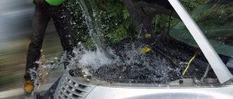
The Kamaz-65115 is equipped with a muffler from Cummins that operates according to the Euro-4 standard. This muffler weighs quite a lot, approximately 21 kg. Its height is 35 centimeters and its length is 1 meter. It is an active-reactive device. The muffler is not soundproofed, so it is quite noisy. As mentioned earlier, the muffler meets all Euro-4 standards. It is made of radiocarbon steel, which is specially treated with an anti-corrosion agent for the metal. This ensures a long and safe service life of the spare part in the absence of mechanical damage.
On the Internet you can find a video on assembling and disassembling the Kamaz 65115 Cummins Euro-4 muffler.
Types of mountain brakes
There are three types of auxiliary brakes: motor, hydraulic and electric. At idle, the engine itself can operate as a retarder. But its braking torque is only enough for a passenger car.
The engine brake is a special device that turns off the fuel supply. It is installed in the car engine.
During braking, the damper closes the muffler pipe and moves the fuel pump rack. Gasoline is not supplied. The engine stalls, but the crankshaft continues to rotate.
The piston tries to push air out of the cylinders. He experiences strong resistance. Because of this, the rotation of the shaft and, accordingly, the drive wheels slows down.
Hydraulic
The hydraulic retarder consists of two wheels with blades. They are located in parallel. The distance between the wheels is small. There is no hard connection.
One wheel is fixed to the cardan shaft and rotates with it. The second is on the brake housing. It is motionless.
The hydraulic brake housing is filled with oil through a special pump. It is accelerated by the blades of a rotating wheel. Flows over to a stationary one and loses speed.
Once again falling on the first wheel, the oil slows down its rotation. The braking torque is transmitted to the driving wheels of the car.
Electric
In an electric braking system, a rotor is connected to a shaft. And the stator windings are placed in the housing.
When voltage is applied to them, an electromagnetic field appears. It does not allow the rotor to rotate at the same speed.
When you need to slow down, the entire space is immediately filled with oil.
Being a thick liquid, oil creates a lot of resistance to the rotation of this propeller.
The blades on the body also contribute to this. It is difficult for the propeller to rotate in such a dense environment, so it will also slow down the drive wheels through the driveshaft.
Where does the kinetic energy taken during the braking process go? And it is used to heat that same oil, so this heat is transferred to the standard radiator through a heat exchanger, or to its own oil radiator.
In general, this design is very similar to the torque converter of an automatic transmission.
Only if there the property of oil viscosity was used to transmit torque to the drive wheels from the engine, here this property is used vice versa, to remove torque from the drive wheels and convert it into heat.
Source
How does the pneumatic drive of brake systems work?
Operation of the service brake system drive
Compressed air from the compressor flows through the pressure regulator and antifreeze guard to the safety valve block. It consists of double and triple valves that fill the receivers of all circuits of the brake systems with air.
The safety valves are adjusted so that first the receivers of circuit III (parking and spare brakes) are filled, and then the receivers of the remaining circuits.
Air from receivers with a capacity of 40 and 20 liters enters the corresponding sections of the brake valve. When you press the brake pedal, air from the lower section through the pressure limiting valve enters the brake chambers (type 24), which operate the brake mechanisms of the front axle wheels. From the upper section of the valve, air is supplied through the brake force regulator to the brake chambers (type 20), which activate the brake mechanisms of the wheels of the middle and rear axles. At the same time, air is supplied from both service brake circuits through separate lines to the trailer brake control valve with a two-wire drive.
Operation of the spare brake system drive
The parking brake valve has a tracking device that allows you to slow down the car with an intensity depending on the position of the brake valve handle.
When the tap is turned, air is released from the control line of the accelerator valve, the amount of which is proportional to the angle of rotation of the handle. In this case, through the atmospheric outlet of the accelerator valve, a corresponding amount of air leaves the cylinders of the spring energy accumulators. Simultaneously with the braking of the car, the trailer or semi-trailer is braked.
Operation of the parking brake system drive
To brake a car or road train on a riser, it is necessary to install the brake valve handle in the rear fixed position. At the same time, air from the control line of the accelerator valve escapes into the atmosphere. At the same time, air is released from the cylinders of the energy accumulators of the brake chambers through the atmospheric outlet of the accelerator valve. The springs, unclamping, activate the brake mechanisms of the rear and middle axles. At the same time, the brake valve turns on the trailer brake control valve with a two-wire drive.
To release the parking brake, the brake valve handle should be set to the front fixed position. In this case, the air from the receivers passes through the brake valve and enters the control line of the accelerator valve, which is activated and begins to pass compressed air from the receiver through the bypass valve, bypassing the brake valve, into the spring energy accumulators. At the same time, the power springs are compressed and the trailer is released.
In the event of an emergency drop in pressure in the parking brake drive circuit, the spring energy accumulators are activated and the vehicle is braked. In order to release the brakes, you must use the emergency brake release system.
When you press the emergency brake release valve, compressed air from the air receivers through a three-line safety valve and a bypass valve will enter the cylinders of the spring energy accumulators and compress the springs, releasing the car.
If there is no supply of compressed air in the emergency brake release circuit, the vehicle can be released using devices for mechanical brake release, which are built into the cylinders of spring energy accumulators. To do this, turn the screw all the way. At the same time, it will rest against the bottom of the piston through the thrust bearing and lift it up, compressing the power spring of the energy accumulator. The pusher, rising, will release the brake chamber rod, which will rise upward under the action of the return spring. The springs will tighten the pads and the car will release the brakes.
Operation of the auxiliary brake system drive
When you press the auxiliary brake valve, compressed air from the receiver enters the pneumatic cylinders. The cylinder rod connected to the fuel pump rack lever will move and the fuel supply will stop. The cylinder rods connected to the auxiliary brake flap levers will turn the flaps, and they will block the exhaust pipes of the muffler.
The contacts of the pneumoelectric sensor installed in the line in front of the cylinder will close, and the trailer's solenoid valve will turn on, which will partially allow compressed air from the trailer's air cylinder into its brake chambers. Thus, the trailer is slowed down, which prevents the road train from “folding.”
Installing a mountain brake on a Kamaz
Auxiliary braking system
, which limits the speed of the vehicle on long descents, is carried out independently of other braking systems. When driving downhill, the vehicle begins to gradually accelerate, reaching a speed that is dangerous from the driver’s point of view for safe movement. The driver slows down using the service brake system, reducing the speed to a safe one. After some time, the car accelerates again and the braking cycle repeats. During a 5–20 km long route from a pass, the braking cycles of the working system are repeated many times. This is accompanied by wear of tires, brake linings and, most importantly, an increase in the temperature of the brake mechanisms, primarily the brake linings. When the brake linings heat up, the coefficient of friction of the lining on the brake drum decreases, and, consequently, the braking efficiency of the brake mechanism. As a result, the braking efficiency of a car at the beginning of a descent from a mountain and at the end, all other things being equal, is completely different. A sharp deterioration in the braking properties of a car with hot brake mechanisms can lead to a traffic accident with serious consequences. Therefore, a braking system was developed for heavy vehicles and road trains that ensures long-term movement on a descent at a low constant speed without using (and warming up) the mechanisms of the service brake system. The latter must remain cool and ready to brake at any time with maximum efficiency. Such a system is an auxiliary (second name is wear-resistant) braking system. The assistance system cannot reduce the vehicle speed to zero. According to regulatory documents, the effectiveness of the auxiliary braking system is considered sufficient if, on a 7% slope of 7 km in length, the vehicle speed is maintained at (30±5) km/h. Structurally, the auxiliary braking system is now implemented in three ways: engine brake, hydraulic retarder
and
an electric retarder
. It should be borne in mind that the engine running at idle speed can be used as a retarder on every vehicle (so-called engine braking). The braking torque created in this case by the engine increases when lower gears are engaged in the box. However, the braking torque developed by the engine running at idle speed is small and does not provide the necessary deceleration of a large vehicle. A more efficient engine brake (mountain brake) is a car engine equipped with additional devices for turning off the fuel supply and turning the flaps in the exhaust pipe, which create additional resistance. When braking, the driver, using a pneumatic drive, turns the damper in the muffler pipe to the closed position and moves the high-pressure fuel pump rack to the position of zero fuel supply to the engine. As a result of these actions, the car engine turns off (but the rotation of the crankshaft does not stop) and it becomes impossible to release air from the cylinders through the exhaust tract. During the exhaust stroke, the piston tends to push air through the exhaust manifold. In this case, the piston experiences resistance, repeatedly compressing the air. The consequence of this resistance to the movement of the piston is a slowdown in the rotation of the crankshaft, and, consequently, the transmission of braking torque from it through the transmission to the driving wheels of the car.
: 1— body; 2 - impeller
The hydraulic retarder is a device of two bladed wheels, not rigidly connected to each other, but located opposite each other at a short distance. The impellers are installed in a separate housing or built into a hydromechanical transmission (HMT). One impeller is mounted on a transmission shaft, such as a driveshaft, and rotates with it, while the second impeller is stationary and connected to the brake housing. To create resistance to rotation of the propeller shaft, the housing is filled with oil using a special pump. The oil is accelerated by the blades of the rotating wheel, flows to the blades of the stationary wheel, where its speed sharply slows down and then re-enters the blades of the rotating wheel. When oil gets on the blades of a rapidly rotating impeller, the rotation of the latter slows down, and the resulting braking torque is supplied through the transmission to the drive wheels of the car. The oil heated in the retarder housing is cooled in a special radiator. To release the brake, oil is removed from the housing. The hydraulic retarder can provide several levels of braking intensity if installed in front of the gearbox. The lower the gear, the more effective the braking.
Car device
Retarders of various designs and operating principles can be used as an auxiliary braking system for a vehicle. A retarder is a device designed to reduce the speed of a vehicle without using the service braking system.
The use of retarder brakes helps prevent overloading of the working brake system and its overheating due to prolonged intensive work when driving on a long descent. In such a situation, the driver has to constantly slow down, since the car tends to accelerate downhill, and must be held with the brakes. Prolonged load on the friction brake system leads to its overheating and premature wear. In practice, during long descents, drivers have to periodically stop the car and wait until the brakes cool down. And if the car is often driven in mountainous areas, then the cost of repair and maintenance of brakes increases sharply. For these reasons, retarders are used as an auxiliary braking system.
The word "retarder" translated into English means "retarder", which is why retarder brakes are sometimes called retarders. However, the term “retarder” is more often applied to special devices that are installed on the drive shafts of the engine or transmission in order to slow down the vehicle when necessary. Retarder brakes, which use the braking properties of the engine in compressor mode, are more often called simply an auxiliary brake, or a mountain brake.
Hydraulic, electric, compressor and aerodynamic brake mechanisms are usually used as retarder brakes on vehicles. Aerodynamic retarders are sometimes used on high-speed and racing cars. They are made in the form of special shields, flaps and parachutes, which increase the force of air resistance, and are used for emergency braking of cars moving at high speed. The use of conventional braking systems on such vehicles is not always effective and safe.
In addition, there are retarder brakes that are capable of recovering (accumulating) energy during braking and then returning it during acceleration. These, for example, include inertial retarders with massive flywheels. When a car brakes, the energy of its movement is transferred through special devices to the flywheel, which spins up. In the future, the energy of the rotating flywheel can be used to accelerate the car without significant fuel consumption.
The simplest example of using a retarder is engine braking - in this case, the fuel supply to the cylinders is stopped (or reduced), switching the engine to compressor mode. As a result, the engine begins to resist the movement, slowing down the car. If the retarder is integrated with the gearbox, it is usually called an “intarder”, i.e. integrated into the gearbox.
Hydraulic retarder
The hydraulic (hydrodynamic) brake retarder is structurally a fluid coupling, one of the wheels of which is fixedly fixed, and the other is mounted on the transmission shaft (behind the gearbox) and rotates with the shaft. When the retarder is turned on, its body and the space between the wheel blades are filled with liquid. The centrifugal force that arises when the rotor rotates tends to displace fluid to the outer part of the housing, while the stator impeller prevents this by changing the direction of fluid flow in such a way that, acting on the rotor blades, it has a retarding effect and slows it down. In the off state, when there is no liquid in the moderator housing, the blades rotate freely and practically do not interact. The braking torque of a hydraulic retarder depends on the speed of rotation of the impeller and the amount of fluid supplied.
Hydraulic retarder brakes have a large mass and are ineffective at low vehicle speeds.
When a hydraulic retarder operates, the oil can become very hot, so special devices are used to cool it. One type of hydraulic retarder, called an aquatarder, is installed at the front of the engine and uses fluid from the engine cooling system as its working fluid. Such a retarder, the operating principle of which is no different from any other hydrodynamic device, does not require forced cooling, which significantly simplifies its design.
An electric (electrodynamic) brake retarder is usually located behind the gearbox. It is a massive steel disk (rotor) mounted on a transmission shaft and rotating with the shaft relative to stationary electromagnets that form the stator. Braking of a car occurs due to the work that is spent on overcoming the magnetic interaction between the rotating disk and electromagnets. After turning on the retarder, current from the battery flows to the electrical windings of the stator, creating a magnetic field in which the rotor rotates. The resulting eddy currents create fields opposite to those generated by the stator, preventing the rotor from rotating.
What is a retarder (intarder)
A retarder is a retarder brake for trucks (and not only) vehicles, which, through the action of electromagnetic or hydraulic forces, allows you to stop the vehicle without using friction brakes. Since many diesel locomotives weighed about 40 tons, their braking became a major problem for drivers. The friction braking system could not fully cope with such a mass; it quickly overheated and failed. The solution to this problem was the invention of a system called a retarder.
Increasingly, a retarder is used on trucks when descending from a mountain and on long slopes, where it is inappropriate to use the main braking system (it is not designed for long-term braking and its main elements - discs, linings, pads - quickly overheat and stop effectively doing their job - braking).
Intarder
Also, induction brakes are increasingly being installed on urban transport - buses, and utility vehicles. In most cases, this is due to some advantages of using a retarder - it allows you to brake more smoothly (without losing braking efficiency), also one of the significant advantages is savings - when using a retarder, the service life of the braking system increases significantly (5-10 times) car (in particular due to reduced load on the braking system), which, given the high cost of maintenance of trucks and buses, is a big plus. Below we will look at what a retarder consists of and how it works.
Retarder – additional capabilities of the braking system
The safety of road transport depends on the length of the braking distance. Engineers are trying to provide maximum protection for the driver, cargo and the vehicle itself, looking for ever more optimal ways to enhance the ability to stop the car in various situations.
In addition to the main braking system, retarders are becoming increasingly popular - devices that can slow down the speed of a vehicle without using the main braking system.
Retarders are primarily equipped with cargo, heavy and therefore especially dangerous vehicles: trains, buses, trucks.
There are several types of systems for slowing down traffic
Primary retarder brakes are installed on the gearbox shaft. It is lightweight (1.5 kg) and is filled with liquid, which is capable of absorbing the energy released during emergency braking. Placed on the input shaft of the gearbox.
Secondary retarders can be integrated with the gearbox, it weighs about 40 kg and is connected to the engine cooling system.
Placed on the second shaft of the gearbox.
Retarders are also called transmission brakes, since they directly act on the engine without blocking the wheels.
Retarders can be filled with oil, but there are also water systems, in all cases we are talking about a special viscous liquid. In addition to hydraulic systems, an electrodynamic circuit is often used (it is capable of producing greater braking force, but less stable than with a hydraulic circuit).
Advantages of using retarders (retarders)
A modern retarder can provide 90% deceleration while preserving brake pads (wear can be reduced by up to 80%). The entire range of KAMAZ long-haul vehicles with a carrying capacity of 13.5 tons are equipped with retarders.
There are retarders that are capable of recovering the energy generated during braking and returning it during further acceleration.
For vehicles used on mountain roads, with frequent operation on slopes, a retarder is necessary for high-quality and safe driving.
Retarder brakes are a very economical device: using various devices with a retarder function, you can significantly reduce fuel consumption, significantly reduce tire wear, and significantly increase traffic safety.
One of the tasks of designers now is to increase the maneuverability of the vehicle when braking.
A brief introduction to the structure of the transmission brake (retarder) is given in this video.
Operating principles of the Kamaz mountain brake
When a heavy machine operates in rough terrain, it constantly has to go downhill using the brake. Since you have to apply the brakes repeatedly during a long descent, tires and brake pad linings quickly become unusable, which leads to a decrease in friction with the brake drum and, as a result, to a decrease in the quality of the braking system. Therefore, Kamaz vehicles are equipped with an additional brake, which reduces wear on the main braking system.
The mountain brake is an auxiliary built-in deceleration system that allows the vehicle to move at low speed. Typically, an additional retarder is installed on trucks and construction equipment. Sometimes an additional retarder is installed on intercity buses operating in mountainous areas. However, the mountain brake is most widely used on domestic KamAZ vehicles.
How does the mountain brake work on KamAZ trucks?
Currently, there are three types of additional retarders: motor, hydraulic and electric. The principle of its operation depends on the type of brake.
So, the engine brake cuts off the fuel supply. It is a damper that closes the muffler pipe and displaces the fuel injection pump rack. The fuel stops flowing, the engine stalls, but the crankshaft continues to work. When trying to push air out of the combustion chamber, the piston encounters significant resistance, as a result of which the movement of the crankshaft and wheels is slowed down.
The hydraulic brake consists of two parallel wheels with blades located at a short distance from each other. One of the wheels is fixed to the brake housing, the other rotates with the cardan. The internal cavity of the brake itself is filled with oil, which is accelerated by the moving blades. Upon contact with the stationary blades, the oil loses speed, thereby slowing down the rotating wheel, and therefore the cardan itself.
The action of the electric mountain brake is based on an electromagnetic field that slows down the rotation of the rotor. The rotor is usually connected to the driveshaft, although it can be installed on any other transmission shaft. The stator windings are fixed to the housing.
The exhaust brake is necessary not only for safety reasons, but also as additional protection against premature wear of the main brake.
How to improve your brakes
Repairing the KamAZ brake system and tuning will help improve the performance of this mechanism:
- Replacing standard discs with larger diameter ones. To install them, you need to drill special holes that must coincide with the mounting bolts of the tuning part. In some cases, plates may be required to support calipers over larger disc mechanisms. You should also purchase wheels that are larger in size and width.
- Replacing the standard mechanism with a ventilated disc or device with notches of the same size. Calipers must be installed on each disc using reliable fasteners. This method will help increase the efficiency of the brake chamber by 2 times.
When carrying out work to improve brake performance, the following recommendations must be observed:
- The brake design itself is prohibited from changing at the legislative level. Any changes will be detected during regular technical inspection.
- All parts should be selected only from reliable manufacturers who have passed the certification procedure.
- Tuning can only be done if all elements of the system are in good condition.
How to remove a brake drum
Before performing this procedure, you should wear protection, such as a mask or goggles.
To remove the brake drum, do the following:
- Place the vehicle on a special platform.
- Stop the engine and raise the handbrake.
- Loosen the bolt tension.
- Using a wheel wrench, turn each nut 1 turn counterclockwise.
- Raise KamAZ using a special device.
- Unscrew the bolts and remove the wheel.
- Using a wheel wrench, remove any loose wheel nuts.
- Remove the cap and put all unscrewed fasteners into it.
- Remove the wheel from the guides.
- Loosen the pads by unscrewing the adjuster screw, which is located on the outside of the drum part.
- Turn the drum so that the hole aligns with the adjuster screw.
- Turn the regulator screw clockwise until it stops.
- Remove the drum.
- Using a screwdriver, remove the screws that hold this mechanism to the wheel.
- Pull the drum towards you using a special puller.
- Insert a screwdriver under the flange of the drum mechanism.
- Lightly tap the lever, screwdriver, or the drum itself.
How to adjust
To adjust the brakes on KamAZ you need:
- Check the movement of the brake lever. It should move freely and return to its original position.
- Align the holes in the handle body and the mechanism rod fork by rotating the worm.
- Press the control unit all the way in the direction of its rotation.
- Using bolts and nuts, connect the fixing type bracket to the control unit of the handle. The position of the block should remain the same.
- Rotating the worm, open the brakes until the pads touch the drum mechanism.
- Turn the worm in the opposite direction ¾ of a turn. The gear coupling must work, and the turning torque of the worm must be at least 42 Nm.
- Check the functionality of the handle. To do this, you need to release the brakes of the vehicle in place by pressing the pedal all the way.
- Check the serviceability of the rod. It should move without binding.
- Adjust the stroke of the rod according to the required clearance by rotating the worm.
- Check the uniform rotation of the drum mechanism.
After 2-6 km, inspect the mechanism for heating of the drum device. The temperature should not exceed +60…+80°C.
Retarder (intarder) device. Design.
Hydraulic retarder
Hydraulic retarders are in most cases integrated into the gearbox (ZF, Voith). This is often due to the need to supply working fluid (which is usually antifreeze from the engine). Hydraulic intarders consist of a gear (which meshes with the gear of the gearbox output shaft), a stator, a rotor, a pump, an electronic unit, and a heat exchanger. The stator and rotor are on the same axis with the gear, which meshes with the gearbox gear.
Scheme and drawing of the retarder. Main elements, details
Drawing
What the retarder consists of: C - air gap of adjusting shims, E - air gap, 1 - front rotor (with an impeller for more efficient cooling during operation), 2 - rear rotor (rear axle), 3 - front housing, 4 - rear housing, 5 - shaft, 6 - bearing, 7 - sealing collar, 8 - connecting flange, 9 - winding, 10 - pole, 11 - hub, 12 - retaining rings. Coil connection diagram.
Connection diagram
Electromagnetic retarder.
Cross-section of an electromagnetic retarder. Electromagnetic retarders are used as an additional braking system for a car and often do not have a complex design. The design of this system is an electrical and mechanical unit integrated into the overall design of the vehicle. Induction moderators consist of several modules. The main working module, that is, the unit that slows down the car, consists of rotors and a stator.
Retarder in section
The rotors are two discs with small blades to dissipate heat. Two flanges (the same dimensions as on the cardan shafts) are attached to the disks on both sides, which transmit torque from the gearbox to the drive axle. The stator consists of a set of coils located around a shaft. It is controlled using several modules: a pressure switch, a retarder control module, a low speed limiter and a shift handle (or a module built into the pedal unit).
Latest publications
DetailsCategory: Test drivePublished 08/13/2017
In 2022, KAMAZ brought to the market a modernized version of its flagship - the KAMAZ-5490 long-haul tractor with the NEO prefix. We were able to test the KAMAZ-5490 NEO with an automatic transmission, and as part of a loaded road train. Impressions from the trip are in the material of the Avtospravochnaya.com portal.
The KAMAZ-5490 Neo tractor is an improved version of the long-haul vehicle already familiar to carriers. The wheelbase of the new product was increased by 200 mm, which made it possible to optimize the load distribution between the axles of the truck.
The load on the drive axle is now monitored by a special load sensor. Due to the increased load on the front axle, the front suspension was also strengthened. But we will talk about all the major and minor modifications to the KAMAZ-5490 Neo in the next article.
Important
And today we want to share our impressions of the trip.
On August 10, 2022, at the KazanRing autodrome near Kazan, the KAMAZ company conducted a test drive of the new product for potential consumers. Three KAMAZ-5490 Neo vehicles were available as part of 20-meter road trains, with three types of semi-trailers:
- curtain side semi-trailer NEFAZ 93341-03011014-08
- tank semi-trailer NEFAZ 96895-0102330
- refrigerator NEFAZ 9722-02
The 5490 Neo with a tank was equipped with a ZF 16-speed manual gearbox, the remaining two tractors had an automatic transmission. To be more precise, with a robotic 12-speed ZF AS-Tronic transmission. All cars are equipped with a 401-horsepower Mercedes-Benz diesel engine.
The cabin of the 5490 Neo does not differ from the previous version of the tractor - everything is still in place and already familiar: storage compartments, a sleeping bag, an instrument panel, a convenient system of rear-view mirrors.
If on the manual version there is a gear lever sticking out on the engine tunnel, then the versions with an automated transmission are deprived of this control - the choice of driving mode is carried out using the right steering column joystick.
Adjustment of the steering column in a fairly wide range, combined with dozens of options for adjusting the driver's seat, allows a driver of almost any size to sit comfortably behind the wheel.
For a test drive we got a road train with a curtain side semi-trailer NEFAZ 93341-03011014-08. As we mentioned above, this version had an automatic transmission.
It is noteworthy that the semi-trailer was not empty - slabs with a total weight of about 10 tons were loaded into it as ballast. Therefore, it was necessary to be more careful on the track, since the KazanRing circuit is famous for its difficult turns and elevation changes.
Having settled behind the wheel and adjusted all the controls, we start the engine. At this moment, a bunch of signals and symbols are displayed on the device - the operation of all systems is checked.
After making sure that everything is in order, we turn on mode D in the transmission. There is no clutch pedal, and when switching modes you need to hold the brake pedal, just like on a regular car.
The mode is activated not by moving the joystick, but by turning the washer at its end.
Advice
After switching on mode D, the car remains in place - you need to press the gas to move off. The loaded KAMAZ-5490 Neo starts quite smoothly and easily - after all, under the cab there is an in-line six with a power of 401 hp.
While driving, the cabin is quite quiet, even by car standards.
Features of operation
There are three types of auxiliary retarders:
- Motor. Provides shutoff of fuel supply. It looks like a damper covering the muffler pipe and changes the position of the fuel injection pump rack. As a result, the fuel stops circulating, the power unit stops working, and the crankshaft continues to function. When the air mass is pushed out of the combustion chamber, significant resistance is exerted on the piston, which leads to a slowdown in the rotation of the wheels and crankshaft.
- Hydraulic. The braking system is complemented by two wheels with blades. One is attached to the brake body, and the other carries out rotational movements together with the cardan. The entire interior of the brake is filled with lubricant, which is distributed by the action of the moving blades. During contact with the stationary blades, a loss of oil speed occurs, which leads to a slowdown of the wheel and the driveshaft itself.
- Electric. The functioning of the structural element is based on an electromagnetic field that provides rotor braking. This part is connected to the cardan, but can be fixed to any transmission shaft. It looks like a large steel disc. The stator winding is mounted on the housing. The braking process is achieved by overcoming magnetic interaction.
general information
Retarder VOITH
Location of main components:
- Proportional valve.
- Ventilation valve.
- Throttle valve.
- Heat exchanger.
- Stator valves.
- Rotor.
- Stator.
- Oil pan shut-off valve.
- Coolant temperature sensor.
- Oil temperature sensor.
- Switching valve.
A retarder is a hydrodynamic device located on the secondary shaft of the gearbox and designed to slow down the vehicle without using the service brake system. The retarder (another name for a retarder) creates a braking force on the output shaft of the gearbox, which is then transmitted through the transmission to the drive wheels, causing the vehicle to brake. VOITH retarders are installed on DAF XF105 vehicles.
The retarder contains a fluid coupling inside its housing that is capable of developing a significant braking torque on the secondary shaft of the gearbox. The design of the fluid coupling is very simple. Two turbines - a stator and a rotor - are located in a common tank filled with oil, in close proximity to each other. The rotor is kinematically connected to the secondary shaft of the gearbox, while the stator is rigidly connected to the housing. The rotor blades cause the oil to move with them, but this movement is prevented by the stationary stator blades. Since the liquid has viscosity, it circulates among the moving and stationary blades, creating a braking torque on the rotor shaft, converting the kinetic energy of the road train into thermal energy. Due to the fact that the retarder is connected to the engine cooling system, the heat generated during braking is released through the coolant into the atmosphere. The most effective way to brake a road train is to simultaneously activate the engine brake (flap on the exhaust tract) and the retarder. This reduces brake pad wear to a minimum. Since retarder braking is completely independent of the operation of the clutch and gearbox, this has a positive effect on driving safety.
The retarder is activated either by an electric brake switch or by the service brake.
To protect the engine from overheating, the retarder's braking power is limited by the coolant temperature.
In addition, oil and coolant temperature sensors allow the driver to monitor the condition of the retarder and prevent its failure.
Intarder ZF
Location of the main components of the intarder:
- Control plunger for proportional intarder valve.
- Switch valve spring plug.
- Battery.
- Heat exchanger.
- Drive gear.
- Stator and rotor.
- Air supply solenoid valve.
- Proportional valve.
- Connection to gearbox.
- Coolant temperature sensor.
An intarder is a hydrodynamic, wear-free brake retarder with intense heat exchange, designed for effective braking of a road train. The ZF intarder, which is installed on DAF XF105 vehicles, creates braking force on the transmission power take-off shaft, which is then transmitted through the driveshaft to the drive wheels of the vehicle. The braking force of the intarder is maintained continuously, even during gear changes. Due to the fact that the retarder is capable of providing 90% braking relative to the vehicle's working braking system, wear on the brake pads can be minimized, and the vehicle's controllability and safety can be significantly improved.
Unlike a retarder, an intarder is integrated into the gearbox. Since the gearbox oil is used as the working fluid, there is no need for external oil lines. The intarder heat exchanger is connected to the engine cooling system. During braking, the car's kinetic energy is converted into heat, which heats the oil. The oil from the intarder returns to the gearbox through a heat exchanger. The heat exchanger transfers heat from the oil to the engine coolant. To protect the engine from overheating, the intarder is equipped with a braking power limitation system.
When the intarder is turned off, the hydraulic pump directs oil from the gearbox, bypassing the intarder chamber, directly into the heat exchanger and again into the gearbox. This eliminates temperature surges in the gearbox and achieves a lower average operating temperature of the oil, which significantly extends its service life.
Intarder ZF:
Where is the retarder installed? Installation locations.
There are usually 4 installation locations for the retarder. Large companies producing variable gearboxes (for example, ZF and Voith) install the intarder immediately after the box (Position 1 in the figure). This location is due to the possibility of local integration of the retarder into the gearbox. But such a scheme requires strengthening of the gearbox mounting, since the total weight of the installation increases.
Installation locations on the vehicle
The most common installation location is between the driveshafts - there is no need to coordinate the mounting with the gearbox or with the drive axle, but it becomes necessary to install a shorter driveshaft (position 2 in the figure). Positions 3 and 4 in the figure - installation on the drive axle. Position 4 is most often used on the middle (through) drive axle. Among the disadvantages of this type of installation is the increase in unsprung mass. When used on an all-wheel drive vehicle, it is installed in front of the transfer case. There are also options for installing a retarder in front of the engine, but it is called differently - an aquatarder.
Frame and suspension design
The frame of this saddle is original. It is assembled from imported rolled steel using modern technology: all brackets and traverses are fastened with special high-strength bolts. An underrun protection bar is mounted under the first cross member, and a massive integral bracket is installed on the front left side member, combining the front spring brackets and the cab mount. The power steering is also installed on it.
Such integral brackets began to be used even in Europe relatively recently. These brackets reduce movement and twisting of the side members in this area. As a result, the vehicle's handling improves. The frame is also technologically advanced and multifunctional: on its basis you can build a long-wheelbase tractor for a road train with a trailer with a central axle arrangement.
In the European Union, the length of such couplings is 18.75 meters, and in the Russian Federation twenty meters are allowed: with such dimensions, the volume of the cargo compartment increases from the usual 86 (93) to 110 cubic meters. This means that the truck will pay for itself much faster.
The front suspension of the tractor is a small leaf spring, and the rear suspension is pneumatic with an ECAS control system. The drive axle is mounted on air suspension, but if the restyled KamAZ-5460 tractor used a four-cylinder design, here it is a two-cylinder design, like on a Mercedes.
Read also: Car leather painting kit
About the mountain bike - Is it worth paying extra for hydraulic brakes?
In our article today we will only consider disc brakes. Obviously, they have a number of advantages over rim brakes. If your wheel starts to turn eight, the pads will not rub against the rim, and you can easily get to the service station or home. When braking, the rim does not wear out, which affects durability. They do not need to be adjusted as the pads wear out, or this can be done quickly and without unnecessary tools. In general, disc brakes have a lot of advantages. But what exactly should you take, mechanics or hydraulics? The operating principle of disc brakes is incredibly simple. The brake disc is attached to the hub of your wheel, with bolts or using special splines. A caliper is screwed onto the fork or frame, which is connected to your brake lever via a hydraulic line or cable. When you press the handle, the pads clamp the disc and braking occurs. So which is better to take, hydraulics or mechanics? First, you need to better understand the design of both types of brakes. Hydraulics
Hydraulic brakes are very familiar to us from cars.
On a bicycle, the principle of the brakes is absolutely the same, which is not surprising, because such brakes migrated to us from the car. You can see the schematic diagram of a disc hydraulic device in the diagram below: *The pistons in hydraulic brakes diverge on their own when you release the brake handle, and springs are needed to ensure that the brake pads are pressed against the pistons and do not rub against the brake disc when not needed . There are variations on the theme of the return spring for pads. This can be either a spring-loaded insert or a special mount for the pads on the piston. This does not affect the operation of the brake in any way. Pros :
- The main and undeniable advantage of hydraulics is that even in the simplest version of the brakes, both brake pads clamp the disc on both sides.
- The caliper centers itself if the brakes are in good condition, have been serviced on time and the pistons are not dirty. This advantage follows from the previous point. When adjusting the brakes, when you press the brake handle, the caliper itself clamps the brake disc and all you have to do is screw the caliper to the fork/frame. There is no need to set gaps between the pads.
- Excellent modulation and predictability. Hydraulics do not depend on contamination of the jackets and cables, therefore, after a mud ride, the hydraulics brake in the same way as before. On the brake lever you can clearly feel the force that needs to be applied to lock the wheel (that same modulation).
- Brake fluid collects moisture. Whether you use DOT brakes or mineral oil brakes doesn't matter. In any case, over time, moisture gets inside, which lowers the boiling point of the brake fluid.
- The hydraulics are boiling. This drawback follows from the previous one. The lower the boiling point, the less heat the brake fluid needs to boil. If you have a long descent ahead of you, during which you constantly brake, then at some point the fluid in the brakes will overheat and boil. Once the brake fluid boils, your brakes will become liquid + gas instead of a smooth fluid. And gas, unlike liquid, is highly compressible and when you press the brake lever, it will simply fall down to the grip and braking will not happen. Even though this happens rarely, it is worth considering.
- Difficult to maintain. Because the fluid picks up moisture, the brakes need to be bled. Doing this yourself, without a set of necessary tools, is extremely difficult. You need experience and skill. If you break/kink/pierce a hydraulic line, you will have to order a new one or take the brakes to a service center for replacement.
- Price. Good hydraulics cost a lot of money. You'll need to shell out some serious cash!
Of course, there are types of skating where you can’t do without hydraulic brakes, but this is a more professional sport than simple skating. We will not touch on this topic. Mechanics
Mechanical brakes are exactly the case in which they say: “Simplicity is the key to success.”
And it is true! The operating principle of mechanical brakes is incredibly simple. You press the brake lever, which pulls the brake cable, which in turn pulls a special lever on the caliper, which pushes the brake pad toward the rotor. Profit! Pros :
- The mechanics are not in full swing. Since there is no liquid, there is nothing to boil. The mechanics will slow down until you overheat the rotor and pads and they “float”.
- It's easier to maintain. It will not be difficult for you to replace the cable and the jacket yourself; this can be done even far from civilization during a bike trip. A spare cable and a jacket take up minimal space and require a minimum of tools.
- The mechanics are drop-resistant. A cable is much more difficult to break in a fall than a hydraulic line. If you hit the ground and your handlebars rotate around the frame several times, the likelihood of your hydraulic line breaking is zero.
- Small price. Good mechanics cost as much as the simplest hydraulics.
- Depends on the quality of the cables and jacket, as well as their cleanliness. If the shirt is full of dirt and the cable is stretched, the brake lever will be harder to press and the pad contact point will be harder to find, which will affect modulation.
- Fine adjustment of pads. You will have to periodically adjust the pads if you want the point of contact between the pads and the rotor to be in the same position of the handle. Fortunately, this is done with one turn of the hexagon.
Using a dump truck
Despite the fact that the KAMAZ 5320 has been out of production for more than fifteen years, these vehicles are still very popular and in demand in a variety of industries, not only in logistics, but also in agriculture, mining, construction and public utilities. This happened due to their reliability, unpretentiousness, availability of the entire range of spare parts and, most importantly, the economic feasibility of using this particular model.
Fuel consumption
KAMAZ 5320 with a standard trailer can transport 16 tons of cargo on any roads, including country roads in the Russian outback or in the Far North, while the fuel consumption of KAMAZ 5320 is no more than 35 liters per 100 kilometers. It’s not for nothing that this particular vehicle has become a real legend, remember the slogan - “Tanks are not afraid of dirt!” – this is about KAMAZ 5320.
Dimensions of the onboard version
Main technical characteristics for the KAMAZ 5320 truck, onboard basic version:
- Length - 739 centimeters
- Width - 250 centimeters
- Height - 283 centimeters
- Rear trolley base - 132 centimeters
- Front wheel track - 201cm
- Rear wheel track - 185 centimeters
- Lowest ground clearance - 34.5 centimeters
- Loading height - 137 centimeters
- Curb weight - 7500 kilograms
- Load capacity - 8000 kilograms
- Maximum towed trailer weight - 8000 kilograms
- Maximum gross weight - 15,305 kilograms
- Maximum speed, km/h - 85
- Braking distance for a road train with a full load from a speed of 40 km/h, meters - 21
Operating principle of the retarder
The principle of operation of a retarder
There are usually two controls for a retarder: it is either a manual control, installed in the steering column (like the gearbox control knob on most old American cars), or using the brake pedal. The manual control has 6 modes: braking force (4 modes), constant braking position and neutral position. Activation of the induction brake (and adjustment of braking forces) occurs depending on the position of the brake pedal - the stronger the force on the pedal, the stronger the braking force.
General diagram of the operation of the brake pneumatic system.
When the engine starts, the compressor is switched on at the same time. It takes in atmospheric air and feeds it into the system until operating pressure is reached. The pressure in the system is determined and limited by the pressure regulator. Excess air is directed through the exhaust valve back to the atmosphere. After the pressure regulator, the air is forced through an air dryer. This device is necessary to filter various impurities and retain atmospheric moisture vapor. Dry air ensures trouble-free operation of the system, especially in frosty weather. In most systems, the pressure regulator and air dryer are combined into a common unit, equipped with a small separate receiver. The receiver helps the dehumidifier perform its regeneration function.
After the dryer, the air is distributed by a four-circuit safety valve:
- into two independent circuits of the service brake system, equipped with separate receivers;
- into the circuit of the parking and emergency systems, equipped with an independent receiver (the trailer braking system is also powered through this circuit);
- into the supply circuit of additional air consumers (air suspension and others).
- In addition to dividing the air flow, the valve provides:
- sequential filling of circuits with compressed air.
- if the pressure drops below the permissible level in any one, the others are sealed.
The driver controls the main brake valve via the brake pedal. Through the cavities of the brake valve, air under pressure is pumped into the brake chambers of the front wheels, and through the control elements - into the brake chambers of the rear wheels. The chambers use rods to act on the spreading (compressing) mechanisms of the brake pads. The car is slowing down.
In the circuit of the parking and emergency brake systems, air from the receiver is supplied to the manual brake valve, which controls the supply of air to energy accumulators, which are usually installed on the rear wheels. The pressure from such an accumulator is relieved by means of a manual brake valve. As a result, the spring acts on the actuation mechanisms. It presses forcefully on the brake chamber rod, ensuring safe parking of the truck. Energy accumulators help avoid accidents while driving. When the system pressure drops below the permissible level, they brake the car.
Also from the receiver of the parking and emergency brake system circuit, power is supplied to the trailer brake control valve. The pneumatic systems of the vehicle and trailer are connected using supply connection heads. Control signals to the trailer braking system are received in parallel from the vehicle's brake systems: service, parking, emergency.
When connecting the trailer brake system to the main brake system of the truck, connect separately:
- supply line of the actuators,
- control line.
If the trailer has brake chambers equipped with energy accumulators, a control circuit for the energy accumulator sections is additionally assembled. Compressed air flows through the supply line, bypassing the trailer brake valve, and fills the trailer receiver. The control line supplies the pneumatic signal to the trailer brake valve control circuit. Depending on the location of the axles, trailers are equipped with one or two brake force regulators. These devices allow you to adjust the output signal from the brake valve based on the trailer load. The adjusted signal is sent to the trailer's anti-lock braking system.
Truck and trailer anti-lock braking systems control the process of uniform braking of the wheels. Their work is ensured by:
- wheel speed sensors,
- electromagnetic valves – modulators,
- electronic control unit,
- warning lights.
The control and alarm system is a pressure gauge that shows the driver the pressure in the pneumatic system (sometimes two, according to the number of circuits of the working system), and indicator lamps of different colors through sensors that monitor the operation of the system and indicate its condition.
The pneumatic brake system of a truck is a technically complex mechanism. A heavy, large vehicle must behave reliably and predictably on any road. Knowledge of the structure, operating principle of the components and elements of the brake system will help in proper care of it. As a thank you, the brakes will not let the driver down in an extreme situation.
Why doesn't the exhaust brake work on my truck? And what is the principle of its operation?
Why doesn't the exhaust brake work on my truck? And what is the principle of its operation?
- Why does the mountain brake always work even though I didn’t turn it on? The miner closed the damper in the muffler - the MMC KAnter 4D33 machine, the engine is choking and smoking. What could be the reason? Please tell me, dear experts.
- Installed on all trucks with engines from 2.5 liters. Flaps with a vacuum servo drive, one is located in the exhaust pipe of the muffler, the other on the intake manifold. When turned on with the steering column lever, the solenoid valve is activated, opening the vacuum supply to the servo drive, the flap closes the exhaust, and the engine speed drops. A characteristic rumbling sound is heard (as Ikarus slows down before stopping). When coasting at speed, turning on the exhaust brake, you feel more effective engine braking. There is simple automation - microswitches are installed on the gas and clutch pedals; when you touch the gas or clutch, the exhaust brake is turned off.
Convenient to use when driving on difficult terrain with frequent ascents and descents. Turned it on in the morning. turned it off in the evening.
The same system is used for accelerated warming up of ISUZU, MAZDA, MMC diesel engines. It is turned on with a separate button - an engine with a snowflake is drawn. When you turn it on, the speed drops below idle, you turn it up to 1200-1500 and go drink tea. After 10-15 minutes, heating is turned off by a signal from the temperature sensor. Malfunctions are easily resolved - vacuum leakage through the tubes, faulty electrical. magnetic valves, rarely - the damper drive fails (usually on MMC CANTER).
When checking the system, it is necessary to take into account that when the idle speed is increased (by hand throttle), the exhaust brake will not work, because in this case the microswitch on the gas pedal is closed.
There is no such brake, at least I haven’t heard of it
KamAZ 65116 - design features
KAMAZ 65116
This is a truck tractor with a 6x4 wheel arrangement. It is aggregated with open, tilt and container semi-trailers. The power of the power units is sufficient to transport road trains with a total weight of 38 tons. For example, the carrying capacity of the Kamaz black truck 65207 is 14 tons.
Cabin
The first thing that attracts attention in the appearance of KamAZ 65116 is the cabin. It is not so ascetic and angular and is more similar to those demonstrated at the Paris-Dakar rally (see
bonneted Kamaz participating in racing). The bumper is streamlined, wide, headlights, side lights and turn signals are located on it in two tiers.
The front panel is equipped with right and left deflectors that change the direction of the incoming air flow and reduce noise in the area of the side-view mirrors. The windshield is panoramic, one-piece, with three windshield wipers.
The fenders are more convex; they effectively move dirt away from the cabin doors. The step is two-stage, so it is much easier to get into the cabin.
The ceiling became higher. The right side of the dashboard is slightly turned towards the driver, and the shape of the steering wheel has been slightly changed. Seat with air suspension, the rigidity of which is adjustable.
Among the variable parameters of the driver's seat is the position of the lumbar support. The sleeping area is compact, but quite comfortable. The position of the steering column is also adjustable, and a hydraulic cylinder is included in the control design.
You can see the cabin in the photo:
Cabin of KAMAZ 65116
Frame
Double-spar, with cross members, reinforced with external and internal structural elements. The fifth wheel coupling is cast, with two degrees of freedom. Suspension
The front suspension is combined - hydraulic cylinder struts with buffers to compensate for breakdowns and leaf springs with a sliding rear end. The front beam is solid, with steering knuckles. This design allows the truck to turn around almost like a passenger car - the turning radius is 10.5 meters.
The rear one consists of 2 packages of 10 sheets each with a free end (fastening on one eye), reinforced with reaction rods. A balancing trolley with two driving axles rests on them.
Powertrain and transmission
In the basic configuration, the KamAZ 65116 truck tractor is equipped with an eight-cylinder Kamaz diesel engine 740.051-260, developing a power of 260 horsepower (this is more than that of) and a volume of 10.85 liters. The cylinder camber is 900. According to the environmental safety classification, it belongs to Euro-2, like the KamAZ 65115 agricultural worker.
Brake system
A classic pneumatic system for driving shoes and drum brakes is used for heavy road trains. When testing the car, its braking distance was 38.5 meters (at a speed of 80 km/h).
KAMAZ brake system
Models with manual transmission from ZF use a specially designed mountain brake - an intarder, which replaces the traditional damper in the exhaust manifold.
Technical characteristics of the base model
| Type | Truck tractor |
| Wheel formula | 6x4 |
| Maximum weight of the road train (tons) | 37,8 |
| Seat Load (tons) | 15 |
| Curb weight of tractor (tons) | 7,7 |
| Gross rear bogie weight (tons) | 17,45 |
| Climbability (degrees) | 18 |
| Turning radius (m) | 10,7 |
| Overall length of the tractor (m) | 6,175 |
| Wheelbase (m) | 4,16 |
| Ground clearance (m) | 0,29 |
| Width (m) | 2,5 |
| Height (m) | 3,1 |
We recommend comparing it with the technical characteristics of the KamAZ 4308. The weight and dimensional technical characteristics of the KamAZ 65116 truck tractor models are almost identical; they differ in the type and power of the engine, as well as the transmission.
Advantages and disadvantages of using an electromagnetic retarder (pros and cons)
Among the advantages of using an electromagnetic brake-retarder, one can note: increased comfort due to smooth deceleration, economical operation (due to less wear of the brake linings), increased safety, increased environmental friendliness of the vehicle, high response speed, and as a result, a reduction in braking distance. Also, the electromagnetic retarder brake has a number of disadvantages, the main one being its heavy weight - when asked how much a retarder weighs, you can safely answer from 100 to 400 kilograms.
Here everything depends on the engine power and the total weight of the vehicle on which this device is planned to be used - the higher these indicators, the greater the weight of the retarder. Also among the disadvantages of the application are the need for thermal protection of the car (when braking, the retarder overheats greatly), the load on electrical equipment (the electromagnetic brake consumes a lot of current).
Although the induction brake was invented more than half a century ago, it is still in demand in the truck market. We can also see the retarder in various computer games in simulators such as Euro truck simulator, where it also does an excellent job of braking in virtual reality.
The term “mountain brake” in relation to the automotive industry encompasses a whole series of various devices that help brake a car on long descents using the engine .
It only works when the gear is engaged and the engine is in idle mode, that is, when the accelerator pedal is released.
It can be electromagnetic or mechanical, in which the corresponding devices slow down the rotation of the engine crankshaft, which in turn slows down the rotation of the wheels, or atmospheric, in which a special damper in the exhaust system prevents their free removal, which in turn reduces engine speed.
Widely used on heavy duty vehicles and buses.
Technical characteristics of KAMAZ 5320
Although this machine was produced at the Kama Plant (PJSC Kamaz), design work on the prototype began back in 1968 in Moscow by ZIL engineers, and the project was first called ZIL-170 (see model ZIL130). It was planned to use an engine produced by the Yaroslavl Motor Plant on this vehicle, but otherwise the American truck International C-O-F -220 from the Canadian company “International Harvester” was taken as the basis.
True, the appearance was slightly changed - the cabin had a more “straightened” shape, the air intake was located on the right (rather than on the left) side and not two, but four headlights were installed. The then customer, the Ministry of Automotive Industry, recognized the development as quite successful, and very soon, in 1969, the first ZIL-170s already passed along the test section of the route between Uglich and Rybinsk.
However, in connection with the advent of the resolution of the Central Committee of the Party and the Soviet Government “On the construction of a complex of factories for the production of heavy-duty vehicles in Naberezhnye Chelny,” all work was transferred there, and the name, accordingly, was changed from ZIL to KamAZ, and in 1974 the assembly line left the very the first, still experimental, truck under the new brand. You will find the entire Kamaz model range here.
Two years later, in February 1976, mass production was opened. According to the traditions of that time, all the first cars were decorated with banners with the solemn slogan: “Our gift to the XXV Congress of the CPSU.”
All models of this family had a similar, mostly unified, design and power plant, which combined both the engine itself and the gearbox and clutch into one unit. The power unit was located under the folding cabin. Read our material about new Kamaz models.
Removing and disassembling the auxiliary brake
When removing, unscrew the nut 18 of the ball pin 19 and disconnect the tip 15 from the lever 5.
Unscrew and unscrew nut 8 of pin 11, remove the washer and pneumatic cylinder 7 as an assembly. Unscrew the locknuts and nuts of the four bolts 2, remove them, remove the bracket 6, gaskets 1 and mechanism 23 as an assembly.
To remove the pneumatic cylinder for shutting off the fuel supply, undo the pins connecting the cylinder with the bracket and the shackle on the cylinder rod with the lever of the high pressure fuel pump, and remove the cylinder assembly.
When removing the tap, unscrew the nuts and disconnect the pipelines from it.
Unscrew the nut securing the faucet to the cabin floor panel and remove it. The auxiliary brake parts, being in the exhaust gas environment, are partially corroded, and the gaps between them become clogged with soot particles; Therefore, to facilitate disassembly, the auxiliary brake should be soaked in kerosene or diesel fuel for 24 hours.
When disassembling the mechanism, cut off the head of rivet 2 (see Fig. 1) with a file and use a drift with a diameter of 4 mm to remove it from the shaft and valve.
Secure the auxiliary brake mechanism to lever 4 in a vice and, turning housing 3, remove it from shaft 13.
Remove damper 11 from the housing.
Remove cover 9 from the body and remove spring 8, washer 7 and retaining ring 6 from it. Unscrew nut 10 of coupling bolt 5 and remove lever 4 and key 15 from shaft 13.
Using a drift with a diameter of 3.5 mm, knock out pins 1 and 12 from the body and remove bushings 14.
The bushing can be removed from the blind hole of the housing hydraulically (Fig. 164) using grease.
The damper axis can be used as a rod.
Variety of moderators
Retarders include engine braking and mountain brakes. However, the term “retarder” is more often applied to individual units that are installed on the drive shafts of the engine or transmission. There are several types of retarders. Depending on the installation location, they are divided into primary and secondary. The primary ones are located before the gearbox, and the secondary ones are located after. Primary retarders have one significant drawback. When changing gear, it does not interact with the transmission, and the braking force on the wheels disappears. Based on their operating principle, retarders are divided into hydrodynamic and electrodynamic.
The lineup
The breadth of the model range of this truck tractor allows you to easily choose the optimal logistics option.
019
The “junior” model of a truck tractor, which is equipped with a KamAZ-740.30-260 engine, which develops 20 horsepower less than the base one. This diesel engine also belongs to the Euro-2 environmental category. Since the power unit is weaker, the maximum weight of the road train is less - 36.9 tons.
The price for it starts from 1300 thousand rubles. Read the article about the cost of Kamaz vehicles.
Kamaz 65116 019
32
KamAZ 65116 32 is a very unusual solution for this automobile brand, since the diesel engine on it is replaced by a gas one. When operating it, fuel costs are reduced by 2.5 times, and exhaust toxicity is reduced by five times.
Engine KamAZ 820.62-300. Eight-cylinder, V-shaped, turbocharged, 300 hp. with., having distributed injection and spark ignition. Its volume is 11.76 liters.
The transmission is mechanical, nine-speed, from ZF. It is controlled remotely and has an intarder - a mountain brake connected to the secondary shaft of the manual transmission.
Fuel is stored in 13 gas cylinders of 80 liters each. Nine of them are placed in a container behind the cabin, and another four are placed in place of the standard fuel tank.
62
Kamaz 65116 62 is the most powerful model with the “native” engine 740.51-280. Its power is 280 horsepower, it meets Euro-3 environmental safety requirements.
Externally, this modification differs from the basic one in the presence of a spoiler on the roof of the cabin, which covers the end of the trailer container. Its use reduces fuel consumption per 100 km of travel. This figure reaches 15 percent.
The power unit is mated to a nine-speed ZF9 transmission. In addition to the main series, it has a low gear with a number of 9.48.
A new KamAZ 65116 of this model costs at least 1,500 thousand rubles.
Kamaz 65116 62
N3
Kamaz 65116 N3, whose technical characteristics are the most impressive - engine power 360 horsepower, has a foreign-made power unit. More precisely, a joint one - North American and KAMAZ.
The Cummins 6ISB 300 diesel has a unique design - it is a 6.7-liter inline six that produces 360 horsepower. Having a smaller volume, it provides a torque of 1300 Nm, which is equal to the engine of the “sixty-second” model. The Kamaz Punisher model also uses a Cummins engine.
Therefore, its fuel consumption per 100 kilometers is record low. At the same time, the engine life is increased by 15 percent. Of course, all this is true only if all required maintenance is carried out within the time limits specified in the unit’s passport, and the oil and technical fluids meet the highest quality standards.
In terms of environmental safety, the power unit complies with Euro-3.
The price of the 65116 N3 tractor starts from 1,700 rubles.
Emergency warning and control signals KamAZ
The indication works thanks to sensors located around the perimeter of the system. The indicators are triggered by the operation of the systems (with the exception of auxiliary ones), the contacts initiate the signal lamps to work. Meters that monitor the pressure level are located in containers. Low pressure initiates a short circuit, as a result, the signal lamps on the vehicle's dashboard light up, and an acoustic warning is heard.
Bypass control devices.
Purpose: to monitor and diagnose the pneumatic drive, if necessary, to bleed off excess air. KamAZ-5410, etc. use actuating devices that brake trailed equipment. Devices for maintaining pressure at the required level make it possible to combine a machine and a hitch equipped with brake pneumatics.
Performance indicators of KamAZ brakes:
Emergency warning and control signals KamAZ
The indication works thanks to sensors located around the perimeter of the system. The indicators are triggered by the operation of the systems (with the exception of auxiliary ones), the contacts initiate the signal lamps to work. Meters that monitor the pressure level are located in containers. Low pressure initiates a short circuit, as a result, the signal lamps on the vehicle's dashboard light up, and an acoustic warning is heard.
Bypass control devices.
Purpose: to monitor and diagnose the pneumatic drive, if necessary, to bleed off excess air. KamAZ-5410, etc. use actuating devices that brake trailed equipment. Devices for maintaining pressure at the required level make it possible to combine a machine and a hitch equipped with brake pneumatics.
KamAZ 5410:
Performance indicators of KamAZ brakes:
| Parameter | Parameter data |
| Brake type | Drums |
| Drum cross-section, m. | 0,4 |
| Size of applied material, m | 0,14 |
| Area of applied material, m2 | 6,3 |
| Adjustment rod size, m: | |
| Wheelset, nose (5320, 55102), m | 0,125 |
| Wheelset (middle and rear), m | |
| Cars: 5320, 55102 | 0,125 |
| Cars: 65115(dump truck) | 0,150 |
| Rod movement, m: | |
| Wheelset, nose (5320, 5410, 55102, 5511) | 0,02-0,03 |
| Wheelset (middle, rear), m | |
| Cars: 5320, 5410, 55102 | 0,02-0,03 |
| Car: 54122 | 0,025-0,035 |
| Cameras | nose 0.024, middle and back 0.020/0.020 |
| Pressure boosting device | 2-cylinder (piston) |
| Chamber: stroke, section, m | 0.06x0.038 |
| Air, flow, liters per minute | 220 |
| Action | Gear |
| Driven/Driven Gear Ratio | 0,94 |
| Cylinders: | |
| Total, pieces | 6 |
| Volume, liters | 120 |
| Freeze guard, volume, ml | 200 / 1000 |
| Release, resistance kgf/cm2 | 1,7-1,9 |
This is interesting: All about the repair and installation of a brake valve for KamAZ