M74 can grant ecu pinout
The modern Lada Granta model is in demand among domestic car enthusiasts due to its optimal cost and sufficient reliability.
Good strength and low cost of consumables further stimulate demand among the population. The downside of the car is frequent breakdowns in the electrical part. On-board systems often fail. The website contains a detailed electrical diagram of Grant with explanations and interpretation. Full pinout of Grant, divided into several sections for a more detailed image and easier perception. Present here.
- The engine compartment - the harness combines all the elements of the wires located in the area of the engine and main instruments.
- Salon module. The design is further divided into zones that provide for the connection of individual parts of the wiring.
- Instrument panel module. All elements coming from sensors, instruments and indicators are concentrated here.
- The rear harness is located in the rear of the car and is responsible for supplying power to the lighting, lock and instrument modules.
All the given transcripts are taken from the manufacturer’s official instructions and fully comply with the factory designations and the standard version diagram.
Kalina engine control unit pinout
The basis is taken from the article by the respected D.B. Dudar “History in Persons”.
A FLASH chip with a capacity of 256 Kb is used as ROM in these blocks, of which only 32 Kb contain calibration tables and can be read and rewritten. More precisely, you can write all 256 KB, but only read 32 KB. Reading/writing of these blocks (without opening the blocks) is supported by the Combiloader programmer from SMS – Software. It is also possible to program flash with an external programmer through an adapter connected to the ECU bus.
ECUs of different modifications differ in hardware. The ECU for E 3 standards (1411020 – 50) has an additional driver for the heater of the 2nd oxygen sensor. There may also be differences in the DTV channel.
A beautiful paper sticker (there are such things), on top of the standard nameplate - most likely the brainchild of OPP, such blocks were installed on some Niva and Nadezhda cars, converted to OPP from ordinary Niva ones.
This type of ECU supports non-disabled driver diagnostics. Therefore, when installing gas equipment on them, it is strictly necessary to use continuous shutdown of the injectors.
In terms of wiring, the blocks are interchangeable, but only with their own software corresponding to the block.
The “new” hardware implementation clearly lacks the elements necessary to switch dual-mode firmware and to implement switching between two firmwares, they must be installed.
These ECMs were discontinued in early 2005.
Read more about VAZ 21114 and 21124 engines here.
Reading/programming flash and eeprom of this unit is supported by the updated version of PAK-2 “Loader” Combiloader. (There is no information about other types of bootloaders with support for 797+ yet). To ensure the possibility of reprogramming in the same way as with the old implementation, you need to work with a soldering iron.
22 XC 052 S – System Supplier ECU SoftwareNumber B 122 HR 01 – Vehicle Manufacturer ECU SoftwareNumber
Firmware 22 YB 072 S (the latest software version for NIVA-Chevrolet) does not have a “usual” analogue. This “confusion” is most likely due to the fact that the Niva brand no longer has anything to do with AvtoVAZ, and is completely owned by the Chevrolet brand.
ECUs are manufactured in different places, the country of origin is indicated on the nameplate. Until recently, there were two of them - Germany and Russia, a little later the “French” ones appeared, and at the end of 2007, ECUs originally from the Middle Kingdom, made in China, began to appear.
The ECU is produced (хххх- 1411020 – 82 (32), the firmware begins with the letter “I”, for example, I 203 EK 34) and “Avtel” (хххх- 1411020 – 81 (31), the firmware begins with the letter “A", for example , A 203 EK 34 ). Both the blocks and the firmware of these blocks are completely interchangeable.
The ECU manufacturer (in this case NPO Itelma) could not do without surprises here too. A small batch of ECUs was produced, with hardware differences in the speed sensor processor channel without changing the nameplates and identifying the firmware. That is, the firmware of such blocks has the same names as “regular” ones, but writing firmware from the “old” hardware implementation into the block leads to the absence of a DS signal and errors associated with the speed sensor. In order to adapt the firmware to this ECU, a small change in the program code is required, which can be done using a special utility.
| M 73 |
New M 73 controllers are produced by two factories: NPO ITELMA and AVTEL. The hardware of the controllers is identical, but the software is fundamentally different.
Avtel projects (AVTEL software):
Itelmov projects (VAZ software):
Firmware editing and programming of these blocks is supported by SMS-Software products: Combiloader and ChipTuningPro with corresponding modules.
The manufacturer is making attempts to protect its products from unauthorized access - since mid-2009, some of the controllers produced by Avtel are protected from reading and writing (similar to the Mikas-11 ET controllers). In 2010, protection should be introduced in Itelm controllers. Be careful, you can program them without the risk of “damaging” the block only with the “Combiloader” programmer with a special module for protected blocks (Mikas-11/M 73 A).
Hardware units are constantly modified. At the beginning of 2010, varieties of ECUs appeared with a factory sticker-sticker “DPKV” (Look at the photo) to the right of the main sticker. At the same time, the firmware identifier (in this case, A 317 DB 04) remained the same, despite the fact that the processor configuration and some elements were changed. In such ECUs, the polarity of the crankshaft position sensor connection is reversed (this is due to changes in the vehicle wiring).
Since the end of 2009, all new versions of the M 73 and Mikas-11 ECUs are “closed”, that is, protected from reading and writing the firmware in the usual ways. When you try to read such an ECU through the BootLoader of the processor, the read dump will contain “garbage” in the form of a byte sequence: 9 B 00 9 B 00 9 B 00 ... When you try to read it using the diagnostic method (without opening the ECU), the bootloader will display the message “Error starting the bootloader.” Please note that in this case you cannot attempt to write firmware to the unit using the usual methods; this may lead to complete inoperability of the ECU!
On this, in fact, we can put an end to the history of the ECM with a mechanical throttle assembly.
ECU with electronic throttle support (from late 2010)
The M 74 ECU is not wiring/connector compatible with any previously used ECU.
Programming the M 74 is possible using the Combiloader programmer with the corresponding module (XC 27 x 5) in BSL mode. Since the manufacturer has placed the programming enable input on the block (there is an opinion that this is temporary), it is possible to switch to BSL mode without disassembling the ECU.
It should be borne in mind that these blocks are constantly being improved by the manufacturer and already have differences in hardware and software. For example, the firmware for Kalina I 444 CB 02 and I 444 CC 03 are built on the same hardware level and are software interchangeable, but I 444 CD 04 already has differences and is incompatible with previous series.
In connection with the appearance of this type of controller, the M 74 cable for the Combiloader has been supplemented with additional cables. OBD connector, the old cable has been discontinued.
Source
Grant's electrical circuit responsible for the engine compartment
Here are the main parts of the Lada Granta wiring, which are responsible for the normal operation of the power plant:
- 1 – power supply to the headlight, front right;
- 2 – power supply for windshield washers;
- 3 – voltage to the left side of the head optics;
- 5 – on-board power supply;
- 6 – head fuse block;
- 7 – generator;
- 8 – horn;
- 9-11 – terminal blocks to the dashboard;
- 12 – contact pair of rear headlights;
- 13 – main radiator fan drive.
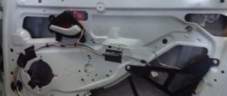
How to remove the Lada Granta ECU step by step instructions
In order to remove the Lada Granta ECU, you will need to perform the following procedure:
- De-energize the system by removing the terminals from the car battery
- The ECU controller is located under the glove compartment under the passenger's feet and hidden under the upholstery. The upholstery is attached to the body on the right with a self-tapping screw. We unscrew this screw.
- Next, we move the sheathing away from the floor with our hands as shown in the figure.
- Now we bend the soundproofing material to the side
- After unscrewing the nuts, we move the ECU away from the body.
Now we squeeze the clamp of the wire harness fastening bracket and fold back the bracket.
- We disconnect the connector from the block and similarly disconnect the second harness with wires, after which we remove the ECU from the car. Make the necessary repairs, then install in the reverse order.
For this we need:
Universal adapter KL-Line BM9213 USB MASTER KIT for tuning a car with an injection engine, you will not chip the carburetor with it,
You can read more about it and how to purchase it here. For the adapter, the driver for the virtual COM port for Win XP, Vista can be downloaded here, you can also use another adapter VAG COM USB KKL v409.1 which can be purchased from our partners, this is the one The KK-Line adapter is exclusively in the case and for funny means.
Next, for flashing the chip firmware, we will need ChipLoader 1.96; you can also use the newest version of ChipLoader 1.97.7, and the previous one works smoothly, so I don’t see the need to use the new one.
in the Help > Help tab you will find the User Guide, also go to options and uncheck all the boxes as shown in the figure above. In order for the block to start sewing, it needs to be modified according to the annotations in the User Manual
, everything is carefully described there.
Lada Granta diagram - ignition part
Grant instrument pinout - dashboard diagram
This part is the most difficult. The large number of pins and the miniature size of the terminals greatly complicates the search for the required group:
- 1/2 – connecting blocks for the front electrical harness;
- 3/4 – similar for the feed harness;
- 5 – lighting control unit;
- 6 – ignition switch module;
- 7 – on-board computer;
- 8 – lever for switching the position of the wipers;
- 9 – tidy;
- 10 – control of emergency modes;
- 11 – cargo compartment lid lock;
- 12 – diagnostic connector;
- 13 – block for the air intake drive;
- 14 – button to turn off the heated rear windshield;
- 15 – emergency contact;
- 16 – brake light switch;
- 17/18 – contact group – output to radio equipment (radio tape recorder);
- 19 – rotating equipment module;
- 20/41 – driver/passenger airbag drive;
- 21 – horn power supply;
- 22 – mounting block group;
- 24 – cigarette lighter group;
- 25 – backlight for stove control;
- 26 – interior lamp;
- 27 – contact group of the ignition switch;
- 28 – controller;
- 29 – incoming connector to the rear of the on-board network;
- 30 – electronic part of the gas pedal;
- 31 – additional resistor;
- 32 – stove motor;
- 33 – heater switch block;
- 34 – door lock module;
- 35/36 – cooling system head fan relay;
- 37 – compressor relay wiring;
- 38 – additional relay or reverse indication coil;
- 39 – air conditioner switch button;
- 40 – automatic transmission drive;
- 42 – evaporator thermometer;
- 43 – output to the rear wiring harness.
Grant ECU pinout
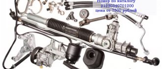
The Lada Granta uses two types of electronic engine control units. Fundamentally, the systems differ slightly, which excludes the possibility of their interchangeability.
| Contact | 11183-1411020-51/52 | 11186-1411020-21/22 |
| A1 | DPKV | |
| A2 | Not involved | |
| A3 | Entering the first knock sensor | |
| A4 | Not used | |
| IN 1 | DPKV | |
| AT 2 | Not involved | |
| AT 3 | Input of the second knock sensor | |
| AT 4 | Main relay output | Not used |
| C1 | Empty | |
| C2 | DTV | |
| C3 | Mass air flow sensor | |
| C4 | UDC | |
| D1 | DDC weight | |
| D2 | Empty | |
| D3 | DTOZH | |
| D4 | Not applicable | |
| E1 | Zeroing the TPS | |
| E2 | Empty | CAN L |
| E3 | Empty | CAN H |
| E4 | Canister purge valve output | |
| F1 | Body from DTV | |
| F2 | Speedometer input | |
| F3 | Not applicable | DFM |
| F4/G4/H4/J4 | Output from injector No. 1/2/3/4 | |
| G1 | Antifreeze temperature sensor ground | |
| G2/G3 | Not used | |
| H1 | On-board electronics grounding | |
| H2 | UDC | |
| H3 | Not involved | Battery charge indicator output |
| J1 | Terminal No. 15 from the ignition switch | empty |
| J2 | Entrance No. 2 TPS | |
| J3 | DDC | |
| K1 | Supplying voltage to the TPS | |
| K2 | Entrance No. 1 TPS | |
| K3 | UDC | |
| K4 | DDK heater power connector | |
| L1/M1 | Leads to the ignition coil ¼ and 2/3 cylinders respectively | |
| L2/M2; L3/M3 | Not involved | |
| L4/M4 | Throttle actuator pin 5/6 | |
What kind of ECUs are there on Kalina?
Below is a table with engine controllers that were installed on the Lada Kalina.
| Manufacturer | Model | vendor code | Engine | Throttle |
| BOSCH | 7.9.7 | 21114-1411020-40 | 1.6l, 8 cl. | Mechanical |
| BOSCH | 7.9.7 | 1183-1411020-20 | 1.6l, 8 cl. | Mechanical |
| ITELMA | January 7.2 | 11183-1411020-22 | 1.6l, 8 cl. | Mechanical |
| BOSCH | 7.9.7 | 11194-1411020-10 | 1.6l, 16 cl. | Electric |
| Avtel | January 7.2 | 11183-1411020-21 | 1.6l, 8 cl. | Electric |
| Elvar | January | 11183-1411020-52 | 1.6l, 8 cl. | Electric |
| Avtel | January M73 | 21114-1411020-41 | 1.6l, 8 cl. | Mechanical |
| ITELMA | ITELMA | 21126-1411020-08 | 1.6l, 16 cl. | Electric |
What types of ECUs are available to Granta and what is the principle of their operation?
Sometimes the Lada Granta model is identified with an exclusive car. Why is she given such status? It's simple. "Lada" has a unique control unit, which is called "Itelma 11186-1411020-22" and cannot be combined with previous modifications of "VAZ". The primary difference of this module is the integrated “CAN bus”. Previously produced models used the “K-channel” to ensure the transmission of pulses. If you set out to experiment and replace the Itelma with a similar device with functionality in the K-channel, then in the end the devices on the panel will certainly “fall asleep”.
Where is the ECU located and what is its operating principle? It is based on a special type of algorithm, the formation of which occurs on the basis of software pre-integrated into memory. This allows the module to process signals from all sensors present in the ECM in real time.
“Itelma 11186-1411020-222”: from stock firmware to chip tuning?
The dilemma associated with the rationality of performing firmware on the “native” software in the ECU excites the minds of many owners.
Here it is worth highlighting the optimized dynamic firmware version for the 1.6-liter 8-valve Lada Granta, which has the “M74” module and meets the toxicity standard according to “E2”.
What preferences does this firmware have? After performing a certain list of manipulations and returning the ECU to its rightful place, optimization of the parameters of fuel supply and ignition distribution is observed. Also, one of the purposes of the firmware is to ensure that the settings of the throttle assembly are adjusted.
Chip tuning allows you to physically disable the 2nd DC (“lambda”) in combination with the catalyst. The implementation of such firmware leads to an increase in the dynamic capabilities of LADA Granta.
The role of the stock firmware is to form the parameters characteristic of normal driving conditions. Let us remind you that the “native” version of the firmware is included in the warranty package. Self-correction of the firmware version without any alternative leads to the cancellation of warranty coverage.
Today, so-called commercial versions of firmware software are available to the mass consumer, including the following:
- “AY_I484GG30”, the product is intended for the 1.6-liter 8-valve Granta modification with the present control module “M74 11186-1411020-22”;
- “I484GI06-STR”, software is offered for Grant with similar motors and blocks in version “11186-1411020-22”, plus compliance with the Euro-2 standard;
- “AY_484GP12”, the firmware is used with controller versions “M74 11186-1411020-22” and motors that comply with “E3/E2” regulations.
A selection of circuit diagrams that facilitate independent repair of the Lada Granta, troubleshooting and diagnosis if any problems occur in the circuits of the car’s electronic components.
Grant relay diagram
Relay location in the main mounting block located in the engine compartment:
- 1 – drive of the cooler of the cooling system;
- 2 – central locking protection;
- 3 – secondary starter relay;
- 4 – additional part of the relay;
- 5 – turn signal and emergency signal breaker relay;
- 6 – wiper drive protection;
- 7/9 – insertion of high/low headlight modes;
- 8 – horn protection element;
- 10 – heated aft windshield;
- 11 – main relay block;
- 12 – fuel pump relay.
Detailed diagram of the VAZ Grant (dashboard)
The vehicle is supplied to the market with a 32-pin instrument panel as standard. The standard pinout of the Grant shield has only 26 pins involved. Residual connectors are provided for the possibility of adding equipment or custom modifications:
- 1 – to the low oil pressure sensor in the engine crankcase;
- 2 – to the handbrake indication switch;
- 3 – intended for service needs when diagnosing the instrument panel;
- 4 – to external lighting switches;
- 5/6 – similar for right and left turn signals, respectively;
- 7/8 – CAN L/H;
- 9 – indication of seat belt position;
- 10 – contact of the Reset button of the steering column lever;
- 11 – response of the brake fluid reservoir sensor;
- 12/13 – on the head optics, high/low beam position;
- 14/15 – foglight terminals front/rear, respectively;
- 16/18 – receiving immobilizer antenna signal;
- 17 – ground wire of the instrument panel;
- 19/21 – to terminal No. 30/15;
- 20 – for the drive of the electric power steering unit;
- 22 – for door closing sensors;
- 23/24 – MK buttons for forward and reverse, respectively;
- 25 – for an environmental thermometer;
- 26 – gas tank float indication.
P O P U L A R N O E:
Sound signaling device for duplicating warning lamps in the vehicle dashboard with a two-tone signal.
The car's audible alarm is designed to duplicate with a two-tone signal all emergency and "turn" warning lamps of the car, as well as signaling when the on-board voltage exceeds 17V.
Alphanumeric marking of inductors and chokes
The data provided below will be useful to radio amateurs when repairing inexpensive radios and radios of Chinese and other models.
Using inexpensive and accessible chips NE555, LM3915 and 7805, you can make a simple engine speed tachometer for a car using 10 LEDs.
The LED tachometer can be used for a car with an on-board voltage of 12V or 24V.
Lada Granta: wiring diagram for rear wiring harness devices
The rear part of the car wiring is responsible for the equipment of the stern and sides of the car. all additional equipment is connected exclusively through this part of the highways:
- 1/2 – contact group for the dashboard;
- 3/4 – direction indicators;
- 5 – handbrake indicator;
- 6 – rear window heating contact;
- 7 – interior lamp;
- 8 – indicator of the driver’s seat belt position;
- 9 – cargo compartment illumination lamp;
- 10 – fuel pump drive;
- 11/15 – aft dimensions for the left and right sides;
- 12 – trunk lid lock drive;
- 13 – button for turning on the interior lamp;
- 14 – additional stop chain;
- 16-19 – door terminal blocks for the rear left, rear right, front left and front right doors;
- 20 – airbag control drive;
- 21 – contact group of license plate lights;
- 22 – on the dashboard;
- 23/24 – rear speed indicator sensors;
- 25/26 – seat belt pretensioners;
- 27 – group of dashboard contacts.
Preventive measures
In order for the factory wiring of the Lada Grant to serve for a long time and not break, experienced experts strongly recommend following a number of simple rules.
- Periodically check all contact connectors and terminals for oxidation and rust. Such damage to the connections can cause a short circuit and a critical decrease in the conductivity of the line, which is perceived by the on-board computer as an error or breakdown.
- Use only original consumables and electronic components. The use of counterfeit products does not guarantee the functionality of the circuit. At the same time, some elements, when damaged, cause a voltage drop in the network, which becomes a direct cause of failure of other equipment or a fire.
- Use special oil to treat contact groups. The fluid is sold in auto shops or electronics stores. After treatment, the contacts are covered with a moisture-impermeable layer, which increases their service life by 2-3 times.
- Carefully monitor the charge level and condition of the battery. The wiring of the Lada Granta critically perceives a significant voltage drop in the on-board circuits. As a result, this may cause damage to the firmware of electronic control units.
Prevention
As a measure to prevent breakdowns, experienced specialists recommend periodically performing maintenance on electrical circuits. This requires a complete review of all wires and disconnectors twice a year for damage to the braiding and oxidation of copper contacts. Damaged parts or loose joints must be replaced with new ones.
Also, advice from “experienced” motorists speaks of the rationality of treating parts with special dielectric oil - this prevents air and moisture from entering sensitive areas and significantly increases the service life of devices.
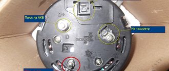
Connector pinout January 7 2
I would like to immediately convey a special greeting to the designer of AvtoVAZ, who came up with this arrangement of this block. In my opinion, I can't think of a worse place. See for yourself.
The ECU is located under the glove compartment under the passenger's feet and hidden under the upholstery. The upholstery is attached to the body on the right with a self-tapping screw.
- If your interior heater (radiator) leaks, the antifreeze will go straight to the control unit, causing almost 100% failure. Even though the Lada Granta is initially equipped with a good quality imported Visteon radiator.
- As you correctly noted, water can get in from under the hood. The rubber plugs on the Lada Granta are not of very good quality, so when they dry out, water will flow onto the controller. To prevent this from happening, check the condition of the rubber plug.
- If the drainage hole (which is shown in the video below) becomes clogged, water may flow into the cabin.
Source
Assignment of contacts of Bosch M ECU 1. 5 . 4, MP 7. 0 and January‑5. 1
Note: In the second column, missing elements in the ECM January 5 are highlighted in blue. 1 . 2, which does not use an adsorber and an oxygen sensor. In the third column, elements of the Euro-3 system that are absent in Euro-2 are highlighted in red
We draw your attention to the fact that this website is for informational purposes only and under no circumstances is it a public offer defined by the provisions described in Part 2 on page 437 of the Civil Code of the Russian Federation.