Do-it-yourself suspension spring replacement
Due to compression and stretching, the spring dampens unevenness, potholes on the road, as well as vibrations of the car body. Since the springs take the heaviest impacts, they often burst, although this is very difficult to detect until it is removed. Experienced drivers can guess the problem by bumps in potholes, car pulls, or noise in the chassis. Replacing a suspension spring with your own hands is not difficult if you follow the preliminary steps. With the appropriate equipment, it is accessible even to beginners.
Let's consider the stages of removing and replacing the front and rear suspension springs of a car. The procedure is similar for almost any car brand.
Photo report on replacing the front suspension springs of a VAZ 2106
If the integrity of the springs is damaged, chips or cracks appear on them, as well as in cases where the springs noticeably sag, it is necessary to replace them.
You can do this on your own. Signs of spring sag:
- a noticeable distortion of the front part of the body appears;
- there is a noticeable difference in the height of the front and rear parts of the body;
- decreased smoothness;
- obvious traces of mutual impacts of the turns are revealed.
Tools required for work:
- hammer;
- screw and hydraulic jacks;
- bologna;
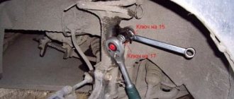
- keys at 6, 13, 17, 19 and 22;
- metal brush.
Causes of failure
Many people are interested in why such a metal part wears out. And there may be several reasons for this:
- Metal fatigue;
- Surface wear;
- End of service life of the part;
- Damage to geometry;
- Collision with stones and other third-party objects;
- High level of load when driving on poor-quality road surfaces;
- Strong compression (when the coils practically touch each other);
- The spring rusts due to contact with road salt;
- Part overload;
How do you know when shock absorbers need to be replaced? Everything is very simple, a strong squat of the machine indicates wear of the part.
The work of replacing the front suspension springs of the VAZ 2106 takes place in several stages:
- Preparation: We tear off the wheel mounting bolts in the area of the planned work with a bologna. After this, use a screw jack to lift the side of the car where the problem appeared and remove the wheel.
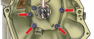
- Removing the shock absorber. You will need keys 6, 13, 17 and 19. While holding the rod from turning, loosen the nuts and remove them. Remove the spring washer and the cushion washer, as well as the upper mounting cushion. We also dismantle the spring washers and nuts securing the bracket to the lever.
Using the mounting hole in the lever (bottom), remove the shock absorber.
Dismantling of other components. It is necessary to loosen the nuts holding the lower arm on the axle (just loosen, it is not worth removing them yet). A hydraulic jack is installed under the lower control arm to level it and also to provide load to the suspension.
We remove the stabilizer bar, dismantle the stabilizer bracket (after unscrewing the nuts holding it) together with the elastic cushion. We remove the ball joint. By loosening the nut holding the pin in the ear of the steering knuckle, we can remove the lower ball joint. We knock out the support pin. To do this, lower the jack and, tapping the lower ear of the steering knuckle with a hammer, knock out the support pin.
Providing access to the front suspension spring. After removing the lower ball joint, there is no longer a need to load the suspension, but the jack will still come in handy. With its help, we will hold the lower arm until we finish working with it. Now unscrew the ball pin nut completely, and then carefully lower the lower arm down. Using a mounting spatula, hold the stabilizer to the side so as not to catch it on the studs on which the bracket is attached. After this we remove the jack.
Now, using a wire or a reliable rope, we raise the upper lever as high as possible, opening access to the spring. Using a mounting tool, we pry up the lower edge of the spring, carefully remove it from the support cup, and remove the gasket from there. Now you can remove the suspension spring. Replacing the front spring. We fix the gasket on the new spring (for this you can take regular electrical tape), install the spring in the required place. Using a mounting blade installed in the hole for the shock absorber and supporting the spring, we fix the lower coil. The correct position of the spring can be determined using the screw surface on the surface of the lower arm and given it to the spring using the same mounting blade. We install the jack under the lever, creating a load for the new spring, and finally seat the spring on the screw surface of the lower arm.
While maintaining (and even increasing) the load on the spring, we use a mounting spatula to secure the stabilizer bar with the bracket studs.
We carry out the assembly in the same way, only in reverse order.
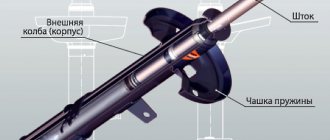
Shock absorber operating principle
During smooth compression of the shock absorber, the liquid located under the piston experiences compression, but due to practical incompressibility, it is forced to flow from cavity B of the working cylinder into a cavity of lower pressure. The fluid moves in two directions. Most of the liquid flows through the eight holes K, lifting the bypass valve plate, pressed by a weak spring sprocket, into the cavity L (the movement of the liquid is shown in figure a by thin arrows). The liquid displaced from cavity B does not completely flow into cavity A; part of it, equal to the volume of the rod inserted into the shock absorber, exits into cavity C through two grooves T in the compression valve body.
When the rod is pressed sharply, the fluid pressure under the piston in cavity B increases, as a result of which the compression valve opens and compresses the spring (fluid movement is shown by bold arrows). The liquid flows into the upper cavity A of the working cylinder in the same way as during a smooth compression stroke. During the compression stroke, the bypass valve has virtually no effect on the hydraulic resistance developed by the shock absorber. The required resistance required during sudden compression is provided by the compression valve.
During the reverse stroke, i.e. when the piston moves upward (recoil stroke), liquid from the upper cavity A of the working cylinder through holes P in the piston and four cutouts H of the throttle disk (the rear shock absorber throttle disk has six cutouts) flows into the lower cavity B of the working cylinder. The volume of liquid displaced from cavity A is less than the released volume of cavity B under the piston by the amount of the volume of the rod removed from the shock absorber. The freed volume is filled with liquid coming from cavity C through the holes P of the compression valve, which lifts the intake valve plate, pressed in the plane of the compression valve by the legs of a weak spring sprocket (the movement of the liquid is shown in Figure b by thin arrows).
During the recoil stroke, when the car body is thrown up on the elastic elements of the wheel suspensions, the pressure above the piston in cavity A of the working cylinder increases. The liquid through the holes P in the piston presses on the recoil valve discs and bends them. At the same time, the valve spring, which supports the discs, is compressed, and the flow area for liquid flow increases. The required hydraulic resistance to dampen vibrations during the recoil stroke is provided by the calibrated spring of the recoil valve. Cavity B during sharp recoil is filled in the same way as during smooth movement of the piston. The intake valve does not significantly affect the hydraulic resistance during shock absorber operation; it is designed for free admission of fluid into cavity B.
Replacing the front suspension spring
Replace the spring if there is mechanical damage or significant settlement. Signs of precipitation:
– deterioration in smoothness, frequent breakdowns of the suspension;
– visible distortion of the front part of the car or a significant difference in the height of the front and rear parts that appeared during operation;
– strongly pronounced traces of the collision of the spring coils.
You will need: keys “22”, “13” (two), a screw (hydraulic) jack, a wrench for wheel bolts, a wire brush, a hammer.
According to their length under a load of 4413 N (450 kgf), springs are divided into two groups: group A - length greater than 232 mm; group B – length equal to or less than 232 mm. The springs are marked with paint on the outside of the coils: group A - with yellow paint; group B – green. The upper and lower coils of the spring are the same.
Install springs of the same group on the left and right of the car. Replace springs in pairs and together with gaskets.
When removing and installing springs, use extreme caution to prevent the spring from “firing” from the suspension assembly and causing injury. The proposed method of removing a spring without special tools requires certain skills. It is optimal to use any special spring puller from those available commercially.
1. Remove the wheel and shock absorber (see “Replacing the shock absorber”).
2. Loosen the two nuts securing the lower arm to the axle.
3. Place a jack under the lower arm and lightly load (pressing the spring through the lower arm with a jack) the suspension to make it easier to disconnect the stabilizer.
4. Unscrew the two nuts securing the stabilizer pad bracket and remove the washers.
5. Remove the bracket and pad from the stabilizer.
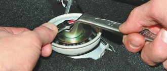
6. Loosen the nut securing the lower ball joint pin to the steering knuckle and unscrew it until it aligns with the end of the pin. Remove the jack.
7. Apply several sharp blows with a hammer to the outer surface of the lower ear of the steering knuckle until the hinge pin comes out of it.
To make it easier to press out the pin, use one of the commercially available pullers.
8. Place a jack under the lower arm again without loading the suspension.
9. Unscrew and remove the pin nut. Carefully lowering the lower arm, slightly unload the suspension and use a mounting blade to move the stabilizer bar through the studs securing its bracket. Completely unload the suspension. Remove the jack.
10. Secure the upper arm (without disconnecting it from the steering knuckle) with a wire hook in the highest possible position for better access to the spring.
11. Using a spatula, carefully pry the spring from below and remove its lower end from the lower support cup on the lever.
12. Remove the spring from the vehicle.
13. Remove the spring gasket from the upper support cup on the body.
14. Secure the new gasket to the new spring (for example, electrical tape).
Surface a of the spring gasket, in contact with the spring coil, is made of a screw (b – the beginning of the screw surface).
During installation, it is necessary to ensure that the beginning of the screw surface of the gasket b coincides with the end c of the spring coil.
15. Install the spring with the gasket on the body. While holding the spring, insert the mounting blade into the hole for installing the shock absorber and secure the lower coil of the spring with the blade. Orient the spring so that the end a of the lower coil after its installation coincides with the beginning b of the screw surface on the lever.
16. Place the jack under the lower arm and, lightly loading the spring, use a mounting blade to guide the lower coil of the spring onto the screw surface of the lower support cup.
17. Having increased the load, move the pin on the bracket fastening to the stabilizer. Make sure the spring is installed correctly. Using a mounting blade, move the stabilizer bar through the stud and continue installing the parts in the reverse order of removal.
Instead of using the method shown or using a special spring puller, you can use universal spring clamps.
Install the ties on the spring without catching them on the last turns, and tighten the spring as much as possible, its installation will be much easier.
Install the spring into the upper support cup.
Raise the lower arm, align the spring with the helical surface of the arm, place a jack under the arm and lightly load the spring. Loosen the ties through the spring coils and remove them down through the shock absorber mounting hole in the lower arm. Continue work on assembling the suspension.
Tighten the nuts securing the lever to the axle when the suspension is loaded with the weight of the vehicle (on an inspection ditch or overpass). When working on a lift, place a support under the lower arm and lower the vehicle slightly (when working on a platform, raise the arm with a jack) so that the position of the arms approximately corresponds to their position under load. After replacing the spring, check and, if necessary, adjust the wheel alignment angles. Use the services of workshops with special equipment.
Shock absorber device
The shock absorber consists of a steel reservoir 4 (29) connected by welding to the lower mounting eye 1; Inside the tank, a working cylinder 13 (30), made of a steel pipe, is freely placed. From below, a compression valve is pressed into the working cylinder (all the way to the end), which consists of a housing 2, a valve 39 inserted into it with a spring 40 and a valve seat 3. The valve seat is screwed into the body; its position is selected in advance according to the given hydraulic characteristic of the compression valve, and then is controlled by a limit nut 38, which, in turn, has a collar that serves as a stop for the spring sprocket 6, which presses the intake valve plate 5 towards the plane of the compression valve.
Rod 14 (23) is made of carbon steel. The working surface of the rod 14 of the front shock absorber is coated with a layer of chrome and polished. Rod 23 of the rear shock absorber is polished without coating with a layer of chrome. At the upper end of the rod 14 of the front shock absorber there is a groove cut for the locking ring 20, which secures the thrust ring 21.
The upper end of the rod 23 of the rear shock absorber is welded by contact welding to the upper mounting eye 22, and a casing 28 is welded to the flange of the eye, protecting the rod and seals from direct contact with dirt and moisture. At the lower end of the rod, a nut 37 secures the piston 32 with the parts of the recoil valve and bypass valve.
The recoil valve includes a throttle disk 10 (33), covering eight piston holes located along the circumference closer to its axis, a disk 9, a set of thin adjusting washers 35, a plate 31, a calibrated spring 8 (36), a nut 37, screwed in until it stops, and set of adjusting washers 7.
The bypass valve consists of a restrictive plate 12 with a washer, a spring sprocket 11 and a plate 31 that closes the bypass holes of the piston, located along the circumference further from its axis.
The working cylinder is closed on top by a rod guide 15 made of zinc alloy. Inside the guide there is a metal-ceramic bushing along which the rod moves. The felt seal 26, located under the reservoir nut, protects the internal cavity from the penetration of dirt, and the internal rubber seal 27, installed in the holder 19 and pressed by the spring 16 through the holder 18, prevents fluid from leaving the shock absorber. To seal the tank, a sealing gland 17 is placed between the cage and the rod guide, which is compressed through the fiber washer 25 when the nut 24 is tightened.
Worth reading:
- Using a rope or wire, pull the upper arm higher, thereby providing access to the front suspension spring.
- Use a pry bar to pry the lower end of the spring and remove it from the lower arm support cup.
How to change a support bearing without a wheel alignment on a Lada Kalina
Replacing the support bearing on Kalina without removing the strut is impossible, or will not be correct, but replacing the part without further camber is still possible. In this case, the technology for removing the rack will change:
- After removing the wheel, unscrew the hub lock nut.
- Disconnect the steering knuckle from the ball joint and steering rods.
- Then we remove the steering knuckle from the CV joint with the strut and shock absorber spring, this way you will not break the camber bolts.
Also check out
- Remove the suspension spring, remove the spring gasket from the upper support cup. After this, you can replace the front suspension spring.
To do this, do the following:
- Use electrical tape to secure the gasket to the spring and install the part in place.
- Place the blade in the hole for the shock absorber, supporting the spring with it, and fix the lower coil. There is a screw surface on the lower arm that indicates the correct position of the spring. Installation should achieve this position
- Having installed the lower coil in the correct position, jack up the lever and load the spring. Using a mounting spudger, seat the spring onto the screw surface.
- Increase the load on the spring, install the stabilizer bar between the two studs that secure the bracket.
- Reassemble everything in reverse order.
After this, the replacement of the VAZ 2106 suspension springs can be considered complete.
You can check it out:
When to change
The service life of the “supporters” is on average 50-100 thousand km, depending on the conditions in which the car is used. Replacing the timing belt on a vw passat b3 1.8 rp. Video how. After this resource has expired, it is recommended to change them. How to change the front strut support on a viburnum, replacing the support bearing: catalog of materials. Correct replacement of the stabilizer bar on a Ford Focus. The front suspension arm of the VAZ 2110 is attached to the hub with the front struts of the VAZ 2110. Replacement. Replacing cushions The video shows a detailed process of replacing engine cushions on a VAZ 2110. Replacement is also necessary if any defects are detected.
Lada Kalina - front strut support bearing: choice, price, characteristics
If you do change the support bearing individually by installing it in the old support, then you should buy from trusted manufacturers, a summary table of which and photographs are presented below. Catalog number (article) – 1118-2902840.
Table of recommended manufacturers
| No. | Manufacturer | Manufacturer's code | Price 2016, rub. | Equipment | ||
| Peculiarities | Retaining rings | Protective cap | ||||
| 1 | VBF Russia Analogue | 1118-2902840-01 | 700 | – Clip made of hardened steel; – Manufactured according to GOST; – Increased service life; – High-quality lubricant. | – | – |
| 2 | NPP "System Technologies" Russia Analogue | SS10113/11180-2902840-00 | 900 | – Silence; – Vibration damping; – Work at low temperatures; – Protection from dirt and dust. | – | – |
| 3 | AvtoVAZ Russia Original | 1118-2902840 | 750 | – Original product; – 1 year warranty; – Durability. | – | – |
Table of bearing sizes 8112Н and technical characteristics
| Characteristic | Unit | Value according to GOST (TU) |
| Inner diameter of the tight ring, d | mm | 60 |
| Outer diameter of the tight ring, d1 | mm | 85 |
| Free ring inner diameter, D1 | mm | 62 |
| External diameter of free ring, D | mm | 80 |
| Installation height | mm | 17 |
| Dynamic load capacity | kH | 41,5 |
| Static load capacity | kH | 95,0 |
| Nominal speed | rpm | 3600 |
| Axial clearance | mm | – |
| Steel type | – | SHH-15 |
| Hardness of steel and rollers | H.R.C. | 61-65 |
| Contact angle | hail | – |
| Torque | kN*M | 220 |
| Ring roughness | Ra | 0.32 |
| Number of balls | PC. | 24 |
| Ball diameter | mm | 8,731 |
| Mounting chamfer radius, r | mm | 1,5 |
| Weight | G. | 295 |
Drawings of universal threaded ties
Let's return to the question of how to make a device for tightening shock absorber springs yourself. Below is the appearance of the finished devices:
Factory-made threaded ties
On one side of the rod there is a left-hand thread, on the other - a right-hand thread. The standard thread pitch is M18. But buying threaded rods is not enough here. And to cut the thread yourself, you will need special equipment.
Drawings of the components that make up the entire structure are shown here:
Threaded tie (3 parts)
To make parts, you need a lathe, drilling and, probably, milling machine. It may be easier to contact a workshop. Print the drawing by downloading it from the website.
Most likely, there are no other drawings of universal ties on the Internet. And what is shown above is taken from a book on repairing domestic cars. You can use it.
Let's say the ties were made according to the drawings and all the parts fit together. But even then the advice about using lubricant remains valid. You need to take solid oil or cyatim and apply this material to the threads of the nuts.
Packaging cyatim-201, 20 gr.
Cyatim-201 lubricant is a rather expensive material. You can reduce consumption by mixing it with machine oil in a 50/50 ratio. Good luck.
can I wedge in? If the puller is in the form of separate 2-3 staples, then it’s not fun. The staples have a bad tendency to slide along the coils of the spring all in one direction, the spring bends in an arc, like a shot, and where it will fly after that and on what fingers it will hit the head is unknown. I squeezed the spring and placed it next to the car, I turned behind the car, at that moment it shot and jumped above the roof of the house, I pressed my head into my shoulders and waited for where it would fall: on my head or the roof of the car, it fell on the barn.
We cook the screeds ourselves
In general, it makes sense to make shock absorber spring ties yourself. How to do this is discussed further.
Four nuts and two threaded rods
The metal products listed below are easy to find in almost any supermarket. For example, you can buy two M16 threaded rods. You will also need four extended nuts, as well as a steel plumbing pipe. Its internal diameter is 16-16.5 mm.
The end result is what is shown in the pictures. You will also need a steel rod, which is used to make reinforcement. Let's look at how screeds are made:
- Two identical cylinders are cut from the pipe, the length of which is 80-120 mm;
- Threaded rods can be shortened if necessary;
- 8 rods approximately 30 cm long are made from reinforcement;
- Using any bending equipment, the rods are bent to obtain hooks;
- Four rods are welded to two nuts, another four - to pipe sections;
- The set of components is completely ready for use at this stage.
Drawings of universal threaded ties
Let's return to the question of how to make a device for tightening shock absorber springs yourself. Below is the appearance of the finished devices:
Factory-made threaded ties
On one side of the rod there is a left-hand thread, on the other - a right-hand thread. The standard thread pitch is M18. But buying threaded rods is not enough here. And to cut the thread yourself, you will need special equipment.
Drawings of the components that make up the entire structure are shown here:
Threaded tie (3 parts)
To make parts, you need a lathe, drilling and, probably, milling machine. It may be easier to contact a workshop. Print the drawing by downloading it from the website.
Most likely, there are no other drawings of universal ties on the Internet. And what is shown above is taken from a book on repairing domestic cars. You can use it.
Let's say the ties were made according to the drawings and all the parts fit together. But even then the advice about using lubricant remains valid. You need to take solid oil or cyatim and apply this material to the threads of the nuts.
Packaging cyatim-201, 20 gr.
Cyatim-201 lubricant is a rather expensive material. You can reduce consumption by mixing it with machine oil in a 50/50 ratio. Good luck.
We cook the screeds ourselves
In general, it makes sense to make shock absorber spring ties yourself. How to do this is discussed further.
Four nuts and two threaded rods
The metal products listed below are easy to find in almost any supermarket. For example, you can buy two M16 threaded rods. You will also need four extended nuts, as well as a steel plumbing pipe. Its internal diameter is 16-16.5 mm.
The end result is what is shown in the pictures. You will also need a steel rod, which is used to make reinforcement. Let's look at how screeds are made:
- Two identical cylinders are cut from the pipe, the length of which is 80-120 mm;
- Threaded rods can be shortened if necessary;
- 8 rods approximately 30 cm long are made from reinforcement;
- Using any bending equipment, the rods are bent to obtain hooks;
- Four rods are welded to two nuts, another four - to pipe sections;
- The set of components is completely ready for use at this stage.
It is easier to weld by placing the workpieces on a plane. The essence of these words is illustrated by the picture:
How to weld hook rods
Actually, what follows is a film where the technology is shown “inside and out”. The author even solved the problem with the lack of a bending machine: to bend one rod, you need two similar rods welded to a steel profile.
If the reader thinks that using welding is difficult, then it is better not to take risks. Welded joints can withstand significant loads, but only if they are performed according to all the rules. Spring ties can be made without welding. A suitable drawing is given below.
Two ties in 10 minutes (video)
What is a puller
Shock absorber spring pullers are a special device that can be used to compress the springs of a shock absorbing element. After compressing the element, you can continue the dismantling activities that have begun. There are many options for the device in question. We may be interested in the simplest version of a removable device.
The object in question is two slats made of metal.
The entire length is threaded. There are hooks installed along the edges of the product, which, when turned, move towards each other. In other words, when you need to compress the spring element, you just need to turn the rack. At this moment, the hooks tighten the spring structure.
There is another option for tightening the shock absorber spring struts - a belt.
The design consists of 2 “frogs”, which are tucked into durable belts made of fabric. They are thrown onto the upper coil of springs. After this, you need to work with the “frogs”, alternately clicking on each of them.
The process of the movements performed involves gradual tensioning of the belts, tightening them into a spiral. After compression, the workflow continues.
A device for tightening shock absorber springs is sold in automobile stores and on the Internet. Its cost is high, as is its quality.
Photo: Factory version with left and right threads, pitch M-18.
The elements do not fly off and do not hit the car owner in the forehead during disassembly. But some drivers “with hands and head” make pullers with their own hands.