The VAZ 2106 rear axle gearbox is the main device that transmits the generated power from the engine to the wheels. This design is used on almost all domestic Soviet-style cars. It has proven itself to be a fairly strong part, but breakdowns still occur.
Timely and high-quality maintenance will help to extend the service life as much as possible.
Despite the fact that there are a large number of cars on which the gearbox is installed, in most cases its structure is the same. Its main task is to transfer force from one device to another. At the same time, the speed of its movement can change the intensity and direction. This is the main purpose of the device in the rear axle system.
Important nuances in work
- When driving the oil seal using a mandrel, do not overdo it. Apply gentle blows and control the depth of the oil seal. If you hit it hard, you can easily damage the oil seal;
- Before installing the oil seal, lubricate the rim and sealing edge with fresh oil;
- Before installation, inspect the flange for wear in the area where the sealing lip of the oil seal meets. If there is a “groove,” the flange must be replaced.
As you can see, the process of replacing the VAZ 2107 gearbox seal is quite simple and does not take much time. The most important thing in this job is to properly tighten the rear axle flange nut.
Features of VAZ-classic rear axle gearboxes
All VAZ classic cars are rear-wheel drive, the vehicle moves using the rear axle, which is the drive axle. The VAZ rear axle gearbox is the most important part in the transmission; it is where the main gear is located.
A lot depends on the gearbox - if it is faulty and humming, the car can get stuck in the middle of the road at any moment and will have to be towed. The speed of the car depends on the gear ratio (TR) of the main pair in the rear axle gearbox (REA) - the lower it is, the faster the car will move. But too high a speed loads the engine and transmission, so when replacing REM, owners of VAZ 2101-07 vehicles need to take into account the power and volume of the internal combustion engine (ICE), and install a gearbox that optimally matches the technical characteristics of the vehicle.
Device
In order for the car to move, it is necessary to transfer the rotation of the engine to the wheels. But the engine speed is too high, and in order to correctly distribute the torque, a mechanism is needed that changes the gear ratio. Due to the gearbox and different engine speeds, the speed of movement changes, and the main pair of the rear axle takes over the rotation and transmits it to the wheels through gears.
The VAZ rear axle gearbox consists of the following parts:
- flange, it is fixed on the drive gear (shank) of the RZM, and is an intermediate link between the driveshaft and this gear;
- the shank of the main pair, at one end of which there are splines for pressing the flange, at the other end there is a bevel gear with a small number of teeth;
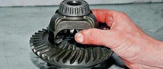
- driven gear (planet gear), it is in mesh with the drive gear, and it is with it that it forms the main gear;
- center differential, allowing the rear wheels to spin at different angular speeds.
The differential design is very simple - the mechanism consists of two axle gears, two satellites and a satellite pin. From the gearbox, the movement is transmitted to the axle shafts, on which the wheels are mounted.
Differences in VAZ rear axle gearboxes
RZMs differ in the gear ratio of the main pair; in total, there are four types of gearboxes on the VAZ classic:
The slowest one is the RZM 2102, its drive gear has 9 teeth, and the driven gear has 40 teeth. To calculate the gear ratio, you need to divide the number of planetary gear teeth by the number of teeth on the drive shaft; for the VAZ 2102 the drive gear is equal to 4.44.
The “penny” gearbox (2101) accordingly has the number of teeth on the gears 10/43, so its IF is 4.3. The next, faster one is RZM 2103 - it has a ratio of 10/41, which means the gear ratio is 4.1. And finally, the “fastest” will be the 2106 gearbox, with the number of teeth 11/43 and an inverter frequency of 3.9, respectively.
Many VAZ 2101-07 owners strive to install the fastest gearbox, but this is not always necessary. If the car often carries cargo, that is, the car is a “workhorse”, high speed is of no use, but high-torque power will be very useful. It should be noted that RZM 2102 was not supplied as spare parts; it was installed only on station wagons.
Gearboxes on machine 2107
The VAZ 2107 is the last car from the rear-wheel drive VAZ series - it began production later than all of them and was in production the longest of all the “Classics”; its production ended in 2012. All types of gearboxes were installed on the machine, except 2102; the choice of RZM depended on the type and power of the engine.
Rear axle specifications
In terms of the design and characteristics of the leading axes, all classic Zhiguli cars are the same. The only difference is in the ratio of the main pairs.
Table: characteristics of the rear axle "six"
| Parameter | Factor |
| Serial part number | 21062402010 |
| Length, mm | 1400 |
| Crankcase diameter, mm | 220 |
| Hopper diameter, mm | 100 |
| Weight without wheels and oil, kg | 52 |
| Tool type | hypoid |
| Gear ratio | 3.9 |
| Required amount of lubricant in the crankcase, cm 3 | 1,3-1,5 |
Why does oil leak from the rear axle gearbox of VAZ 2107, 2106?
It is important to understand when the seal is leaking and when there is simple fogging. If after using the machine no drops of oil are visible near the oil seal, we can assume that the oil seal is simply sweating
In a situation where drops of oil or a trail followed by a drop are visible, we can assume that the oil seal is leaking.
Causes of leakage of the rear gear axle seal of VAZ 2107, 2106:
- Wear of oil scraper elements of the oil seal.
- Rupture of the compression spring of the oil seal.
- Oil seal defect.
- Development on the flange.
- Faulty or clogged gearbox breather.
When the oil seal is just sweating on a VAZ gearbox, you don’t have to change it, but if it leaks, then it definitely needs to be changed! But before changing the oil seal, check whether the gearbox breather is working by simply pressing on its head, and it should move a little. If it is motionless, then the breather is most likely to blame for the leak, because. it does not allow gases to escape from the gearbox, which creates excess pressure and presses the oil out of the oil seal. Also try unscrewing and blowing out the breather before deciding to replace the gearbox seal. Let's now talk about replacing it.
Oil seal replacement process
First you will need to arm yourself with the necessary tools. In particular, you need to prepare:
- flat screwdriver;
- calipers;
- a regular mount or some convenient strong metal rod;
- keys for 13 and 24;
- torque wrench;
- dynamometer;
- durable cord.
On a VAZ 2106, the rear axle oil seal is replaced after the oil is drained from the crankcase. In this case, you must not forget about the oil drain cap, which should be screwed into place.
Removing the axle shafts
Let's get started:
both rear axle shafts will need to be removed from the rear axle beam.
To do everything correctly, you need to strictly follow the instructions. So:
- dismantle the wheel;
- remove the brake drum;
- we see four nuts that will need to be unscrewed (to avoid problems, you will need to turn the axle shaft until the large diameter holes coincide with the two brake shield locking nuts):
- unscrew the nuts;
- remove the spring washers;
- turn the axle flange 90 degrees so that the large-diameter holes and the brake shield mounting nuts coincide;
- We secure the brake drum with two wheel bolts (you can tighten them by hand).
Note. These wheel bolts do not need to be tightened, leaving approximately 5 mm to ensure acceleration of the drum. But you need to be extremely careful not to damage the brake drum.
The axle shaft is abruptly removed from the rear axle beam.
Advice. There is a special impact puller that will allow you to remove the axle shaft much faster.
Special impact puller for removing axle shafts
Removing the old cuff
After both axle shafts have come out, you need to do the following:
- holding the cardan from turning with a pry bar (see Repairing the cardan on your own) from turning, unscrew the four nuts securing the hinge flange;
- remove the bolts;
Replacing the rear axle oil seal on a VAZ 2106
- disconnect the flanges using a flat-head screwdriver;
- now you need to wind a strong cord, which was stored in advance, onto the flange of the drive gear (when winding it, you need to make several turns and wind it);
- We use a dynamometer to check the moment of resistance to turning or the RPM of the drive gear (this value must be remembered or written down).
Note. MSP is the product of the dynamometer readings, expressed in kgf, and the force application lever, expressed in cm.
- Now you will need to unscrew the flange mounting nut, holding the drive gear with a special wrench;
- remove the flat washer.
Advice. There is a special wrench to hold the pinion flange. You can even make it yourself from a piece of metal pipe of the required size and two bolts and nuts.
Homemade key for holding the pinion flange
Replacement of the oil seal in the rear axle of the VAZ 2106 continues:
- the drive gear flange is removed;
- we find the drive gear oil seal and remove it from the neck using a screwdriver;
- install a new cuff.
Installation
Note. Before installing a new oil seal, you need to lubricate its working edge with Litol-24.
Light blows with a hammer through a special frame will help to correctly install the oil seal in place.
It is recommended to watch this video, where everything is described in detail.
https://youtube.com/watch?v=_MHYhEGwT84
Note. It must be remembered that the new oil seal should be pressed into the gearbox housing to a depth of 2 mm, counting from the end of the gearbox housing. As a mandrel, you can use some old bearing, or rather its ring, or even a piece of pipe of a suitable size and diameter.
- put the drive gear flange in place;
- put the required washer;
- tighten the flange mounting nut, while holding the drive gear with a special wrench.
Note. The tightening torque of the nut must be equal to a certain value depending on the resistance torque of the drive gear. When tightening the nut, you should start with a smaller torque and periodically check the resistance torque. If, at the moment of tightening the nut, it is discovered that the moment of resistance is too excessive, then this indicates unacceptable deformation. You will have to replace the bushing by disassembling the gearbox and then adjusting the engagement of the main gears. It will be difficult to carry out such work on your own; a highly qualified specialist is needed.
We assemble all the components and parts in reverse order.
The oil seal replacement process is complete. During the process, you should try to compare the methods for dismantling and installing a new oil seal with photos and diagrams. It is not difficult to carry out this operation with your own hands; it will be enough to follow the advice and notes given in the instructions. Replacing it yourself will help you avoid unnecessary expenses and save a lot of time, because at good car services there is now a long queue and the price of services is high.
Which gearbox to choose: 2103 or 2106
How many kilometers to break in a new car? How long should a car break-in take?
In the “nature” of Zhiguli gearboxes there are 4 types:
- VAZ 2101 - gear ratio 4.3
- VAZ 2102 - 4.4
- VAZ 2103 “troika” - 4.1
- VAZ 2106 “six” - 3.9.
The gear ratio is the ratio of the teeth, for example, in a “six” gearbox the large gear is marked 2106 1143. Therefore, to determine the pair, 43/11 = 3.9 is necessary. The larger the number of the pair, the more high-torque the car will be, but it will lose maximum speed. Most often, you can find two types of gearboxes in stores: with a pair of 4.3 and 3.9.
Work order:
- We hang up the rear axle, drain the oil from the crankcase, remove the wheels and brake drums, and remove the axle shafts. We disconnect the driveshaft from the drive gear flange and move it to the side.
- Using a “13” wrench, unscrew the eight bolts securing the gearbox housing to the rear axle beam.
- Remove the gearbox assembly.
- We install the new gearbox in the reverse order of removal. Apply sealant to the threaded part of the crankcase mounting bolts. After installation, do not forget to fill the rear axle housing with 75W-90 transmission oil. Crankcase volume is 1.3 liters.
Problems when paying with bank cards
Sometimes difficulties may arise when paying with Visa/MasterCard bank cards. The most common of them:
- There is a restriction on the card for paying for online purchases
- A plastic card is not intended for making payments online.
- The plastic card is not activated for making payments online.
- There are not enough funds on the plastic card.
In order to solve these problems, you need to call or write to the technical support of the bank where you are served. Bank specialists will help you resolve them and make payments.
That's basically it. The entire process of paying for a book in PDF format on car repair on our website takes 1-2 minutes.
If you still have any questions, you can ask them using the feedback form, or write us an email at
Reasons for replacing the oil seal and symptoms of malfunction
The seals in the gearbox are changed for one reason: they begin to leak. The oil seal may become old, tear, or be of poor quality from the very beginning, which will inevitably affect its service life. In addition, the tightness of the gearbox may be compromised due to improper installation, as a result of which the seals are compressed too much. The malfunction can be identified by the following signs:
- Small drops of oil appeared on the rear axle, near the gearbox.
- After leaving the parking lot, an oil stain remains on the asphalt.
- A small radial play appeared on the gearbox shank.
It is easy to determine: just move the shank up and down with your hands. As a rule, such play indicates not only torn oil seals, but also worn bearings. It is there that you can detect the backlash
Article on the topic: Do-it-yourself repair and restoration of car batteries
Changing the oil in the rear axle of a VAZ 2106
Often, car enthusiasts who own a vehicle such as the VAZ 2106 ask the same question. They are interested in which oil fluid is best suited for the rear axle of their car. At the same time, they ask - what volume is needed and how to change the oil?
There are different opinions. But experts recommend filling the rear axle gearboxes of this machine with transmission oil, which is marked 80W90. For example, this is Lukoil 80W90 GL. This group of oils also includes TAD-17 80W-90 or the so-called TNK.
When we've sorted out the oil, it's time to answer another question. Perhaps he is one of the most important. Namely, how much oil is required? So, the oil volume is as follows - 1.3 liters. At the same time, it is possible to change the oil in the gearbox. True, in this case you will need 1.4 liters.
As for the interval, it is necessary to change the oil fluid after every 30,000 kilometers of the vehicle. If you convert the mileage into a time frame, you get 3 years of operation.
The oil fluid is replaced in accordance with the established procedure:
- First of all, you need to use a lift or inspection hole. You will also need a key for “seventeen” and a hexagon for “twelve”.
- Next, unscrew the drain plug in the bridge and place a special container designed for draining the oil fluid. At the same time, the filler plug is also unscrewed. This is necessary so that the oil fluid flows out faster.
How to change the oil in the rear gearbox of a VAZ. Video
It would be a good idea to treat all components with washing liquid.
- ratchet crank;
- set of heads;
- twelve hexagon;
- two slotted screwdrivers;
- hammer;
- jack;
- wheel bolt wrench;
- mandrel for installing the oil seal;
- penetrating lubricant;
- container for collecting oil;
- torque wrench;
- digital or mechanical scales;
- fresh oil to the rear axle.
- We drive the car into the pit and unscrew the propeller shaft mounting bolts, having previously made a mark on the flank of the cardan and gearbox. After unscrewing the cardan, we tie it with a wire so that it does not interfere.
Using a special wrench, we secure the flange from turning and, using a wrench or a twenty-seven socket, unscrew the nut. The key for fixing the flange is shown in the photo below. You can also screw two universal joint mounting bolts into the flange and insert a powerful screwdriver between the bolts.
Unscrew the plug and drain the oil from the rear axle.
We remove the flange from the slots and take out the thin ring behind it using two screwdrivers.
Using two screwdrivers, remove the inner race of the bearing. We take out the spacer sleeve. This bushing is needed to create the correct tension in the bearings
Please note that the belt of the bushing you removed is barrel-shaped, but on the new bushing it is straight. At the moment of tightening, the belt is wrinkled and the correct tension is achieved.
The photo below shows a new bushing and one that was already working.
We install a new bushing, with the narrow side facing the trunk. We also install the ring.
How to check the rear axle
Naturally, noises such as hum, vibration, crackling or knocking can also occur due to other malfunctions. For example, the same driveshaft, if the outboard bearing breaks or the crosspiece fails, can make a crunching sound and vibrate. Failure of the elastic coupling of the universal joint is also accompanied by similar symptoms. The rear struts or other suspension elements may be knocking. In any case, before starting to repair the bridge, it is important to make sure that it is the one that is faulty.
Checking the rear axle is performed as follows:
- We drive out onto a flat section of the road without holes or ledges.
- We accelerate the car to 20 km/h.
- We listen and note the accompanying noises.
- We gradually increase the speed of the car to 90 km/h and remember at what speed this or that uncharacteristic sound occurs.
- Without turning off the gear, release the accelerator pedal, reducing the engine speed. We continue to monitor changes in the nature of the noise.
- Again we accelerate to 90–100 km/h, turn off the gear and ignition, letting the car coast. If the extraneous noise does not disappear, the rear axle gearbox is in order. Without load, it cannot make noise (except for the bearings). If the sound disappears, the gearbox is probably faulty.
- We check the tightness of the wheel bolts by tightening them with a wheel wrench.
- We install the car on a horizontally flat surface. We hang its rear wheels with a jack so that we can rotate them freely.
- We alternately rotate the wheels of the car left and right, and also push them back and forth to determine the play. The wheel should turn easily without jamming. If the wheel plays or slows down when the bolts are securely tightened, the axle bearing is most likely worn out.
- When the gear is engaged, we rotate each of the wheels around its axis. Let's look at the behavior of the cardan shaft. It should also spin. If it doesn't turn, the axle shaft is most likely broken.
Video: extraneous noises in the rear of the car
Replacing the axle shaft
Let's look at the process of replacing the axle shaft, its bearing and oil seal in detail. Tools you will need:
- wheel wrench;
- a jack and a safety stand (in extreme cases, a stump or a few bricks);
- wheel stops;
- reverse hammer;
- wrenches 8 mm, 17 mm;
- slotted screwdriver;
- Bulgarian;
- round nose pliers;
- hammer;
- chisel;
- workbench with a vice;
- blowtorch or gas torch;
- spacer made of wood or soft metal;
- a piece of steel pipe with a wall diameter of 33–35 mm;
- Litol type lubricant;
- dry clean rag.
Removing the axle shaft
To dismantle the axle shaft, you should:
Place the car on a flat surface and place chocks under the front wheels. Use a wheel wrench to unscrew the wheel bolts. Raise the car body with a jack. Unscrew the wheel bolts and remove the wheel. Using a size 8 wrench, unscrew the drum guide pins. Remove the drum
If it does not come off the blocks, carefully knock it down using a spacer and a hammer. Using a 17mm wrench (preferably a socket), unscrew the nuts (4 pcs) securing the axle shaft. They are located behind the flange, but you can access them through specially provided holes by turning the axle shaft. Using round-nose pliers, remove the spring washers that are located under the axle nuts. Disconnect the axle shaft from the rear axle by pulling it towards you
If it does not give in, use a reverse hammer. To do this, the tool flange must be screwed to the axle flange with wheel bolts. By sharply moving the hammer weight forward, knock out the axle shaft. If you don't have a reverse hammer in your tool arsenal, you can use a removed wheel instead. It needs to be screwed with the back side to the axle shaft flange and struck with a hammer on the tire from the inside until the axle shaft comes out of the casing. Remove the axle shaft assembly with the bearing and its retaining ring. Remove the sealing gasket located between the brake shield and the axle shaft flange. Using round nose pliers or pliers, remove the oil seal from its seat.
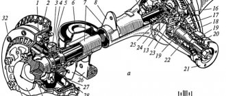
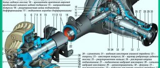
Rear axleThe rear axle structure is shown in Fig. 3-43.
Rice. 3-43. Rear axle: 1 — axle shaft; 2 — wheel mounting bolt; 3 - guide pin; 4 — oil deflector; 5 — brake drum; 6 — axle bearing; 7 - locking ring; 8 — flange of the rear axle beam; 9 — axle shaft seal; 10 — rear axle beam; 11 — bearing mounting plate; 12 — rear brake shield; 13 — axle guide; 14 — adjusting nut; 15 — differential box bearing; 16- bearing cover; 17 — breather; 18 — satellite; 19 — driven gear; 20 — axle gear; 21 — adjusting ring of the drive gear; 22 — spacer sleeve; 23 — drive gear bearings; 24 — oil seal; 25 — mud deflector; 26 - flange - 27 - oil deflector; 28 — rear axle gear housing; 29 — drive gear; 30 — satellite axis; 31 — adjusting washer; 32 — differential box.
Removing and installing the rear axle
Removal and installation of the rear axle beam are described in the chapter <Rear Suspension>. To remove the rear axle, it is enough to disconnect the suspension rods and shock absorbers only from the rear axle beam.
When installing the rear axle, tighten the nuts of the rod mounting bolts in accordance with the instructions in the chapter <Rear Suspension>.
After installation, bleed the brake system and adjust the service and parking brake systems according to the instructions in the <Brakes> section.
Fill the TAD-17 and the rear axle with oil through the oil filler hole.
Dismantling and assembling the rear axle
Disassembly. Remove the pipeline with the brake system tee from the bridge, while disconnecting the ends of the tubes from the brake wheel cylinders.
Place the axle on a repair bench and drain the oil from the crankcase.
After removing the brake drum and unscrewing the nuts securing the brake shield, use a puller 67.7801.9516 (Fig. 3-44) to remove the axle shaft assembly with the oil deflector, the axle shaft bearing mounting plate, the bearing and the lock ring. Remove the brake shield and O-ring. If replacement is necessary, remove the oil seal from the axle beam flange.
Perform the same operations on the other end of the beam, then remove the gearbox.
Reassemble the rear axle in the reverse order of disassembly. Wherein:
; — lubricate the threads of the gearbox mounting bolts with sealant, having previously degreased them and the threaded holes in the rear axle beam;
— coat the axle bearing seal with LITOL-24 grease before installation;
; — when installing the oil seal into the beam flange, use mandrel A.70157.
Rice. 3-44. Pressing out the axle shaft using puller 67.7801.9516; 1 - axle shaft; 2 - impact puller.
— lubricate the seating belt of the axle shaft under the brake drum and the surface of the axle shaft flange in contact with the drum with graphite grease or LSC-15 grease.
Install the brake drums after installing the rear axle on the vehicle and securing the cable ends to the parking brake drive levers.
Checking the rear axle beam
Carefully check the technical condition of the beam, especially when repairing a car that has been involved in an accident. A deformed beam can cause rear axle noise and accelerated tire wear.
The deformation of the bridge beam is checked in both horizontal and vertical planes.
Having attached flange A.70172 to each end of the beam, install the beam with flanges on identical prisms located on a test plate at least 1600 mm long so that the contact surface of the crankcase to the beam is in a vertical plane.
Check the deformation of the beam by placing a square against the outer (Fig. 3-45) and side (Fig. 3-46) surfaces of the A.70172 flange; if the beam is not deformed, the square will fit tightly.
The amount of deformation is checked with a feeler gauge. If the 0.2 mm feeler gauge passes on any flange, the beam must be straightened
Using a square (Fig. 3-47), check the perpendicularity of the gearbox mounting surface relative to the supporting surface of the A.70172 flange. The 0.2 mm probe should not pass through.
Rotate the bridge beam 90° and install it on the prisms. The square applied to the outer surface of the flange (Fig. 3-48) must fit tightly, otherwise check the amount of deformation with a feeler gauge. The 0.2 mm probe should not pass through.
Rice. 3-45. Checking vertical deformations of the rear axle beam using a square on the outer surface of flange A. 70172.
Rice. 3-46. Checking the torsion of the rear axle beam using a square along the side surface of flange A. 70172.
Rice. 3-47. Checking the perpendicularity of the gearbox mounting surface.
Rice. 3-48. Checking horizontal deformations of the rear axle beam using a square on the outer surface of flange A. 70172.
If the deformation exceeds the specified value, straighten the beam following the instructions below.
After making all the adjustments, thoroughly rinse the beam, clean the magnetic plug, replace it and check:
— quality of welds and beam tightness;
— cleanliness inside the beam (no burrs, chips and oil residues) and cleanliness of the beam breather.
After this, paint the outside of the beam to protect it from corrosion.
Editing the rear axle beam
Attach A.70172 flanges to each end of the beam (used when straightening, not when checking beams) and install it on the supports of the hydraulic press so that the ends of the clamping crossbar 2 (Fig. 3-49) are in the deformation zone of the beam. The most likely location of the deformation zone is at a distance of 200-300 mm from the ends of the beam flanges.
Rice. 3-49. Scheme for straightening the rear axle beam: 1 - hydraulic cylinder; 2- clamping beam; 3 — flange A.70172; 4 - square; 5 — press table; 6 — emphasis; 7 — indicator stand.
Install the stand 7 with the indicator so that the indicator leg rests against the upper part of the side surface of the flange, and the indicator arrow stands when checking the beam. On the other side of the beam, install either a stand with an indicator or a square 4.
Having installed limit stops 6 under the beam (in the deformation zone), use a hydraulic press to straighten the beam sequentially in the horizontal and vertical planes, monitoring the straightening results using an indicator or a feeler gauge using square 4.
The maximum press force when straightening the beam should not exceed 98,000 N (10,000 kgf) so that excessive deformation of the casing section does not occur.
Note. With a stop height of 6, selected experimentally, the beam can be straightened without checking with a square or indicator
Remove the beam from the press and check it as indicated above, replacing the A.70172 flanges with <check> ones.
In the absence of proper equipment, as an exception, it is allowed to edit the rear axle beam sequentially on each side, but with the obligatory check of beam deformation on both sides (see <Checking the rear axle beam>).
Half shafts Removal and installation
Remove the wheel and brake drum.
Having unscrewed the nuts securing the brake shield to the bridge beam, using a puller 67.7801.9516, holding the brake shield, remove the axle shaft along with the oil deflector, the bearing mounting plate and the bearing lock ring.
If replacement is necessary, remove the oil seal from the beam flange. Reinstall the oil seal using mandrel A.70157.
Install the axle shaft in the reverse order of removal, being careful not to damage the working edge of the oil seal. Before installing the brake drum, lubricate the seating belt of the axle shaft and the flange surface in contact with the drum with graphite grease or LSC-15 grease. After installation, check the operation of the axle shafts under road conditions.
Checking technical condition
Check the technical condition of the parts included in the axle shaft kit and make sure that:
— the ball bearing is not worn out or damaged; if the axial clearance in it exceeds 0.7 mm, replace the bearing;
— the locking ring and bearing have not been displaced relative to the original fit; if the inner ring of the bearing rotates relative to the seat of the axle shaft, replace the locking ring;
— the bearing mounting plate and the oil deflector are not damaged;
— the axle shaft is not deformed and the seating surfaces are not damaged; The runout of the axle shaft, measured at the centers on the journal under the oil seal, should not exceed 0.08 mm. Before installing into the centers, thoroughly clean the centering holes on the axle shaft from dirt and rust.
If wear or damage to parts installed on the axle shaft is detected, replace them with new ones, following the rules below and using special tools. Eliminate slight bending of the axle shaft by straightening. After straightening the axle shaft, the runout of the flange end, measured at the centers, should not exceed 0.05 mm. If the runout of the flange end is more than specified, but not more than 0.08 mm, then it is allowed to groove it to eliminate the end runout. Reducing the thickness of the flange due to its groove is allowed by no more than 0.2 mm.
Removing the locking ring
Removing and installing the axle bearing lock ring must only be done using a hydraulic press.
Half rings of device A.74108//? Cover the bearing and install the axle shaft vertically so that the half rings rest on the thrust ring.
Place the axle shaft under the press (Fig. 3-50) and apply gradually increasing force to the splined end of the axle shaft until the bearing lock ring is removed. Do not reuse the axle bearing lock ring, but replace it with a new one.
Check whether the seating surface of the axle shaft has any marks or damage; if necessary, replace the axle shaft with a new one.
Rice. 3-50. Pressing out the axle bearing lock ring using tool A. 74108/R: 1 - tool A. 74108/R; 2- axle shaft.
Axle shaft assembly
Place the axle shaft vertically, resting its flange on ring 4 (Fig. 3-51) (A.74107/JR) of the device.
Install the axle bearing oil deflector and the bearing mounting plate with a gasket on the axle shaft, pre-connected with two screws; Install the axle ball bearing.
Insert the new locking ring into the special holder 7, place it in the oven and heat the ring to approximately 300 °C so that at the time of pressing onto the axle shaft its temperature is 220-240
Rice. 3-51. Pressing in the axle bearing lock ring: 1 - mandrel A. 74107/2 R; 2 - bearing lock ring; 3 — bearing mounting plate and oil deflector assembly with gasket; 4- support ring A. 74107/R; 5- axle shaft; 6 — bearing; 7-holder A.74107/4 R:
Press the locking ring onto the axle shaft using mandrel 1 on a press with a force of no more than 58800 R (6000 kgf) so that the inner bearing ring is clamped between the locking ring and the shoulder of the axle shaft.
After pressing, make sure that the ring does not move under an axial load of 196,000 N (2,000 kgf). For this purpose, install the axle shaft assembly on fixture A.95601//? (Fig. 3-52) and clamp the locking ring in a special vice.
Place the indicator leg with a division value of 0.01 mm to the axle shaft flange. After setting the indicator arrow to <0>, apply the indicated axial load, using a torque wrench to create a tightening torque of 78.4-83.3 N.mm (8-8.5 kgf.m) on the fixture screw. The screw rests through the ball against the end of the axle shaft. In this case, even the smallest gap should not appear between the lock ring and the inner ring of the bearing.
After removing the load and unscrewing the screw of the device, the indicator arrow should return to the zero position; this proves that no movement has occurred between the lock ring and the axle shaft. If the indicator arrow does not return to the zero position, then the locking ring has moved and the axle shaft assembly must be replaced with a new one.
Rice. 3-52. Checking the force with which the axle bearing lock ring is pressed out using tool A. 95601/R and a torque wrench: 1 - indicator; 2 - axle shaft; 3 — device A. 95601/R; 4 - torque wrench; 5-ball bearing; 6 — bearing lock ring.
Measuring the axial free play of the axle shaft on a car
The axial free play of the axle shaft can be measured on a vehicle both with the wheel and brake drum removed and without them removed. In the first case, the measurement is more accurate. For what:
— remove the caps from the rear wheels and loosen the bolts securing them;
— put stops under the front wheels and hang the rear axle;
— release the parking brake and set the gear shift lever to neutral;
— remove the wheels and brake drums;
— screw device 02.7834.9504 to the axle shaft (Fig. 3-53);
— pass the extension of the indicator leg 1 through one of the two large holes of the axle shaft until it stops in the brake shield or in the oil deflector and secure the indicator;
— take measurements with an indicator, applying a force of about 49 N (kgf) to the axle flange in both directions along the axis of the rear axle. Free play should not exceed 0.7 mm.
Measure the free play of the axle shaft without removing the wheel and brake drum as described above, taking into account the following features:
Rice. 3-53. Measuring the axial play of the axle shaft with the wheel and brake drum removed: 1 - indicator; 2- device 02.7834.9504.
— secure device 02.7834.9504 using one of the holes for the wheel bolts;
— pass the leg of the indicator extension through another hole for the wheel bolt;
— the force applied to the wheel along the axis of the rear axle should be about 98 N (10 kgf), the free play of the axle shaft should be up to 0.7 mm.
Read interesting articles about the VAZ2106 car...
A little anatomy
In the last years of its life on the AvtoVAZ assembly line, the classic Zhiguli remained perhaps the only passenger car in the world with a rigid drive axle. This design is simple and technologically advanced in production, but has serious disadvantages in operation:
- large unsprung mass of the bridge, which negatively affects the smoothness of the vehicle;
- tendency to steer when one of the wheels hits an obstacle - at this time, due to the misalignment of the bridge, both wheels tilt from the vertical and tend to roll in the direction of the tilt;
- reduction in the useful volume of the trunk, because there must be free space between the axle and the car body for the axle to move during the compression of the suspension.
The advantage of a rigid axle, in addition to manufacturability, is its better adaptability to bad roads: the ground clearance under the axle practically does not change depending on the load, and the wheel drive is reliably protected from external influences by the axle housing.
The Zhiguli bridge consists of a stamped-welded bridge beam (such beams are called “Banjo” for their characteristic shape), a main gearbox with a differential, and axle shafts. The gearbox is made in a separate open housing, the flange of which is bolted to the crankcase. A drive gear with a driveshaft mounting flange and a differential with a driven wheel are mounted in the housing on bevel bearings. The main gears are hypoid, that is, their axes are located at an angle of 90 degrees to each other, but do not intersect (they are crossed). The amount by which the axis of the drive gear is offset relative to the axis of the driven gear is called hypoid offset. Such a transmission, if it is precisely manufactured and well adjusted, operates smoothly and with the least noise, but due to the intense sliding of the curved teeth, it is very sensitive to the quality and quantity of oil in the bridge.
The design of the bridge is relatively simple and technologically advanced, although it is not without its drawbacks
Defects in the gearbox
Increased play in the RZM can be formed due to wear of the differential pinion pin - if you grab the driveshaft and rotate it clockwise and counterclockwise, this play can be felt. Also, increased clearance can be formed due to wear of the splines inside the differential housing itself.
If the gaps in the main pair of gearboxes are not adjusted, a characteristic noise occurs when the car moves:
- when the load increases (sharp acceleration), a characteristic howl is heard in the bridge;
- When I let off the gas the noise goes away.
The engine can hum in a different way, but the characteristic feature described above can most often be heard on VAZ classic cars. Worn teeth of the main pair are clearly visible on the planetary gear - they become rounded, and they often show traces of rust.
↑ Adjusting the gaps
We adjust the gap in the main pair and preload the differential bearings simultaneously, in several stages:
- tighten the nut from the side of the driven gear until the gap in the mesh is completely eliminated;
- Using a caliper we measure the distance between the covers;
- screw the second nut until it stops and tighten it by 1-2 teeth of the nut. The distance between the covers should increase by approximately 0.1 mm;
- By rotating the first nut, we set the required gap in engagement of 0.08–0.13 mm. This is minimally noticeable play in the engagement, accompanied by a slight knock of tooth against tooth;
- We control the constancy of the gap in the engagement with our hands and gradually tighten both nuts until the distance between the covers increases by 0.2 mm. This will ensure the necessary bearing tension.
Slowly turn the driven gear three turns and at the same time feel the play in the meshing of each pair of teeth.
If it is uniform in all gear positions, then install locking plates.
A decrease (increase) in play in any sector indicates deformation of the differential housing and the need to replace it or trim it on a lathe.
There are two types of locking plates: single-claw or double-claw.
Depending on the position of the nut slot, we install one of them.
Let's go to the store
So we did everything we could, but the leak didn't stop. This means it's time to change the seal. Actually, according to GOST, these products are called “Reinforced rubber cuffs for shafts.” Or simply - cuffs. If a store offers you a part with that name, don’t be surprised. Factory part designation: 2101–2402052. Further, its variations can be written through a dash: -01, -02 and so on. All of these products are interchangeable and differ in the nuances of their design and manufacturer.
Perhaps the most important thing when choosing an oil seal is the manufacturer. Choose products from famous factories
No name details, in principle, should not attract your attention, because not only according to ours, but also according to Western standards, the cuff must be marked with the manufacturer’s trademark, cuff size, and type of material. Domestic GOST also provides for marking the year of manufacture. As a rule, these are two digits of the year when the mold was made, and next to them are dots, each of which indicates one year of operation of this equipment. You count the points, add their number with the numbers and find out in what year your part was manufactured. The year of manufacture is important because over time, any rubber compound “ages”, losing its shape and elasticity.
The type of mixture from which the oil seal is made is also important. The most expensive and most durable - fluorine rubber
It works well in aggressive environments and at high temperatures. It is usually marked with the Latin letters FBR. Nitrile butadiene rubber (NBR) is considered optimal in terms of price and quality for automobile transmissions. ACM acrylate polymer seals are also available, but they are usually used in components that should not be directly exposed to water. Chemists are constantly improving their products, so the fundamental differences between mixtures are becoming less and less, due to additives introduced into them that improve the weaknesses of certain recipes. Read reviews on the Internet, listen to the seller’s recommendations and make a decision based on your financial capabilities.
When examining externally, first of all pay attention to the quality of the working edge: it should be even and smooth around the entire circumference. You can use a magnifying glass
It will be a big plus for the gearbox seal to have an external boot - like a second edge, but without a spring and with a hole of a slightly larger diameter. The boot, as the name suggests, protects the work area from dust and dirt. The presence of an inclined notch on the boot or near the working edge indicates that the oil seal is designed for shafts rotating in the same direction.
Signs of gearbox problems
The rear gearbox is one of the reliable mechanisms of classic Zhiguli cars and breakdowns rarely occur with it. However, like any other unit, it may have its own malfunctions, which are determined by characteristic symptoms. They are worth dwelling on in more detail.
Noise when accelerating
If during acceleration there is an extraneous sound from the gearbox installation site, then it can be caused by:
- worn out or incorrectly adjusted differential bearings. It will require dismantling, disassembling and diagnosing parts with subsequent adjustment;
- Incorrect meshing of the teeth of the main pair gears. Eliminated by proper adjustment;
- lack of lubrication in the gearbox. The lack of oil in the crankcase is restored, after which it is checked for leaks at the places where the sealing elements are installed.
Noise when accelerating and braking the engine
If noise occurs both during acceleration and during braking by the power unit, there may not be many reasons:
- deterioration or failure of the bevel gear bearings of the main pair. Eliminated by replacing failed elements;
- Incorrect adjustment of the gap between the tip and the planetary gear. The mechanism needs to be diagnosed and replaced with damaged parts, as well as setting the required gap between the gear teeth.
↑ Diagnostics of gearbox parts
We thoroughly wash the gearbox parts in kerosene and carefully inspect them. If at least one tooth is damaged (chipping, waves, scratches, scuffs on the working surfaces), we replace the gears with new ones.
The edges between the tops and working surfaces of the driven gear teeth must be sharp. If the slightest nicks or roundings are visible, replace the main pair with a new one.
Minor damage to the satellite axle, axle pinion journals and their mounting holes can be eliminated with fine sandpaper followed by polishing.