From the point of view of modern environmental requirements, carburetor engines are already outdated. But cars with carburetors feel great on our roads. Yes, they do not correspond to the spirit of the times, but they work conscientiously and will continue to work for a very long time.
That is why the VAZ 2107 carburetor is a very popular unit today. Those who drive a “classic” can service and repair it themselves; there is nothing supernaturally complicated there. On modern foreign cars, stuffed with electronics, do-it-yourself repairs are no longer possible.
Purpose, diagram, structure and principle of operation of the VAZ 2107 carburetor
The “seven” was equipped with various modifications of the DAAZ 2107 carburetor (Dimitrovgrad Automobile Unit Plant). They are all similar in principle and differ only in some design details.
Diagram of the VAZ 2107 carburetor structure: (1 - screw for adjusting the stroke of the accelerator pump intake valve; 2 - carburetor cover; 3 - fuel jet of the transition system of the second chamber; 4 - air jet of the transition system; 5 - air jet of the econostat; 6 - fuel jet of the econostat; 7 — main air jet of the second chamber; 8 — emulsion jet of the econostat; 9 — pneumatic drive of the throttle valve of the second chamber; 10 — small diffuser; 11 — jets; 12 — discharge valve of the accelerator pump; 13 — accelerator pump nozzle; 14 — air damper; 15 - main air jet of the first chamber; 16 - starting device jet; 17 - automatic starting device; 18 - idle air jet; 19 - idle fuel jet; 20 - fuel supply needle valve; 21 - fuel filter; 22 - fuel supply fitting ; 23 — float; 24 — screw for factory adjustment of the idle speed system; 25 — main fuel jet of the first chamber; 26 — adjusting screw for the quality of the working mixture; 27- adjusting screw for the amount of carburetor working mixture 2107-1107010; 28 — throttle valve of the first chamber; 29 — carburetor body; 30 — throttle valve of the second chamber; 31 — throttle body; 32 - emulsion tube; 33 — main fuel jet of the second chamber; 34 — accelerator pump bypass jet; 35 — accelerator pump inlet valve: 36 — accelerator pump drive lever; 37 - carburetor pneumatic valve 2140-1107010-70.)
Purpose.
The purpose of the carburetor is to prepare the gasoline-air mixture in the required proportion and supply it to the engine cylinders. The quality of engine operation, power output, and service life depend on how correctly the ratio between fuel and air is maintained, and how well the dispersion is mixed.
Device and principle of operation. The schematic diagram of the VAZ carburetor is conventionally divided into three structural elements:
- Cover with outlets for hoses;
The structure of the VAZ 2107 carburetor cover: (1 - float axis; 2 - needle valve; 3 - float; 4 - gasket; 5 - trigger diaphragm with rod; 6 - spring; 7 - adjusting screw; 8 - trigger cover; 9 - idle fuel jet; 10 — solenoid shut-off valve; 11 — plug; 12 — carburetor cover; 13 — fuel filter; 14 — air damper; 15 — fuel supply pipe; 16 — air damper axis with lever; 17 — control lever fixation ball air damper; 18 — air damper control lever; 19 — lever axis; 20 — bushing for fastening the air damper drive rod) - The housing in which the float chamber and chambers with diffusers are located;
Structure of the VAZ 2107 carburetor body: (1 - accelerator pump diaphragm; 2 - accelerator pump drive lever; 3 - cover; 4 - accelerator pump drive cam; 5 - power mode economizer cover; 6 - economizer diaphragm; 7 - economizer fuel nozzle; 8 — economizer valve; 9 — check valve of the accelerator pump; 10 — accelerator pump nozzles with a fuel supply valve; 11 — nozzles; 12 — main air jets with emulsion tubes; 13 — main fuel jets; 14 — bracket for fastening the air damper drive rod shell; 15 — adjusting screw of the second chamber; 16 — stopper of the adjusting screw; 17 — stopper cap; 18 — adjusting screw for slightly opening the throttle valve of the first chamber; 19 — axis of the throttle valve of the first chamber with drive levers; 20 — locking lever of the second chamber; 21 — lever spring locks; 22 — throttle axis of the second chamber with a lever; 23 — throttle valve of the first chamber; 24 — throttle valve of the second chamber; 25 — plug for adjusting screw of mixture quality (composition); 26 — return spring of the throttle valve drive lever of the second chamber; 27 — adjusting screw for the quality (composition) of the idle mixture; 28 — carburetor body; 29 — adjusting screw for the amount of idle mixture; 30 - electrical wire of the limit switch of the forced idle economizer; 31 - carburetor heating unit) - The bottom where the throttle valves are located.
Now in more detail about the design and principle of operation:
- Using a fuel pump, gasoline is pumped into the float chamber from the tank to a certain level, which is regulated automatically by opening and closing the needle valve;
- Then fuel is pumped from the float chamber through nozzles into the mixing chambers. In this case, the fuel is already divided into small droplets, which are mixed with the air coming from the air intake with an air filter;
- Econostat is a device for enriching the fuel mixture. It turns on when the engine is running under high load and adds additional fuel to the mixing chambers;
Diagram of the econostat and economizer of the VAZ 2107 carburetor: (1 - throttle valve of the second chamber; 2 - main fuel jet of the second chamber; 3 - fuel channel; 4 - main fuel jet of the first chamber; 5 - throttle valve of the first chamber; 6 - vacuum supply channel; 7 — economizer diaphragm; 8 — ball valve; 9 — economizer fuel jet; 10 — fuel channel; 11 — air damper; 12 — main air jets) - Then the mixture of gasoline and air enters diffusers, where droplets of gasoline are crushed and the resulting mixture is finally mixed;
- The finished mixture enters the fuel (intake) manifold through the throttle valves. The amount of air in the fuel mixture is regulated by an air damper, and the volume of the finished mixture that goes into the fuel manifold is regulated by two throttle valves (one for each chamber);
- At high speeds, the accelerator pump turns on.
Diagram of the VAZ 2107 carburetor accelerator pump (1 - nozzles; 2 - fuel supply ball valve; 3 - pump diaphragm; 4 - pusher; 5 - drive lever; 6 - pump drive cam; 7 - first chamber throttle valve; 8 - check ball valve ; 9 — throttle valve of the second chamber) - A separate idle system is provided, which supplies the minimum required amount of gasoline so that the engine runs smoothly and does not overuse gasoline.
A working carburetor does not need any control. The system itself determines in what mode the engine operates, how much fuel mixture to supply and at what moment. But sometimes it is necessary to carry out maintenance of this unit with tuning and adjustment.
Car device
The cars are equipped with a four-stroke carburetor engine with an overhead camshaft. The engine lubrication system is equipped with a full-flow oil filter 30 and is designed for the use of special oils with a complex of additives that provide the oil with high lubricating properties, resistance to oxidation and allow operation in a wide temperature range.
The crankcase ventilation system of a closed type engine ensures the suction of gases from the crankcase into the intake manifold and increases the durability of the engine. Engine cooling is liquid. The coolant is a special one with a low freezing point and a high boiling point, and does not affect metals and rubber. The fluid is filled in at the factory and does not require replacement for two years.
The cooling system is a closed type with a bypass channel and a distribution tank, which compensates for changes in fluid volume and pressure when the engine heats up. The water pump is driven by a rubber V-belt. The thermostat in the cooling system serves to speed up the warm-up of the engine, its intake system and to automatically ensure the thermal conditions of the engine. The tubular-plate radiator (with brass brazed tubes or aluminum prefabricated ones since 1987) is mounted on two rubber pads and is bolted to the front of the body through steel spacers and rubber bushings.
The engine cooling system includes a body heater, into which fluid enters from the cylinder head through a tap and is discharged to the pump. The exhaust system is equipped with three mufflers arranged in series. Connected by clamps, the system components are attached: to the body floor with two rubber belts behind the main muffler housing and with a rubber cushion behind the exhaust pipe.
The power system includes an air filter 5, a thermoregulatory tank, a fuel pump 29 and a carburetor with a pneumatic drive for opening the secondary chamber throttle valve and an electronically controlled forced idle economizer. Depending on the engine installed on the car, different carburetor models are used.
Carburetor 2107-1107010 is installed on a 1.45 liter engine with an ignition distributor with a vacuum regulator. Carburetor 2105-110-7010, which differs from the above in the dimensions of the diffusers and mixing chambers, as well as the adjustments of the fuel metering systems, is installed on VAZ-21072 cars. which use a 1.3 liter engine and a distributor with a vacuum regulator. All carburetors are also distinguished by the presence of a pneumatic valve in the idle system, controlled by an electronic unit. In 1986, VAZ-2107 cars began to be equipped with a carburetor of a new family, model 21053-110-7010, created on the basis of the VAZ2108 carburetor.
The carburetor is equipped with a high-efficiency dry-type air filter, which has a paper filter element with an additional external cleaner made of non-woven synthetic fiber. The fuel tank is located in the trunk, on the right side of the car. The engine cylinder block, clutch housing and gearbox housing are interconnected and form a compact power unit, which is mounted on the car at three points on rubber cushions.
Torque from the engine crankshaft to the driving rear wheels of the car is transmitted through the mechanisms and components that make up the car's transmission. The transmission includes: clutch, gearbox, driveline, final drive, differential and axle shafts. Clutch. The cars are equipped with a single-plate dry clutch with a diaphragm pressure spring, with a torsional vibration damper (damper) on the driven disk.
Depending on the engine installed on the car, two types of clutch are used: 2103 - for cars equipped with an engine with a displacement of 1.3 liters and 1.45 liters. and 2121 - for cars with engines with a displacement of 1.6 liters. The clutch housing type 2121, assembled with the pressure plate and spring, is marked with a mark in the form of a hole with a diameter of 6 mm in one of the slots in the pressure spring lobe. The driven discs differ in the shape and width of the friction linings. Clutch type 2103 has a friction lining width of 29 mm, clutch type 2121 has 35 mm. The latter are riveted with a large number of rivets.
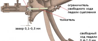
To control the clutch, a foot pedal 23 with a servo spring and a hydraulic release drive with a fluid reservoir installed on the front panel of the vehicle are used. Gearbox 22 has four or five forward gears. All forward gears have synchronizers, which equalize the rotation speeds of the connected parts before turning on the gears. The five-speed gearbox differs from the 4-speed gearbox in the shape of the rear cover and the placement of the fifth stage at the rear end of the secondary shaft. The selection of gear ratios provides the car with confident starting, good acceleration and high efficiency.
Gear shift lever 21 is located on the floor of the body. Depending on the gear ratio of the final drive, the gear ratio of the speedometer drive gears is different. To distinguish it, the speedometer drive is painted: blue for the final drive ratio 3.9, red for 4.1. Cardan transmission 17, consisting of two shafts with an intermediate support and equipped with two cardan joints on needle bearings and a rubber coupling, transmits torque from the gearbox to the main gear. The front driveshaft is connected to the driven shaft of the gearbox through a rubber elastic coupling and a flange that moves along the driveshaft on splines.
The rear propeller shaft is connected to the main gear drive gear with a rigid flange connection. An intermediate elastic support with a ball bearing supports the middle part of the driveline and absorbs its vibration. The main gear, consisting of a pair of bevel gears with spiral teeth of hypoid engagement, increases the supplied torque and transmits it at right angles to the axle shaft. The transmission of torque from the driven gear to the axle shaft occurs through a bevel differential with two satellites. The differential ensures that the driving wheels of the car (left and right) rotate at unequal speeds when cornering.
The front wheel suspension is independent, lever-spring. with coil springs, with double-acting telescopic hydraulic shock absorbers to dampen body vibrations on elastic suspension elements; equipped with a car anti-roll bar and two compression buffers that limit suspension travel. Stamped upper and lower control arms are pivotally connected to a forged steering axle. Two ball joints are placed in housings and attached to the arms with bolts and nuts.
Using rubber-metal hinges, an axle, bolts and nuts, the lower arm is connected to the cross member of the front suspension, mounted on the longitudinal beams (spars) of the body. The upper arms are connected to the load-bearing part of the body using similar rubber-metal hinges and an axle. The suspension coil springs are placed between the lower control arms and the mudguard strut supports. The torsion stabilizer bar, which reduces the lateral tilt of the body when turning and reduces the lateral sway of the body, is connected to the body and lower arms using brackets that cover the rubber cushions of the stabilizer bar.
Hydraulic shock absorbers, located inside the springs, have an eye in the lower part for attachment to the lower arm, and in the upper part there is a rod with a threaded end for attachment to the body. The front wheel hub rotates on two tapered roller bearings mounted on a axle. The rear wheel suspension consists of two cylindrical coil springs with double-acting telescopic shock absorbers, four longitudinal and one transverse rods, two compression buffers located at the ends of the rear axle beam, and one central one located in the middle.
Twisted springs with rubber insulating rings at the top and plastic ones at the bottom rest with their upper end on the body, and their lower end on cups welded to the rear axle beam. The transverse and longitudinal rods are connected to the rear axle beam and the body using conical rubber bushings. steel spacer bushings, bolts, washers and nuts.
Shock absorbers 15 of the rear suspension are installed outside the spring and are attached from above to the body, from below - to the ends of the rear axle beam through conical rubber bushings. Rubber buffers attached to the body floor above the axle beam are designed to soften possible impacts of the rear axle beam that may occur when driving on unimproved roads. A buffer above the front neck of the final drive housing limits the upward stroke of the crankcase, preventing the driveshaft from touching the body floor.
The wheels of the car are disk, stamped. Radial tires with tubes are mounted on the wheels. The front wheels are fastened with four bolts to the hub flanges, the rear wheels - to the axle flanges. Wheel and tire assemblies are balanced statically and dynamically using weights. mounted on the rim. Control mechanisms. which include steering and brakes, serve to change the direction of movement, brake the car and keep it stationary.
The steering consists of a steering mechanism with an intermediate driveshaft and a steering gear that transmits force from the driver to the steered wheels. The steering wheel, through the steering mechanism and drive, turns the front wheels, thereby changing the direction of movement of the car. Features of the steering mechanism are: semi-rigid steering wheel; fastening of the steering shaft bracket, flexible in the event of an accident; a composite steering shaft, the upper part of which rotates on two needle bearings in special rubber bushings, and the intermediate shaft has cardinal joints at the ends, which allows mutual movement of the steering shafts. And finally, an angular contact double-row ball bearing in the steering bipod roller, which reduces the steering effort when turning the wheels.
The steering gear worm gear housing is attached from the inside of the engine compartment to the left side member of the body; on the opposite side, the pendulum arm bracket is attached to the right side member. The steering drive includes two steering linkage levers, a bipod, a pendulum lever and three rods: one middle one and two outer ones. The middle link is solid, has ball joints at the ends for connection with the pendulum arm and the steering bipod. Each extreme rod consists of two threaded tips connected to each other by split adjusting couplings. By rotating them, they change the length of the side rods and adjust the toe-in of the wheels. The adjusting couplings are fixed on the rods with tie clamps. Each of the outer rods has ball joints at the ends for connection to the steering axle arms, pendulum arm or steering arm.
The braking system of a car is used to reduce the speed of movement, stop and hold the car in a stationary state and has two independently operating drives. The service brake system has a hydraulic drive to the wheel brake mechanisms, is controlled by a suspension-type pedal 24 through a vacuum booster 7 and acts on all wheels. Parking and emergency (emergency) braking system - the handbrake control lever 20 installed on the floor between the front seats acts only on the rear wheels. The hand brake has a mechanical cable drive.
The front wheels are disc wheels and consist of a disc and a caliper. The disc is attached to the wheel hub, and the caliper enclosing the brake disc is attached to a bracket mounted on the steering axle. Inside the caliper there are wheel hydraulic cylinders with pistons that transmit force to the pads with friction linings. On some cars, the pads have lining wear indicators. The rear brakes are drum brakes with self-aligning pads, driven by a rear cylinder with two pistons or by a mechanical drive lever. The rear brakes, like the VAZ-2105 models, are distinguished by the design of the lower support of the pads and the automatic adjustment of the gap between the drum and the pads, introduced into the wheel brake cylinders.
The hydraulic brake drive consists of two independent braking circuits (systems) for the front and rear wheels. Therefore, the reservoir has two reservoirs for brake fluid, and the master cylinder has two independent cavities with two pistons. Two independent systems have been introduced for safety: in the event of damage to one of them (liquid leakage and damage to the pipeline), the second remains in operation.
A pressure regulator is installed in the hydraulic drive to the brake mechanisms of the rear wheels, which adjusts the braking pressure of the rear wheels depending on the load on them. The load on the rear wheels depends on the presence or absence of passengers in the rear seat or cargo in the trunk and on the effect caused by braking, in which the load is redistributed along the axles of the car due to inertia: the load on the front wheels increases, on the rear wheels it decreases. The regulator sets the pressure in the brake cylinders of the rear wheels so as to prevent blocking (“skidding” of the wheels, and if blocking occurs, it helps to advance it on the front wheels, which reduces the possibility of the car overrunning).
The regulator is controlled by a torsion lever, which is attached at one end through a shackle to the rear axle, and the other is connected to the regulator piston. The regulator piston limits the pressure in the rear wheel system depending on the size of the gap between the rear axle and the body, which depends on the load on the rear axle of the car during braking.
The electrical equipment of cars is made according to a single-wire circuit, in which the negative terminals of the sources and consumers of electricity are connected to a ground that performs the function of the second wire. The current sources in the system are an alternating current generator 37.3701 from 1987 with a built-in rectifier unit and voltage regulator and a lead-acid battery type 6ST-55P.
The ignition system, which includes an ignition coil, an ignition distributor with a chopper, centrifugal and vacuum ignition timing regulators, high and low voltage wires, spark plugs and an ignition switch, has two circuits: low and high voltage. The low voltage circuit, supplied with current from a battery or from a generator, includes, in addition to current sources, an ignition switch, a capacitor, the primary winding of the ignition coil and a breaker or contactless sensor in a contactless ignition system and a switch that serves to interrupt the current in the primary circuit of the coils ignition with automatic regulation of the period of current accumulation in the coil depending on the crankshaft speed.
The high voltage circuit consists of the secondary winding of the ignition coil, distributor, high voltage wires and spark plugs. The vehicle lighting and light signaling system provides near and far illumination of the road. designation of the vehicle size with signal lights in the parking lot, lighting of instrumentation and interior body lighting, as well as light signaling of the vehicle’s turn and the operation of individual engine and vehicle systems. Two rectangular headlights contain high and low beam lights, side lights and direction indicators.
Halogen lamps with increased luminous efficiency and the headlight's light window area have improved road illumination. The used headlight hydraulic corrector allows the headlight beams to be moved from the driver's seat in a vertical direction depending on the vehicle load, which ensures optimal illumination of the road surface without dazzling drivers of oncoming cars. The headlights are equipped with a cleaning and washing system, controlled by a lever from the driver's seat. Tail lights indicate the vehicle's size at night and have sections for brake light, turn signal, fog light and reverse light.
Exterior lighting and fog lights are turned on by switches on the instrument panel console, and headlights and direction indicators are turned on by levers on the steering column. At the same time, the design of the turn signal switch ensures that the flashing light signals are automatically turned off when the vehicle exits a turn. The interior is illuminated by a lamp attached to the roof of the car, which is turned on by a manual switch. In addition, there are door switches mounted in the front and rear door pillars. When a door is opened, the lamp turns on. Some cars had two lamps installed at the top of the door pillars. The glove compartment is illuminated by a lamp, which is turned on by a built-in push-button switch, and the cigarette lighter is illuminated by a tubular lamp.
To illuminate the engine compartment, there is an under-hood lamp with a push-button switch built into the socket. The engine compartment lamp turns on when the hood is opened. The cars are equipped with a combination of instruments consisting of a speedometer with a trip meter, a tachometer, a voltmeter, a fuel level indicator in the tank with a fuel reserve lamp, a liquid temperature indicator in the engine cooling system and an oil pressure indicator with a warning lamp for insufficient pressure in the lubrication system, combined in one housing. .
Since 1988, an econometer has been installed instead of an oil pressure indicator. In addition, the instrument cluster has seven more warning lamps. The instrument cluster with an econometer instead of an oil pressure indicator differs in the connection diagram, the insertion into the middle part of the combination of a warning lamp for insufficient oil pressure and a warning lamp for the carburetor air damper, and therefore two lamps - fog light and brake fluid level - are moved to a separate display. All wires of the vehicle's electrical equipment are combined into bundles. The electrical connection of the front bundles located in the engine compartment with the bundles of wires in the vehicle interior is carried out through a mounting block. For ease of maintenance, all fuses and auxiliary relays are located in the mounting block, including headlights, headlight cleaners and washers, heated rear window, electric fan and sound signals.
The car body is of a supporting structure, four-door, all-metal. The body shell is a welded spatial truss, the main parts of which are sidewall pillars, side members and floor sills, roof side beam and various cross members. These box-section elements, combined with load-bearing internal and external panels and connecting parts, provide the required structural rigidity. Removable components are hung on the frame: doors, hood and trunk roof.
Front doors with a front hinge have one sliding window driven by a window handle. The front doors are locked with a key from the outside and a button from the inside; a locked door can be opened using the inside handle. Rear doors with a front hinge have two safety glasses: the front sliding glass is driven by a handle, the rear is fixed. The rear door lock has a lock: the door is locked from the inside with a button; a locked door cannot be opened with the inside handle. The doors are locked using a rotary lock. The locking device of each door consists of a lock, an internal lock drive with a handle, an external handle and a latch located on the body pillar.
To move the sliding windows in all doors, window lifters with a cable drive are used. The external door handles are recessed. The hood, which opens in the direction of movement of the car, is hung on the body along the front edge and secured at the rear at one point with a lock; The hood lock handle is located inside the body under the instrument panel on the left side. The trunk is located in the rear of the body. The trunk lid lock is locked and unlocked with a key. The trunk contains a spare wheel, a jack, a bag and a box with a set of driving tools and accessories.
The windshield and rear windows have safety panoramic glass. The wind panel is polished, three-layer, the rear panel is hardened and electrically heated. The glass is sealed with rubber seals. The front and rear bumpers are plastic, topped with steel chrome trim. The exterior trim of the body includes moldings glued to the bottom of the sides of the body: a plastic radiator lining, slightly protruding forward and upward; rear fender and rear ornaments; decorative exhaust ventilation grilles on the rear pillars: decorative linings for the connections of the rear fender with the roof and the roof with the sidewall.
The instrument panel is covered with a layer of energy-absorbing polyurethane foam and polyvinyl chloride film on top of a metal frame. The absence of rotary windows in the front doors dictated the design of the ventilation and heating system of the car interior. Air enters the heater through the hood grilles and the hood box. From the heater casing, a flow of cold and heated (when the radiator is turned on into the engine cooling system) air is directed through two nozzles to blow on the windshield. Rotating side ventilation and heating nozzles on the instrument panel are designed to blow on the side windows or can be directed towards the driver and front passenger, and two central ones - into the cabin.
Finally, warm air can be directed to the feet of those sitting in front and behind through an air duct under the instrument panel console. The amount of heat and its supply to different zones is controlled by three levers 16, 17, -18 on the instrument panel, turning handles on the deflectors and lever 39 of the heater cover. The upper lever 18 is connected by a flexible rod to the heater valve and regulates the amount of heat, the middle 16 is connected to the air supply hatch cover and regulates the flow of fresh air. The lower lever 17 controls the heated flaps of the windshield and side windows, changing the amount of heat supplied to them.
The exhaust ventilation system, which extracts air from the passenger compartment and removes it outside through rubber valves and grilles, is located on the rear pillar of the body. The front seats 18 with reclining backrests, to obtain the most comfortable seating, move on slides along the floor of the body and have an adjustable backrest tilt. The longitudinal movement of the seat is fixed by a latch, which is disengaged by turning the handle located at the front inner edge of the seats. A mechanism mounted on the outside of the seat provides coarse and fine adjustment of the seatback angle. By rotating the handle of the mechanism, you smoothly change the angle of the backrest. To quickly change the angle of the backrest, you need to lift the handle with the screw. To return the backrest to its original position, simply pull the handle up.
Rear seat 11 is fixed. The rear seat back is secured in the upper part by two strips that fit freely into brackets welded to the shelf, and in the lower part it is attached to the rear wheel arches. The cushion is fixed to the cross member of the body floor with two pins. The interior trim is made of modern, glare-free materials. The salon floor is covered with carpets made of non-woven material with a polyethylene backing. In door openings, the carpet is raised by the threshold trims. The upholstery of the body pillars is made of semi-rigid plastic. The door upholstery is made of semi-rigid plastic, covered on the front side with caprovelor. The seats are upholstered in velutine. The ceiling upholstery made of polyvinyl chloride film with a duplicated foam pad is glued to the ceiling formed from plastic.
The edges of the upholstery along the perimeter go around the edge of the ceiling fixed to the body. To heat and sound insulate the body, eliminate vibration of its metal panels, as well as to protect against corrosion, various mastics, layered gaskets with a bitumen layer and felt materials are used. The bottom, inner surfaces of the wings and wheel arches are coated with D-11A polyvinyl chloride plastisol for sound insulation and corrosion protection. From the inside of the body, sheets of bitumen mastic are glued to the surface of the floor and doors. Hidden sections of the body - front and rear side members, mudguard struts, external and internal sills. connectors of the sidewalls and front panel between the rear fenders and wheel arches, floor cross members, central pillars, door and hood pockets, headlight housings are treated with a special anti-corrosion compound. Some of the body parts most susceptible to corrosion are made of zinc metal. This rust-resistant material is used to make the radiator trim panel, mudguard extensions, front wheel strut reinforcements, rear wheel arches and some other parts.
Dust and water resistance of the body is ensured by the use of sealing mastics at the joints of parts, rubber seals in the openings of doors, trunk and windows, rubber plugs for technological holes and careful adjustment of mating parts. Gaps in the connections of body parts are sealed with non-drying mastic 51-G-7, and body welds are sealed after priming with D-4A plastisol, which hardens when the body dries.
The rear compartment is sealed from the luggage compartment with a voluminous porous material with a bitumen layer and felt along the rear shelf. The standard equipment of the car includes: - a heating and ventilation system for the body, which includes a heater with a fan and casings that direct air flows to blow the windshield and side windows and heat the interior; — windshield washer with electric pump drive; — an internal rear-view mirror with fixation in two positions: “day” and “night”, in which the headlights of vehicles coming behind do not blind the driver; — an outside mirror located on the front door on the driver’s side and adjustable with a handle from inside the car; — sun visors with soft upholstery, which are mounted on hinged brackets, allowing the visors to be placed in front at the top of the wind window or on the side of the door window; — glove box on the right side of the instrument panel; — cigarette lighter — electric, with automatic switching on; - ashtrays; — clock on the console under the instrument panel; — handrails installed above door openings; — hooks for clothes on the rear handrails.
Each car produced from the factory is equipped with a jack, a hand pump for inflating tires and a pressure gauge, a portable lamp, and a set of tools. The tool and accessories are placed in a bag and a plastic box.
continuation>>
Announcements of articles from friendly sites
Adjustment and tuning of the VAZ 2107 carburetor. Calibration data.
If signs of a malfunction appear, it is quite possible (and even necessary) to adjust the carburetor of the VAZ 2107 yourself. Adjustment is necessary when problems begin with the mode and quality of engine operation:
- Difficult engine start, the car does not start for a long time;
- Violation of acceleration dynamics, slow, heavy acceleration;
- When you press the gas pedal, dips, malfunctions and jerks in the engine operation appear, the car noticeably jerks when moving;
- Fuel consumption increases for no apparent reason.
Carburetor calibration table 2107-1107010
Idle speed adjustment (XX)
Correctly set idle speed is a guarantee that the carburetor will not make “dips” at the minimum engine operating mode, but will not waste extra fuel.
Diagram of the idle system and transition systems of the VAZ 2107 carburetor: (1 - electromagnetic shut-off valve; 2 - idle fuel jet; 3 - idle air jet; 4 - fuel jet of the second chamber transition system; 5 - air jet of the second chamber transition system; 6 — outlet of the transition system of the second chamber; 7 — main fuel jets; 8 — slit of the transition system of the first chamber; 9 — mixture quality adjusting screw)
- Start the engine, warm it up to standard operating temperature, then remove the choke;
- At the bottom of the carburetor there is a mixture “quality” screw. It needs to be unscrewed to the maximum (counterclockwise), and the concentration of gasoline in the mixture will be maximum;
- At the bottom of the carburetor, find the “quantity” adjustment screw, which is responsible for the idle speed. Start the engine. Using the “quantity” screw, set the idle speed to 850-900 rpm according to the tachometer;
- Tighten the “quality” screw (according to emergencies) to gradually lean the mixture. As soon as the engine slows down or starts to misfire, turn it in the opposite direction (to increase fuel) about half a turn until the engine begins to operate normally.
Video of idle speed adjustment (xx).
Float adjustment
The float is adjusted to set the normal level of gasoline filling in the float chamber if the carburetor is overfilled or there are other problems with the fuel supply. To do this, you need to remove the carburetor cover on which the float and needle valve are attached.
Diagram of the main metering systems of the VAZ 2107 carburetor: (1 - main air jets with emulsion tubes; 2 - nozzles of the first and second chambers; 3 - fuel filter; 4 - needle valve; 5 - float; 6 - throttle valve of the second chamber; 7 - main fuel jets; 8 - throttle valve of the first chamber)
- You will need templates to adjust the float. They can be cut out of cardboard (make strips 14 and 6.5 mm wide) or use ready-made measurements;
- Place the removed cover on the end so that the float does not press on the needle valve ball, but only lightly touches it;
- The standard gap between the float and the plane of the carburetor cover should be 6.5 mm. In this case, the float itself barely touches the valve ball, as already mentioned. If the distance is greater or less, you need to bend the float tongue;
- The float stroke to the farthest position should be 14 mm. To measure it, you need to move the float and place a second measuring template between it and the lid. If the distance does not meet the standard, you need to bend the tongue of the float bracket.
The video below very simply shows what the fuel level should be in the float chamber and how to adjust the float.
Setting up the starting system and choke
The starting system is the fuel supply mechanism at start. To start the engine “cold” without putting extra stress on the battery and starter, you need to give an enriched mixture.
Starting device of the VAZ 2107 carburetor: (1 - diaphragm; 2 - adjusting screw; 3 - diaphragm rod; 4 - air damper control lever; 4.1 - lower profile of the groove of lever 4 to limit the maximum opening of the air damper; 4.2 - upper profile of the groove, providing mechanical opening the air damper; 4.3 - edge of the lever to ensure the starting clearance of the throttle valve of the first chamber; 5 - air damper; 6 - air damper lever; 7 - air damper return spring; 8 - air damper drive rod; 9 - adjusting screw stopper; 10 - adjusting screw for slightly opening the throttle valve of the first chamber; 11 - throttle valve drive lever; 12 - throttle valve of the first chamber)
To set up, you will need a 5 mm template (this can also be cut out of cardboard. You can often find a recommendation to use a 5 mm drill).
- Remove the carburetor;
- Close the air damper by turning the lever. This is similar to pulling the choke out of the inside of a car;
- Using a prepared measure, check the distance in the first mixing chamber between the wall and the edge of the air damper. It should be exactly 5 mm;
- If the distance does not correspond to the standard, you need to twist the plug above the adjusting screw (on the side of the body) and tighten this screw with a screwdriver to adjust the correct gap.
Below is a short video on how to set up a “cold start” in a carburetor.
Throttle adjustment
This procedure will allow you to correctly set the amount of fuel that enters the manifold. Operating procedure:
- Remove the carburetor;
- Prepare a measure: a small piece of wire 0.7 mm thick;
- Turn the throttle lever until it closes;
- Using a prepared wire, measure the gap between the throttle valve and the wall; it should be exactly 0.7 mm;
- If the gap is greater or less than this indicator, you need to adjust it by bending the drive rod.
Carburetor filter, how to clean the strainer
By pumping, fill the float chamber with fuel. As a result, the shut-off valve will close, after which it is necessary to move the upper section of the strainer, remove the valve and clean it with a solvent. To get the most optimal result, it is advisable to use compressed air to purge the valve.
When cleaning the bottom of the float chamber, do not use a rag, as this may cause fibers to appear on the bottom, causing the carburetor jets to become clogged. For cleaning, it is advisable to use compressed air or a rubber bulb.
When checking the shut-off needle for leaks, a bulb is also used, since the pressure that appears due to squeezing this object with the hands approximately corresponds to the pressure of the gas pump. When installing the carburetor cover, check whether the floats are set up. Significant pressure will be felt during installation. At this moment, the carburetor needs to be listened to, since air leaks are unacceptable. Even with the most minimal leak, the needle and valve body need to be replaced.
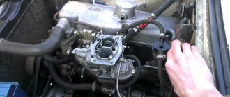
How to remove, install, replace a carburetor
For repairs and maintenance, the carburetor must be dismantled. To work, you will need a set of tools (pliers, open-end wrenches, screwdrivers) and a suitable room. Work is carried out on a cold engine. In short, first you need to disconnect everything connected to the carburetor, and only then remove it. The video below clearly shows the procedure for removing a VAZ 2107 carburetor.
Sequencing:
- Loosen the clamp on the corrugated pipe for the warm air intake, remove the pipe;
- Unscrew the air filter housing fasteners and remove it;
- Remove the suction cable: unscrew the bolt and screw that secure its shell, then loosen the cable itself;
- Remove the hose for removing crankcase gases from the fitting;
- Disable the idle economizer control: remove the wires from the microswitches;
- Disconnect the vacuum ignition timing regulator tube (remove it from the fitting);
- Pull the tube off the economizer;
- Remove the return spring;
- Loosen the clamps securing the fuel hoses, remove the hoses;
- Unscrew the 4 carburetor mounting nuts;
- Remove the carburetor from the studs.
Carburetor replacement is needed less frequently than repair. You can find any spare parts for this device on sale. After adjustment, cleaning and repair, the carburetor can be put back.
The carburetor is installed in the reverse order: first it is placed on the studs, then screwed to the body, and then all communications that were removed are connected to it.
How to clean a carburetor on the road
Sometimes it happens that the main jet in the carburetor gets clogged, if the carburetor in the classic is easy to clean, since the jet is easy to pull out, then in the VAZ 2108-2109 carburetor the jet is deep and can be pulled out for cleaning by removing the carburetor and turning it over. On the road this is of course a very long time.
There is an easy way to clean the VAZ 2108-09 carburetor jet without removing the carburetor, but you only need to remove the top part of the carburetor. In order to remove the jet from the carburetor you will need a toothpick or a finely planed stick.
To get to the jet, you need to remove the air filter pan, unscrew the bolt holding the choke cable (it is shown with an arrow in the photo below), disconnect the fuel hoses and the five bolts holding the top of the carburetor.
Next, unscrew the air jet, use a thin screwdriver to unscrew the main jet, stick a toothpick into it and pull out the jet.
After removing the jet from the carburetor, inspect the jet; there may be a speck in it; blow it out; blow it into the hole from which the jet was removed with a pump; if there is a speck in it, it will fly out into the carburetor's float chamber.
The carburetor float chamber can be drained of gasoline with a rag, then wiped well with the rag, removing debris, or blown out with a pump.
That's it, the main jet is cleaned, you can reassemble everything in the reverse order. This cleaning is easy to do on the road yourself, not to mention at home.
Sign of a clogged jet in the first chamber of the carburetor
The sign of a clogged first chamber of the carburetor is very simple: the engine runs fine at idle, but as soon as you lightly press the gas pedal, the engine stalls.
But there is a very similar sign that indicates a malfunction of the spark plugs or ignition coil; more often this sign appears in damp weather or heavy fog. You're driving a car, the engine starts to twitch, you give it gas and it accelerates, but as soon as you let off the gas the engine stalls, if you give it a little gas the engine doesn't react, if you press it into the floor or pull out the choke the engine starts to drag. It looks very much like the jet in the carburetor is clogged, but it’s not the jet, it’s the spark plugs that are failing. You can check this way: unscrew the spark plugs; if they are covered in dry black soot, then the spark plugs are to blame; if the spark plugs are very old with a lot of deposits, then such spark plugs need to be replaced or calcined on a gas stove.
Why does the VAZ engine stall at low speeds at 90c and not start?
There may be two reasons for this; the carburetor produces a very rich mixture. The rich mixture may be due to the carburetor needle (not holding the level), the float has a leak and has collected gasoline, the float level is incorrectly set, or the jets are incorrectly set to the calibers. While a cold engine needs a richer fuel mixture, which can be provided by an overflow carburetor, a hot engine needs a leaner fuel mixture, which is why the engine stalls when warming up.
The second reason is not related to the carburetor, but this is a sign that the ignition coil (bobbin) is faulty. Due to a malfunction of the ignition coil, a warm engine may also stall at low speeds and not start until it cools down.
Disassembling and cleaning the unit
Considering that the amount of impurities in our gasoline is simply off scale, cleaning the VAZ 2107 carburetor turns into a necessary procedure. It can be carried out without dismantling and disassembling, or it can be done with complete disassembly of the device.
Cleaning without dismantling, video.
Many car owners periodically treat the carburetor with special cleaning agents (carbocleaners). These aerosols do a good job of removing deposits in gaps, unless, of course, they are perennial “growths.”
- The engine must be turned off and cool before starting work;
- Remove the air filter housing;
- Using a wrench, unscrew the idle speed solenoid valve on the carburetor;
- Use a carb cleaner to treat the carburetor: external surfaces, jet channels (through a thin tube), chambers, air dampers, etc., as far as you can get;
- Leave for 10 minutes for the aerosol to dissolve deposits;
- Run the engine for a couple of minutes. A stream of gasoline will wash away the residue;
- If necessary, repeat the procedure, first waiting until the engine cools down.
If such cleaning does not produce results after twice use, the carburetor will have to be removed and cleaned “like an adult”, with disassembly.
Cleaning with removal, video.
How to remove the carburetor is already clear. Now the sequence of its disassembly:
- Remove the top cover by unscrewing the five mounting screws;
- Unscrew the jets and remove the emulsion tubes;
- Remove the accelerator pump nozzle - unscrew it, pry it off with a screwdriver and remove it;
- Remove the seal located under the valve;
- Remove the diffusers from the chambers using pliers or carefully knock them out with the handle of a screwdriver;
- Unscrew and remove the accelerator pump screw;
- Unscrew the adapter system nozzle holder and remove the nozzle itself;
- Unscrew and remove the idle fuel jet;
- Remove the accelerator pump cover: unscrew the 4 screws in the corners, remove the cover and the pump itself (diaphragm, pusher, spring);
- Remove the return spring from the pneumatic drive lever, then the rod clamp, after which remove the spring from the throttle valve drive lever;
- Remove the pneumatic drive by unscrewing the fasteners;
- Unscrew the 2 screws that secure the lower part of the carburetor to the body, remove the lower part; Remove the economizer and economizer microswitch with bracket;
- Unscrew the screws for adjusting the quantity and quality of the mixture.
This completes the disassembly of the carburetor. After this, you can start cleaning. The parts and body of the carburetor, including the jets, can be washed with kerosene, the seats of the jets and the jets themselves can be blown out with a compressor. It is advisable not to clean the jets with wire; it can damage the holes and then the jet will have to be replaced.
When the layers are washed off the metal, you can inspect it for corrosion, wear and defects. All parts that show signs of wear must be replaced with new ones. The carburetor is assembled in the reverse order, then adjustments are made and you can put it in place.
Lada Semerka
The appearance of the VAZ-2107 was complemented by some elements that were previously used on S-Class Mercedes. And this landmark was taken for a reason. Secretary General Leonid Brezhnev admired German cars and wanted the Union to have its own Mercedes. It was thanks to this brand that the characteristic protruding radiator grille appeared on the “Seven”. In combination with the new hood and design solutions applied to the front of the car, it looked harmonious. Rectangular optics also came in handy. The designers decided that it looks more solid and status than traditional round headlights. In addition, new bumpers (with hydraulic supports), power bars in the doors and tail lights appeared, in which the layout of the light blocks was changed.
A lot of work was done not only on the exterior of the “Seven”, but also on its interior. A modern instrument panel has appeared, a full-fledged instrument cluster (with a voltmeter, oil pressure gauge, tachometer), a new steering wheel, an upgraded heating and ventilation system, anatomical seats with integrated headrests, and much more.
The result was a truly beautiful car, completely in keeping with the spirit of the times. And most importantly, it fit the luxury class and was the most premium of all Zhigulis.
VAZ-2107 appeared in 1982. But work on the model was carried out for quite a long time. Back in 1978, the development appeared to the Chairman of the Council of Ministers of the USSR, Alexei Kosygin. And he already decided the fate of the model. He liked her. And only after this was a decree signed that the “seven” should go into production.
Tuning carburetor VAZ 2107, video
There is always room for tuning in a VAZ carburetor. To a certain extent, it really helps to improve the dynamic characteristics of the engine without interfering with the power unit. As a rule, tuning is done for the purpose of:
- reducing fuel consumption;
- improving engine power output;
- improved acceleration characteristics;
- delays in major repairs or engine tuning.
Carburetor modification and tuning, video.
- Replace diffuser No. 1 with a larger one, install fuel and air jets with non-standard ones, with greater capacity, replace the accelerator pump nozzle, remove the springs connecting the throttle valves to the vacuum pump and replace them with wires. All this is done to supply more fuel-air mixture;
- Replace the repair kit - a set of gaskets and consumables that quickly fail. Often, replacing the repair kit allows you to solve the problem with interruptions in the carburetor;
- Install a sports carburetor instead of the standard one. The sports version has better performance, which significantly improves engine dynamics. Of course, the old “Seven” will not turn into a Ferrari, but it will become a little faster. True, fuel consumption will increase, but this is not important for those who like to drive fast;
- Another step is to install a carburetor from another VAZ model with a more powerful engine. The principle is the same as with the tuning “sports” version - more performance, better dynamics;
- For those who understand, install another carburetor. Oddly enough, a pair of standard carburetors gives an increase in power (which is expected) and at the same time saves gasoline. Such tuning can be done by professional craftsmen who have the necessary equipment, but this is a really interesting option for improving the car.
Replacement of VAZ-2105 and VAZ-2106
By the mid-1970s, a crisis emerged at the Volzhsky enterprise. The fact is that all the models produced in Togliatti were in one way or another connected with the Italian “donor”. And not only the early “kopek” and “treshka”. Even the VAZ-2106 was unified with the Fiat 124 , although the model was positioned as its own development. Accordingly, the technical component and appearance of the Zhiguli were outdated. And something had to be done about this.
At that time, serious changes occurred in automobile fashion. Sharper shapes and right angles were now popular. Accordingly, the “six”, which appeared in 1976, initially looked outdated. And the management of the Volzhsky enterprise did not have to hope for the success of the model abroad.
It was then that a strategic decision was made - to cut ties with Fiat and do something of our own. The new model had to not only look modern, but also meet global requirements for exhaust gases, safety, and so on. In general, engineers and designers were required to take the product to a fundamentally different level.
In 1980, the VAZ-2105 . This car was very different from all other models of the Volga enterprise. It received a belt drive instead of a chain drive, a mounting block with relays and fuses appeared under the hood, single block headlights and massive tail lights appeared, and the seats were stuffed with polyurethane.
The model turned out to be successful and modern. But it lacked the polish to take a position in the “luxury” segment, where the “six” still ruled. And then the decision was made to create the “Seven” - an improved version of the “Five”.
Drift car VAZ-2107 16v Hater
This is a true “combat classic” from a series created in simple garage conditions. The car was clearly prepared for drift competitions by deep uprooting. Initially, a rather old specimen was taken, which it was not a pity to use for experiments. And a drift car is a constant process of modifications and adjustments, until the first serious accident. and again repair and remodeling.
The car is equipped with a VAZ 2112 Turbo td05 engine, additional remote oil radiators, a ZF 320 gearbox and many additional “tasty” grub things. In the end they changed the image to the “All Black” style with a flashy sticker on the side.
The Hungarian way to cross a VAZ-2107 and a Nissan with a turbo V6
Externally, it is almost factory stock, but a high-quality restored VAZ 2107 car in bright orange color. But having looked closely, or even better, listened to how its engine sounds, you understand that craftsmen from Hungary have done something special with our car
.
Opening the hood, you immediately understand that the creators, with great difficulty, but also with great skill, integrated the turbocharged 3.5-liter V6 VQ35DE engine from Nissan into the engine compartment. Its approximate power is now 450-500 hp.
However, for this it was necessary to significantly redraw the engine shield and transmission tunnel, manufacture a new exhaust system and many other technologically complex things.
Specifications
The success of the car was colossal. There were queues for the “Russian Mercedes”. At the same time, as for the technical part, the “seven” is not far behind the VAZ-2103. And under the hood there was the same archaic unit with a displacement of 1.5 liters and a power of 72 hp. Of course, it was modernized and equipped with a new, more economical and environmentally friendly carburetor.
The VAZ-2107 was also equipped with an engine from both the “five” (1.3-liter, 64 hp) and the “six” (1.6-liter, 75 hp). As for the gearbox, the car received both a 4-speed manual and a 5-speed.
The success of the G7 in the USSR influenced its prospects in other countries. The car was supplied not only to friendly countries, but to Western Europe. For example, two modifications of the Zhiguli were created for the UK market: VAZ-21077 (with a 1.3-liter engine) and VAZ-21078 (with a 1.6-liter engine). And the steering wheel of these versions, naturally, was on the right. In addition, export cars received changes in design and interior. But for the Chinese market, the “seven” (VAZ-2107-71) was equipped with a 1.4-liter engine producing 66 hp.
British prim limousine from. export VAZ 2107
In the 80-90s of the last century, VAZ classics were actively exported, and to the most bourgeois West. For example, the VAZ 2107 was supplied to the UK for some time under the name Lada Riva. And some Western tuning studios modified cheap Soviet cars at their own discretion.
Look at this unusual transformation of the export "Seven" into a real right-hand drive British limousine - or in English - Lada Riva Stretched Limousine. The lengthening work was done very well, with the rear doors recut and the roof raised to maintain proportions and the convenience of the VIPs being transported.
“Lucky seven” or VAZ 2107 - “a dream come true”
For Vladimir from Moscow, it all started with childhood memories of his father’s car. And he decided to make a kind of “action project” in the form of high-quality sophisticated sound tuning for the VAZ-2107.
The word “action” is key here to describe the modifications to the car in terms of sound, which included thorough audio preparation with vibration and noise insulation of the body and changes to the interior, installation of two new 115A generators, two Optima 55A gel batteries, 4 amplifiers, KICKER subwoofers, PEONEER speakers and ceiling monitor MYSTERI.
And the dynamic characteristics of the car are also determined by the 1.6-liter engine from the Chevy Niva, ready in future plans to install a GARETT GTX 28 turbine. The result is a unique dynamic multimedia exhibit, which has been winning various car audio competitions for 5 years. Just a dream! more in our article about this car
.
VAZ-2107 in modern Russia
After the collapse of the Soviet Union, the VAZ-2107 continued to maintain its leading position in sales. The appearance of the new front-wheel drive Lada family did not particularly affect it. The only thing is that after the debut of the “ninety-nine”, it ceased to be considered the most luxurious car. Since the country was “out”, and the market economy dictated its harsh conditions, the “seven” lost its luster. In order to survive, the company seriously saved on everything. And, first of all, on the interior finishing materials.
The VAZ-2107 quickly became just a car without any “zest”. Then there was also the unification of the wheels of all cars of the Volga enterprise. In the new millennium, the process of cost reduction and unification continued. First, the “seven” lost its trunk lid, which was replaced with a spare part from the “five.” Then the thresholds “lost” the rubber moldings.
Since the VAZ-2107 was still a good car, repairable and inexpensive to maintain, it began to be assembled in Ukraine (in Lutsk, Zaporozhye and Kremenchug). In Russia, geography has also changed. Syzran, Chechnya, and Udmurtia appeared. But in 2012, production of the “seven” was officially discontinued. Moreover, both in Russia and in Ukraine. But the model, as they say, did not give up without a fight. She managed to hold out for another two years at the plant in Cairo, where Lada Egypt was engaged in its production.
Lada Egypt
In 2014, the “seven” finally retired. True, the model still has not sunk into oblivion. And more or less living specimens continue to be found to this day. The VAZ-2107 lasted on the assembly line for more than thirty years. And during this time, over 3.1 million copies were released.
Vietnamese Rolls-Royce from VAZ-2107
In reviewing the most interesting tuning projects, one cannot do without truly freaky incarnations of the VAZ-2107. And the most surprising thing is that the ersatz parody of the famous luxury brand does not come from China, the birthplace of all kinds of counterfeits.
This VAZ-2107, stylized as a Rolls Royce, was made by a Vietnamese craftsman. Having bought a Soviet “Seven” for $500 and spending another $1,000 on modifications, the owner received an exclusive that passers-by and other road users cannot help but notice. And we will take this project as a little fun break before considering the next more serious work on tuning the “classics”.
VAZ-2107 as a “testing ground” from ClubTurbo Tuning Shop
To test and demonstrate their capabilities, the craftsmen from the ClubTurbo Tuning Shop company created this stunning car based on the “Seven”. It has everything: a spectacular, even slightly grotesque, appearance of a show car, and a modernized lowered suspension with fine tuning for street racing driving.
And most importantly, under the hood it has a new turbo engine of its own design by designers from ClubTurbo, running on liquefied natural gas, with an excess pressure of 0.8 bar, which is planned to be increased to 2 bar. And this is already quite an impressive figure!