Correctly set camber and toe angles are one of the key conditions for the normal operation of a car’s suspension. If these parameters deviate from the norm, a number of problems arise: uneven tire wear occurs, the vehicle’s handling and directional stability deteriorate, the steering wheel moves from the zero position when driving in a straight line. The load on shock absorber rods, silent blocks, CV joints, and steering system elements also increases.
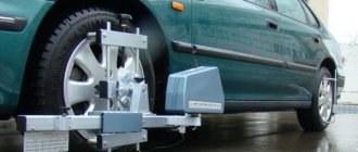
Measuring the toe-in and camber angles should be performed at certain intervals, on average 1-2 times a year. Checking the position of wheels in specialized car services is an expensive service, especially when using computer methods. Frequent visits to workshops are expensive, so many car owners are looking for ways to carry out such work in a garage. We invite you to familiarize yourself with a simple, but accurate and effective method for independently determining the alignment and camber parameters.
Advantages of the method
The technology discussed below is widely used by both beginners and experienced motorists. Among its main advantages it is worth highlighting the following:
- High accuracy. According to this criterion, this method is not inferior to the computer method. The technology makes it possible to measure almost all angular and linear indicators, which are determined using electronic equipment. Even the slope of the site on which the machine is located can be taken into account when measuring wheel alignment and camber.
- Body parameters are taken into account. With computer diagnostics, these characteristics are not determined by the equipment; at best, computer stands can calculate the clearance value. The method discussed in the article allows you to see the natural axis of symmetry of the body and determine the location of the chassis relative to it. This will help you understand why, after wheel alignment and camber adjustments, some wheels protrude from the arches more than others.
- Disc failure does not affect the results. The parameters of the wheel rims can be important when adjusting the angles on a computer. Therefore, some craftsmen working in specialized services refuse to carry out work if the car has wheels with different offsets on the front and rear axles. The method under consideration, in turn, makes it possible to measure alignment and camber, even if different disks are on the same axis.
When and why do you need it
Manufacturers recommend that owners of foreign cars carry out the procedure every 30,000 km, and owners of domestic cars - every 15,000 km. The period may be reduced if the car is operated in difficult conditions and often drives on bad roads. In some cases, an unscheduled procedure may be required:
- if the disc is crushed when entering a hole at high speed;
- if the chassis was repaired;
- if shortened springs were installed on the car or the ground clearance was changed for other reasons, auto buffers were installed;
- if when driving you clearly feel the car “pulling” to the side;
- if the tires begin to wear out much faster;
- if the steering wheel does not return well after negotiating a turn.
What will you get from the wheel alignment results?
- The directional stability of the car will improve. When driving in a straight line, the vehicle will move only forward, without moving to the side.
- The car will become more maneuverable, strong drifts will disappear, and control will be simplified.
- Fuel consumption will be reduced and tire service life will increase.
Depending on the purpose, one or another type of wheel camber can be selected
Important clarifications on the procedure for measuring wheel alignment angles
The proposed method only makes it possible to determine wheel alignment angles (AWA) in order to get an idea of the current wheel alignment and camber parameters. Further work on their adjustment can be carried out either with your own hands (if you have the appropriate experience and knowledge) or in a car repair shop.
It is assumed that the measurements are carried out with a working suspension and normal tire pressure. Therefore, the corresponding work related to the diagnosis and repair of the chassis is not considered.
It is also necessary to take into account that this article does not discuss what the toe-off and camber angles should be. We will only talk about the process of their measurements. The results obtained must then be compared with the factory values, which may differ for cars of different brands and models.
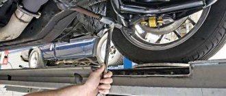
Before measuring the toe-in and camber angles, it is necessary to place the car on a flat, hard surface - for example, on the concrete floor of a garage. When driving onto a work site, keep the steering wheel in the zero position. In this case, the wheels will be as close as possible to the position in which they are when the car is moving on a straight road.
If the car is raised on a jack or lift after stopping, this will lead to unloading of the suspension, then the wheels will not be level enough on the floor. To eliminate such errors, you will need turntables or sliding platforms, which most car owners do not have. Therefore, it is strongly not recommended to lift the body before taking measurements. The car's suspension should be under the usual load.
Measurements should begin by determining the vanishing angles, since these are the parameters that are adjusted on most car models. This characteristic is determined for each of the four wheels, so it is sometimes called “semi-toe.” Individual toe-off is measured relative to the longitudinal axis of the vehicle. It can be built in several ways, let's look at it in more detail.
Deciding on the wording
Wheel camber indicator
The camber angle is the angle formed by the rotating plane of the wheel and its conventional vertical.
The value of this indicator determines what position the car’s wheels will be in when cornering, and, accordingly, how clearly the car will take the turn.
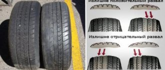
There are negative and positive values of this indicator: in the first case, the upper plane of the wheel is internal relative to the plane of its rotation, in the second case, it will be located on the outside.
Wheel alignment indicator
The wheel toe angle indicator is defined as the value between the vector of the direction of movement of the car (when viewed from above) and the plane in which the wheels rotate. This value will determine how controllable and stable the vehicle is on the road.
The inclination of the wheels “inward” of the car body (if we consider the projection of the car from above) is called positive toe, and outward - negative.
Custer
Another characteristic of the position of the car’s wheels is caster, which is the angle between the shock absorber in the MacPherson strut suspension and the inclination of the wheel knuckle.
. Caster is also defined as the inclined angle of the steering axis of the wheel. Drawing an analogy with the front wheel of a bicycle, this is the angle of the steering fork: the more the fork “lies”, the more the bicycle handlebar will tend to take a “straight” position.
Most car models are designed in such a way that the caster is 6 degrees and cannot be adjusted, so further we will only consider working with wheel alignment.
The importance of the correct position of the car wheels
Adjusting wheel alignment and camber is very important. A number of characteristics of the car will depend on how correctly the position of the car’s wheels is adjusted:
- the vehicle's resistance to skidding and overturning while driving;
- vehicle maneuverability and controllability;
- efficiency in terms of fuel consumption;
- car tire resource.
The position of the car wheels changes if:
- repair operations were performed that affected the suspension or steering system of the vehicle;
- the car on the road “caught” a hole, as a result of which the disk was deformed;
- the car received a strong blow;
- the car moved for a long time on an uneven road;
- the rods and steering tips have become unusable;
- the play of the longitudinal and transverse rods and the silent blocks of the levers has increased;
- the bridge is bent (in the case of models with a continuous bridge);
- the wheel bearing is worn out;
- the ball joint of the steering knuckle is faulty;
- The shock absorber support in the body cup is faulty.
Three options for constructing the longitudinal axis of a car
There are three different methods to choose from that can be used to create a “baseline” line when calculating individual wheel alignment angles:
- The longitudinal axis can be taken as a horizontal line that passes through the axis of symmetry of the body. It can be easily constructed by marking their midpoints on the front and rear bumpers.
- The second option is the longitudinal axis of the chassis. This line is lined up along points that are located at the centers of the distances between the wheel hubs.
- Quite often, the trust line is used as the longitudinal axis. It is laid strictly in the direction of movement of the rear axle of the car. This vector does not always coincide with the longitudinal lines built along the body or chassis, as in previous versions. A similar phenomenon is typical for cars in which the rear axle is turned slightly to the side. At the same time, the car drives sideways, which is often observed on old Zhiguli, Gazelles, etc.
Longitudinal axis and trust line on a car.
The angle between the “trast line” and the central longitudinal axis of the machine should ideally tend to zero. But in some cases, rear suspension defects cannot always be eliminated. Therefore, when diagnosing alignment and camber, measurements are taken based specifically on the “trast line”.
How to change castor - useful tips
Many specialists increase castor by several degrees. All this work can be done with your own hands; it will not cause difficulties even for renovation beginners. That is, the adjusting washers are removed from the elements and are located on the front suspension. As a result, the racks move slightly to the side, and thus, if there is a large caster angle, the more convenient it will be to turn the steering wheel when cornering. But there are advantages and disadvantages here.
How to change castor on a VAZ 2110
Advantages:
- The stability of the car at high speeds, and if the camber has not been done before, the car holds the road.
- Due to the fact that the angle between the wheel force and the rack axis when hitting a hole, the racks will not react.
- The front wheels will not touch the car's fenders; this is important for those who install low-profile tires on the car.
Disadvantages of this method:
- The steering wheel will be too heavy, to do this you need to unscrew the nuts on both sides of the hub, then unscrew the ball and screw on the lever.
- After this, the levers and braces are dismantled.
- And then remove a few washers, and then the suspension is reassembled in reverse order.
Any driver can perform wheel alignment on a VAZ 2110 with his own hands. But in order to take accurate measurements, you should use modern tools and equipment; specialists now use special stands. If you do not take measurements and set angles, and also carry out repairs incorrectly, you can end up in an emergency on the road. Also, the tires will wear out very quickly, which is why periodically check and do a wheel alignment on the car.
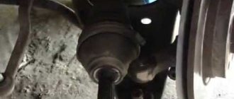
Measuring individual wheel alignment
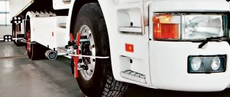
To measure the toe-in of each wheel, it is necessary to create a corridor consisting of two parallel lines. To create them, you can use strong threads, fishing elastic bands, and laser beams. The lines must run strictly horizontally; they must be aligned to the height of the wheel centers. A basic corridor can be created in three ways:
- The first is to attach the threads directly to the wheels. This is the simplest, but least accurate method. The wheels may have different offsets relative to the arches, which disrupts the parallelism of the lines.
- The second is fixing the threads on stationary supporting structures. The method is more accurate in comparison with the previous one, but it is inconvenient because during the process of adjustments and rolling the car, the chassis may shift relative to the constructed lines.
- The third is to create a corridor around the car body using rack and pinion fastenings. The slats are fixed in the front and rear of the car, strictly in the centers of the wheels.
There are many examples of such constructions on the English-language Internet. For example, type “BG rasing string lines kit” in the search.
The corridor around the car body is made of river fasteners.
In garage conditions, it is appropriate to use the most budget-friendly and simplest method. To measure alignment and camber, you will need two aluminum slats, which can be purchased at any hardware store. One of them needs to be placed on the floor near the rear or front axle of the car. Next, you need to make marks on the rack at a short distance from the wheels - about 5 cm. Then the distance between the marks is determined, the resulting value will be the width of the measuring corridor. By dividing this parameter in half, you can calculate the location of the midline. Next, you need to attach a second strip to the marked tube and transfer the resulting marks to it.
Setting marks on aluminum tubes.
Two additional marks are applied to the car’s bumper exactly in the center. They are set using a tape measure and marked with a piece of electrical tape or masking tape.
Installing a tag on a car bumper.
Aluminum tubes are fixed using ordinary office clothespins. They are attached to bumpers, mudguards or other body elements, depending on the design features of the car.
Fixing aluminum tubes on a car bumper.
Fixing aluminum tubes on a car bumper.
Next, you need to tighten rubber cords on the slats in the previously marked places, which can be purchased at any fishing store. Instead, you can use non-elastic threads, which can be secured to the tubes with rubber bands for money. This will avoid breaking the threads, ensure the necessary tension and minimize the error in determining the wheel toe angles.
Fastening rubber cords to aluminum tubes.
At the next stage, the measuring corridor is centered along the marks that were previously marked on the bumpers. Next, you need to set the steering wheel to the zero position; for greater accuracy, you can use a building level.
Setting the steering wheel to the zero position.
After the above steps, you can already detect the lateral displacement of the wheels. To do this, measure the distances from the centers of the hubs to the threads of the base corridor and determine the difference between them. This is relevant for drivers in whose cars the wheels extend out of the arches at different distances.
Measuring the distance from the centers of the hubs to the threads of the base corridor.
Now you can start measuring the individual alignment of each wheel. Measurements are carried out by determining the distances from the lines of the base corridor to the symmetrical points of the rim of the discs in front and behind the center of the wheel. The results obtained must be recorded in a notebook or, in the absence of one, written down with chalk on the asphalt in the garage.
Determination of distances from the lines of the base corridor to the symmetrical points of the rim of the disks.
Then you need to roll the car forward or backward half a revolution of the wheel without changing the position of the lines of the measuring corridor. It is important that the steering wheel remains in the same position. Next, you need to take repeated measurements of the individual wheel alignment several times. If there are no significant differences between two measurements, they can be accepted as true. If the difference is significant, you should roll the car a few tens of centimeters more and find “crooked” wheels. This way we calculate the wheel curves. To compensate for wheel runout during calculations, we find the most frequently repeated values of individual toe-in alignments.
To convert millimeters to degrees and minutes, we use the table below.
Table for converting millimeters of individual wheel toe into degrees and minutes.
When all half-toe angles have been determined with sufficient accuracy, the steering angle of the rear axle can be calculated. The presence of such an angle may be indicated by differences in the parameters of the semi-convergence of the rear wheels relative to the center line.
If adjustment of the rear wheels is not planned, you can reorient the base corridor along the trust line laid through the rear axle. To do this, you need to move the fixed slats so that the semi-convergence of the rear wheels is aligned with the new position of the corridor. Then you will need to adjust the position of the front wheels according to it, fixing the car’s steering wheel strictly in the center. Thus, the car will drive slightly sideways, but the driver will not notice it.
When determining the parameters of semi-toe-in, it is necessary to take into account the total toe-in of the wheels on the axles (on the front and rear axles), which consists of individual angles taking into account their signs. It is this indicator that determines whether the tires will wear out evenly and how controllable the car will be while driving. To find out the optimal value of overall toe for a specific car model, you should study reference materials that contain the manufacturer’s recommendations.
Adjustment
If the caster angle changes, self-locking nuts M12x1.25 will be needed. VAZ has a suitable article number - 16105011. If the angle is reduced, washers “2108-2904225” (part 24) are also needed. Installing one washer leads to a decrease in caster by 19 arc minutes.
Stretch (saber) and lever
To adjust any parameter, the wheel is hung up and removed. And when adjusting the caster, each of the two wheels is hung in turn. In general, the work ahead is long.
Caster angle
To add or remove washers, you need to remove the stretcher: use a flat 24 wrench to hold the stretcher itself, and use another wrench to unscrew the nut.
Removing suspension braces
Having unscrewed the nuts on both sides, the part cannot be removed immediately. You also need to unscrew the fastening of the lever to the stabilizer link (key “17”). To knock out the mounting pin, use an aluminum spacer.
The maximum number of washers is two in front and four in back (near the fist). Recommended tightening force – 43-52 N*m (stabilizer thrust), 160-176 N*m (stretch).
Camber angle
On all Tens, including the VAZ-2112, the camber is easily adjusted. The upper bolt, which holds the fist, is equipped with an eccentric. The nut on the bolt needs to be loosened and then rotated with a wrench - the camber angle will change.
Adjusting the right wheel camber
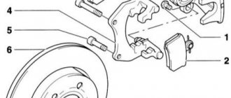
Mark the standard position of the adjusting screw head (Fig. 1). Loosen the nut on the bottom screw. The same must be done with the top screw - do not unscrew the nut completely! After completing the adjustment, tighten the fastener. You need two keys “19” (Fig. 2).
The recommended torque when tightening the nuts is 78-96 N*m.
Toe angle
The photo shows how the steering rod assembly with tips is arranged. The hexagon is designed for a 17mm wrench, but before you rotate it, you need to loosen the tightening screw on each of the ends - internal and external.
Steering rod and its ends
If you look at the arch from the outside, then by rotating the hexagon clockwise, we reduce the length of the tie rod. And vice versa.
When unscrewing the screw marked with an arrow in the photo, the tip “a” must be held. The same applies to the adjustment operation - the plane of the ball joint must remain parallel to the plane of the lever “b”.
External tip and swing arm
Anyone who ignores our advice will change the tips every other day.
Procedure:
- To adjust the right thrust, the steering wheel must be turned to the left;
- Taking the key “13”, loosen the two tightening screws;
Outer Tip Pinch Screw - Carry out the setup (you need a key “17”);
- Tighten the screw on the inner and then on the outer steering tip.
The tightening force for the coupling screws is 27-33 N*m.
Measuring camber angles
To determine these parameters, the base corridor is not needed; it can be removed. Camber angles can be determined in several ways: using a plumb line, bubble level, digital inclinometer or other inclinometer.
Before you start measuring camber angles, you need to make sure that the car is standing on a level surface. If the camber is measured using a digital inclinometer, then it is enough to calibrate the device by the slope of the surface on which the car is located. To do this, apply a square to the surface and check the position of the protractor with the position of its vertical edge.
Place two vertical marks on the wheel rim with a marker or chalk. We apply the cord with a plumb line to the wing, and along the marks with a ruler or caliper we measure the distance from the rim to the cord at the top mark, and then at the bottom. The difference should be within +-2mm. We roll the car a quarter turn of the wheel (90 degrees) and make two more vertical marks. Again we measure the distance from the plumb line to the wheel rim, thereby leveling out the measurement error associated with the runout of the wheel disk.
Determination of the camber angle.
For front-wheel drive vehicles, the average values of camber angles are considered to be 0 ± 1 mm; for rear-wheel drive vehicles, the normal range is +1 ± 3 mm. For wheels of sizes 13 and 14 inches, 1 millimeter of camber is equal to approximately 10 minutes of arc. It is best to find out the exact wheel camber tolerance for a specific car from the recommendations of the car manufacturer.
Measuring the camber angle using a bubble level.
The camber angle can also be measured using a bubble level or a phone with an angle measuring program installed.
Wheel alignment of VAZ Lada 2112 in auto repair shops in Moscow
15 car repair companies
- Afto-service
- st. Polikarpova, 27, building 3
- +7 (495) 99… show all
- The site of the company
- Stomobil
- Lr-technik
- Comandante
- Tiger box
- London-auto
- Dvs
- RF-motors
- Autoelite service
- Gag-auto
- Apollo Motors
- Apollo Motors
Popular companies
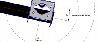
Measuring the longitudinal and transverse angle of inclination of the axis of rotation
Of greatest interest is the measurement of the tilt parameters of the rotary axes. Their position is determined by two key characteristics: lateral inclination and longitudinal (caster).
A short video (2 min) about what a caster is
If the wheels of a car could turn 90 degrees and stand across the body, these parameters could be easily calculated using an inclinometer. But in real conditions this is impossible to do, so you need to limit yourself to a rotation of 20 degrees in both directions relative to the zero position. The difference in the obtained angles must be multiplied by an additional factor of 1.5 - this is necessary to compensate for errors that are allowed during the measurement process.
To measure caster, the bubble level bulb must be mounted perpendicular to the plane of the wheel.
To determine caster, you first need to turn each wheel 20 degrees in front of the steering axis: right to left, and left to right. In this case, you need to set the inclinometer to zero or write down the results. Next, the wheels are turned behind the turning axis: right to the right, left to the left. If the angle measured behind the steering axis is greater than the angle measured in front of the steering axis, then the caster is positive. If it's the other way around, then the caster is negative. The protractor should show a slight difference of a few degrees. This difference should be multiplied by the same factor of 1.5. For example, if the protractor showed a value of +2 degrees, then the caster value should be taken as +3 degrees.
The transverse inclination is calculated in a similar way, but the protractor is installed in a slightly different position. For additional convenience, you can use a smartphone, on which you should install in advance an application that simulates two mutually perpendicular bubble levels. An ordinary building level, preferably with a rotating bubble, will also work for these purposes.
To measure the lateral inclination of the steering axis, the bubble level flask must be fixed parallel to the plane of the wheel.
Measuring the level of lateral inclination of the axis of rotation.
If the task is not to measure specific numerical values of slopes, but only to compare them (they are not adjustable on most cars anyway), then the results do not need to be multiplied by a correction factor of 1.5. The main thing is to make sure that the angles are equal on both axes (right and left).
In the process of self-measurements, it is not necessary to strictly observe the rotation of the wheels exactly 20 degrees, especially when there are no appropriate tools to determine these angles (for example, graduated turntables). You can turn the steering wheel about 3/4 of a turn. It is necessary to ensure that when turning left and right, the steering wheel is locked in symmetrical positions. To do this, you can put some marks on the bottom of the steering wheel. When the steering wheel is in zero position, the line connecting the marks must run strictly horizontally.
Another way to get accurate results is to draw corners on the asphalt near the wheels using a protractor. If you don't have this tool, you can use a square sheet of paper with equal sides. Folding it diagonally, we get an angle of 45 degrees. Then one corner is folded in half again, resulting in an angle of about 22.5 degrees, which is close to the standard 20. Next, you need to attach the sheet to the wheel and outline its edge with chalk, thereby creating the necessary marks on the asphalt.
Marking the corners for turning the wheel
What should the installation angles be: negative and positive values?
The optimal value for a passenger car is either zero or slightly negative (i.e., the wheels should point slightly outward with their bottoms).
Positive values can be set from 0 to 4.5 degrees. Sports cars use a negative value of -0.5 to -5.5 degrees. Thanks to this, a high level of grip is achieved and cornering stability is increased.
Negative angles have disadvantages. So, when driving in a straight line, the inner edge of the tire will wear out faster, and instability may occur during acceleration and braking on a straight path. The best option is to set the indicator at -0.5 degrees.
Positive and negative camber.
Making wheel alignment for a VAZ-2110: theory and practice with your own hands
Many car enthusiasts remember the immemorial times of the Soviet Union, when many vehicle owners made wheel alignment on their Zhiguli using a thread. If this technology was already available then, then purely theoretically, this operation could be done with your own hands on any car.
The video will tell you how to independently adjust the wheel alignment angle, what tools and knowledge you will need, and also talks about the subtleties and nuances of the procedure.
Why does the brake pedal hit when braking?
Why does the brake pedal squeal when you press the brake? Most often, when various malfunctions are detected, motorists turn to a specialized service.
Do-it-yourself windshield polishing? See here for detailed instructions.
Do-it-yourself ignition switch illumination, more details in our article.
Do you need to replace your front suspension springs? You will find details in this article.
Yes, this is a common cause of “impacts” on the steering wheel or brake pedal, but there are still other malfunctions that give such a result. Let's consider what main malfunctions can cause such behavior of the car when the speed decreases.
- The first reason, which we have already described above, is deformation of the brake disc. Most often this happens due to severe overheating. The average operating temperature of a modern brake disc is 200-300 degrees. Overheated soft metal is prone to deformation, which causes irregularities to appear on the surface of the disk, which cause shocks. This problem can be solved by replacing the disks. If your driving style is quite aggressive, then you should consider purchasing brake discs that are more temperature-resistant. The ventilation of the disks, as well as their area, is responsible for heat resistance; the larger it is, the better the heat transfer.
- Wear of brake discs. With severe and uneven wear, scuffing may appear on the braking surface of the “pancake”, which will cause runout. Just a replacement solution. If the discs on one axle have uneven wear, it means that the braking of the right and left wheels occurs unevenly, which can also complicate driving and become a threat to life.
- Overheating of Ferodo coating on the pads. When the brake surface of the pads overheats, the friction linings simply begin to crumble, which is why they cannot properly and evenly press the brake disc and stop the wheel.
- Uneven or severe pad wear. Just like the surface of the disc, the braking surface of ferodo pads wears out over time. Wear may occur unevenly, which will affect the wear of the disc and the process of stopping the rotation of the wheel. Everything can be solved with a simple replacement. If the brake discs still have a sufficient layer of working surface and there are no defects, then you can only get by by replacing the pads as a pair on the axle. When installing new pads, be sure to clean the bracket, otherwise this may lead to the pad becoming sour over time. The pad must have free play in the bracket so that the caliper correctly presses its entire surface against the brake disc.
- Inoperative brake caliper cylinders. Another common problem is stuck pistons. This often happens due to torn boots of the brake pistons; because of this, dirt and moisture get into the brake cylinder, which “kills” the lubrication of the mechanism, which over time leads to souring and inoperability of the entire device. A caliper repair kit will help solve this problem. The kit will include a new boot, brake piston and lubricant. Everything is simple, you just need to “squeeze” the old piston out of the cylinder by pressing the brake pedal, then we clean everything, lubricate the cylinder walls, the piston and press it back, and install a new boot.
- Worn rear brake pads. Often noticeable only during heavy braking. Usually, in moderate driving mode, only the front mechanisms are involved in the braking process, the rear mechanisms are connected either later or during sharp braking. So if the beating does not occur with pressing the pedal, but later or towards the end, then this is most likely due to worn rear brake pads.
- Rear brake drums are worn or bent. When braking, the drum presses the pad unevenly or inconsistently, so there is no full contact between the pad and the braking surface, braking efficiency decreases and vibration is transmitted to the pedal or body. The reason for wear of these parts is most often their age, and the solution to this issue is simple - replacing worn out consumables with new ones.
- Severe wear on wheel bearings. Due to play and wear of the bearing working surface, vibration and hum are transmitted to the wheel. When braking, the front suspension of the car is loaded, which creates vibration from the bearing. It is possible to check bearing wear on a lift by checking the wheel for vertical play; if there is any, then the bearing has already “outlived” its usefulness and needs to be replaced.
Opinion of car owners about wheel runout when driving
- The steering knuckle and hub need to be replaced.
“The problem is solved by replacing the steering knuckle with the hub; it is better to choose a contract one as a new one. There are no other reasons for knocking.” - Perhaps the problem is a poorly pressed bearing.
“Most likely, the front wheel hits when driving due to uneven pressing of the bearing. Its seat may also be severely worn. The hub allows up to five bearing replacements. However, its sloppy fit is enough to cause beating. But the shaft itself is very difficult to deform, because it is large in diameter and short. It’s impossible to bend it.” - The reason is dirt between the discs.
“You hang up the front of the car and remove the wheel. Then you spin the hub with the engine. If the brake disc beats, you also remove it. Spin the hub again. If there are beats, it needs to be replaced.I will assume that, most likely, inept hands or contamination between the disc and the hub are to blame.
Therefore, the first step is to remove the wheel and brake disc. Next, we clean all contact points with a brush. If these measures were not enough, we return to the previous post.”
- The disk on the hub did not sit tightly, hence the vibration.
“I’ve come across stamped disks where the seat for the hub was made by stamping under a press. As a result, a technological bead was observed at the edges. Because of this, the disc did not fit tightly to the hub and moved while tightening the bolts. When driving there was a beating and very strong vibration. This disk was balanced on the bench, but as soon as it was turned on the axis of the machine, the procedure had to be started all over again.A good solution in this case would be to examine the wheel and tire for runout using an indicator stand.”
Tire aging
Even though rubber typically wears out before it reaches its expiration date, there are certain deadlines. Aging rubber can cause it to wear unevenly and severely. It is also worth noting that improper storage can lead to rapid aging of rubber.
All manufacturers indicate how long a product can last under certain operating conditions. It also indicates how it should be stored.
Aging of rubber leads to the fact that it loses its tightness and the structure becomes porous. After some time, moisture begins to penetrate deep into the structure. As a rule, manufacturers use metal cord to strengthen the structure. Moisture leads to the destruction of the metal base. According to accepted standards, a tire cannot be used after 10 years from the date of its manufacture.
More about the block
- Coolant level;
- Washer fluid level;
- Oil level in the crankcase;
- Indicator of non-working lamp;
- Brake pad wear indicator;
- Seat belt indicator;
- Indicator of the front left door not closed;
- Indicator of the front right door not closed;
- Indicator of the rear left door not closed;
- Indicator of the rear right door not closed;
Open doors
This function works thanks to limit switches in the door. When the door is opened, the switch contacts close and the door open lamp lights up. Each limit switch is responsible for the door in which it is installed.
Quite often it happens that due to oxidation of the limit switch contacts, the indication does not operate. This problem is solved by removing the end switch and cleaning its contacts with sandpaper.
Low oil level
A special oil level sensor is installed in the engine crankcase, which informs the driver when the level drops to a minimum value. The sensor is a reed switch with a float; the contacts of the reed switch close when the oil level drops, which leads to the lighting of the corresponding lamp on the display unit.
Low antifreeze level
This indication system is similar to the oil level design. A sensor is installed in the expansion tank, operating on the principle of an oil level sensor. When the coolant level decreases, the contacts on the sensor close and the low antifreeze level indicator lamp lights up.
Low washer fluid level
The principle of operation of this indicator is to measure the windshield washer fluid level. There is a level sensor in the washer reservoir, the same as in the expansion tank. It measures the level and, when the minimum mark is reached, lights the lamp on the display unit.
Front pad wear
This indication informs the driver about the wear of the front pads; this occurs using a sensor that is connected to the pad itself.
It is important to note that in order for this indication to work, it is necessary to use special blocks in which this sensor is built
Unfastened seat belt
This function has long been known on cars of foreign origin, but it was used for the first time in AvtoVAZ. The sensor built into the seat belt buckle closes its contacts when the belt clip is inserted into it. If you start driving without a seat belt fastened, the display unit will begin to emit a sound warning of danger.
Burnt out lamp indication
The essence of this function is to inform the driver about one of the burnt-out lamps in the headlights or taillights. This function works by measuring the resistance in the power supply circuit of headlights or flashlights. As soon as the lamp burns out, the power circuit is interrupted, which causes the indicator on the unit to light up.
Forgotten key in the ignition
After stopping the engine and turning off the ignition, if you open the door while the key is inserted into the lock, the display unit will emit a sound signal that will last 10 seconds and will stop if you close the door again or remove the key from the lock.