All modern cars are equipped with ABS sensors that include Brake Assist Control. This is one of the delicate systems that often fails on budget machines. In Europe, for several years now, manufacturers have been required to equip any production cars with this safety system, and manufacturers of cheap cars are clearly saving on high-quality ABS by installing systems that are not very durable and practical. Sensors of this system are installed on all four wheels, they are activated when sudden braking occurs and a wheel locks. In this case, the system unlocks the wheel, allows it to turn and gradually slows down.
In fact, it turns out that cheap ABS not only does not help to brake more effectively, but also lengthens the braking distance. There is another serious problem - after several years of operation, when the car is out of warranty, on many cars the ABS light comes on for no reason. Firstly, it is inconvenient to drive with a light constantly on on the dashboard, and secondly, if you have a clear impression that something is wrong with the car. Interestingly, a lit ABS light does not always mean a problem with the anti-lock braking system. There may be other problems.
Why does the ABS light even come on?
In a normally running vehicle, this indicator shows you that the wheels have been unlocked. In this case, everything works fine, the sensors sensed the need to turn on the safety system, initiated its operation and demonstrated to the driver that some assistance was provided when braking. When you see the ABS light on while braking, it is better to release the brake pedal a little and take over control of the car. If you have an expensive, high-tech car, you can trust the well-thought-out systems and let ABS+EBD do the job. In other cases, the light may be on for the following reasons:
- the sensors are clogged, the on-board computer indicates that the diagnostic error code should be read;
- Dirt or rust got on the sensors, which caused the anti-lock braking system to turn on incorrectly;
- there is a problem in the on-board electrical system, which is demonstrated by random lights coming on;
- the wheel bearing has failed, which forces the sensors to constantly turn on the anti-lock braking system by mistake;
- the fuses in the unit responsible for the ABS system have failed and are passing the signal directly;
- There was an error in the computer that caused the ABS light to come on.
Also, sometimes troubles occur with the generator and other elements of the machine’s electrical circuit, which can result in the lighting of the diagnostic system light or warning lights of any type. For example, on a Volkswagen car produced in the 2000s, the anti-lock braking system light comes on even if there is an error in completely different components. Therefore, self-diagnosis is only a partially acceptable method of solving the problem, because often the driver does not have special tools at hand for a good investigation.
Main types
The ABS sensor is considered the primary measuring part of the anti-lock braking system.
The device consists of:
- A meter placed permanently near the wheel;
- An induction ring (rotation indicator, impulse rotor) installed on a wheel (hub, wheel bearing, CV joint).
The sensors are available in two versions:
- Straight (end) cylindrical shape (rod) with a pulse element at one end and a connector at the other;
- Angled with a connector on the side and a metal or plastic bracket with a hole for a mounting bolt.
Two types of sensors are available:
- Passive - inductive;
- Active - magnetoresistive and based on a Hall element.
ABS allows you to maintain controllability and significantly increase stability during emergency braking
Passive
They are distinguished by a simple operating system, but are quite reliable and have a long validity period. Does not require a power connection. An inductive sensor is essentially an induction coil made of copper wire, in the middle of which there is a stationary magnet with a metal core.
The meter is located with the core to the pulse rotor in the form of a wheel with teeth. There is a certain gap between them. The rotor teeth are rectangular in shape. The opening between them is equal to or slightly larger than the width of the tooth.
While the vehicle is in motion as the rotor teeth pass near the core, the magnetic field penetrating the coil is constantly changing, forming an alternating current in the coil. The frequency and amplitude of the current are directly dependent on the speed of the wheel. Based on processing of this data, the control unit issues a command to the magnetic valves.
Article on the topic: How to check the fuel pump relay yourself
The disadvantages of passive sensors are:
- Relatively large dimensions;
- Poor accuracy of readings;
- They begin to function when the car picks up speed over 5 km/h;
- Triggered by minimal wheel rotation.
Due to frequent errors, they are installed extremely rarely on modern cars.
Magnetoresistive
The work is based on the property of ferromagnetic materials to change electrical resistance when exposed to a constant magnetic field.
The part of the sensor that controls changes is made of two or four layers of iron-nickel plates with conductors applied to them. Part of the element is installed in an integrated circuit that reads changes in resistance and generates a control signal.
The impulse rotor, which is a magnetized plastic ring in places, is rigidly fixed to the wheel hub. During operation, the magnetized sections of the rotor change the environment in the plates of the sensitive element, which is recorded by the circuit. Its output produces pulsed digital signals that enter the control unit.
This type of device controls the speed, direction of rotation of the wheels and the moment they come to a complete stop.
Magnetoresistive sensors record changes in the rotation of vehicle wheels with great accuracy, increasing the efficiency of safety systems.
Based on Hall element
This type of ABS sensor operates based on the Hall effect. In a flat conductor placed in a magnetic field, a transverse potential difference is formed.
Hall effect - the appearance of a transverse potential difference when a conductor with direct current is placed in a magnetic field
This conductor is a square-shaped metal plate placed in a microcircuit that includes a Hall integrated circuit and a control electronic system. The sensor is located on the opposite side of the pulse rotor and has the form of a metal wheel with teeth or a plastic ring, magnetized in places, rigidly fixed to the wheel hub.
The Hall circuit continuously produces signal bursts of a certain frequency. At rest, the signal frequency is reduced to a minimum or dies out completely. During movement, magnetized areas or rotor teeth passing by the sensing element cause changes in the current in the sensor, which are recorded by the tracking circuit. Based on the received data, an output signal is generated and sent to the control unit.
Sensors of this type measure speed from the beginning of the vehicle’s movement and are distinguished by the accuracy of measurements and the reliability of their functions.
What can you check yourself if the ABS light comes on?
The first thing you can do on your own in such a situation is to go to a car wash and ask for a good wash of the rims. Often, this intensive pressure washing can clean the ABS sensors located near the brake discs. On your way to the car wash, you can perform another simple test. Accelerate to a speed of 80-90 kilometers per hour, close the windows and turn off the music. If in this driving mode you hear a slight or annoying hum in the area of the wheels (front or rear), the likely cause of the light is a failure of the wheel bearing. There are several other things you can do:
- inspect the fuse box and replace the module that is responsible for the operation of the anti-lock braking system;
- if possible, read the diagnostic error code and read about it on the forums;
- to a specialist, describing your situation, and then try to correct the error yourself;
- get to the ABS sensors yourself by jacking up the car and removing the wheels to check their cleanliness;
- inspect the electronic control unit located under the hood, check that there is no liquid in it or on it;
- the best solution is to go to a service station and pay for diagnostics of the car’s anti-lock braking and electrical systems.
Checking the quality of work performed
After replacing the sensor, its functionality is checked. To do this, it is enough to accelerate to a speed of 40 km/h on a flat, safe section of the road and perform sharp braking. If the car stops without pulling to the side, vibration is transmitted to the pedal and a specific sound of brake pads being activated is heard - the ABS system is operating normally.
Today you can easily find and buy any ABS sensors - from expensive original devices to analog parts at an affordable price. Remember that proper selection of system elements plays an important role in its uninterrupted operation. When choosing a sensor, study the manufacturer's instructions and make sure that it fits the car, and this review will help you replace the device yourself.
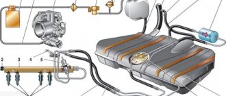
I purchased a controller for DRLs with the ability to control it from a speed sensor. The manufacturer has a description of the installation with a pulse sensor from the box. Only cars with ABS.
What can you come up with to remove the signal from the wheel sensor?
Please explain how this ABS sensor works? Is it possible to test the health of the sensor with an LED?
- Incorrect speedometer readings on VAZ Largus - 3 answers
- Where is the speed sensor located and how to change it, Lada Largus? – 1 answer
- Is it possible to disconnect the speed sensor in Lada Largus? – 0 replies
If you are interested in the operation of the sensor itself, then briefly it looks like this.
The sensor is an inductive sensor that contains a generator - it refers to three wire sensors (inductive and Hall sensors, that is, active). When the sensor is located near a gear wheel, at the moment when a tooth appears next to the coil, the generation is disrupted. This disruption is converted by the electronic circuit into a rectangular pulse at the output.
If we consider the work further, the ABS system converts these impulses into wheel rotation speed, compares the rotation speeds and adjusts the braking forces without allowing the wheels to lock. Naturally, the algorithm of the system’s operation is much more complicated, but for a general understanding of the work, it makes no sense to delve into these jungles.
Front wheel speed sensor
This is what the sensor looks like in the hub assembly (steering knuckle): 1 – speed sensor mounting ring; 2 – inner ring of the front hub bearing; 3 – front wheel speed sensor; 4 – wheel hub; 5 – steering knuckle
Wheel bearing with sensor: 1 – magnetic bearing washer; 2 – speed sensor; 3 – hub bearing; 4 – speed sensor mounting ring
Jack up the car and place it on reliable stands, or place it on a two-post lift, apply the parking brake and turn off the ignition.
Remove the front wheel.
(Raise the car to a height convenient for performing work).
1 — bracket for fastening the speed sensor wiring harness; 2 — fender liner clamp; 3 — front wheel arch liner; 4 — front wheel speed sensor; 5 — bracket for fastening the speed sensor wiring harness on the front suspension strut; 6 - steering knuckle
Remove fastener 2, Figure 21-2, front wheel arch liner in the area where the speed sensor wiring harness is located (flat-head screwdriver).
Note: For ease of operation, you can remove the front fender liner (see here)
Remove the speed sensor wiring harness from the grooves in bracket 5 of the front suspension strut and from holder 1 on the mudguard of the engine compartment.
Remove insulating foam 1, Figure 21-3, from the knuckle speed sensor mounting socket (optional).
Figure 21-3 — Removing the front wheel speed sensor:
1 - insulating foam; 2 — front wheel speed sensor; 3 - latch
Remove speed sensor 2 from the mounting hole on the steering knuckle by using a screwdriver to press out the locking tab of sensor 3 (flat screwdriver).
Disconnect the speed sensor wiring harness connector from the front wiring harness and remove the sensor.
Attention. The wheel speed sensor insulating foam must be replaced.
Install insulating foam into the speed sensor mounting slot on the steering knuckle.
Connect the speed sensor wiring harness connector to the wiring harness
Install the speed sensor into the mounting hole on the steering knuckle until the latch engages.
Install the speed sensor wiring harness into the grooves of the front suspension strut bracket and into the holder on the mudguard of the engine compartment.
Secure the front wheel arch liner with the clamp.
ABS turns on randomly, the light blinks or lights up periodically
One of the most difficult forms of breakdowns is the constant blinking of the ABS light bulb. This means that the anti-lock braking system sensors send incorrect signals to the computer, which, in turn, issues other incorrect commands to the vehicle's systems and modules. In such cases, many people prefer to simply turn off the anti-lock system, since unpleasant incidents may occur. For example, turning on ABS at a speed of 90 kilometers per hour with light braking can damage the chassis of the car and contribute to a complete loss of control over control. It's better to do this:
- bring the car to a service center for diagnostics, find out the reason for the chaotic operation of the equipment;
- for domestic cars equipped with a primitive anti-blocking device, it is better to immediately disable the system;
- complex designs and on-board electronic systems of foreign cars will have to be reflashed for repair;
- on some machines it will be easier to find the problem and fix it than to disable the anti-lock;
- you need to keep in mind that this particular system is not always the cause of the ABS light coming on; the problems can be different;
- During the diagnostic process, it is better to check the entire on-board electrical system and equipment.
By paying a certain amount for a car inspection, you can get the right answers to important questions. Sometimes a light that comes on on the panel can develop into a full-fledged repair of important units and components of the car, so you will have to spend a lot. But in most cases, this problem is not so expensive to solve. The cost of repair work depends, of course, on the make and model of the car, and on the price of spare parts. If an ABS sensor for a domestic car costs from 600 rubles, then a Japanese SUV will cost more than 10,000 rubles to replace one such sensor. We suggest watching a video about solving a similar problem using computer diagnostics:
[No flooding] Anti-lock brake system Kalina and Priora
ANTI-LOCK BRAKE SYSTEM FOR CAR FAMILIES LADA KALINA AND LADA PRIORA – DEVICE, DIAGNOSTICS, REMOVAL AND INSTALLATION OF MAIN UNITS
Carry out work in accordance with the requirements of the “Inter-industry rules for labor protection in road transport” POT RM-027-2003 and the labor protection instructions for mechanics in force at the enterprise. ATTENTION. When dismantling the hydraulic unit and pipelines, take measures to prevent brake fluid from spilling. 1 General description of the system, features of the design and operation The anti-lock braking system (ABS) is part of the working brake system of a car and is designed to automatically regulate the degree of wheel slip in the direction of their rotation during braking by changing the brake fluid pressure in the working brake cylinders in order to prevent loss controllability and stability of the vehicle and increase braking efficiency. ABS also performs the functions of distributing braking forces along the axes of the vehicle and distributing braking forces along the sides of the vehicle when braking in a turn. ABS consists of the following main components: — hydraulic unit (part 11180-3538010-00); — two front wheel speed sensors (part 11180-3538350-00); — two rear wheel speed sensors (part 11180-3538370-00); — two front wheel rotors (part 11180-3538390-00). The front wheel rotor is part of the outer joint (part 11186-2215012-00); — two rear wheel rotors (part 11180-3538400-00). The hydraulic unit (HA) structurally consists of an electronic control unit (ECU) and a hydraulic modulator containing electromagnetic valves (EMV), a return pump and a return pump electric motor (ERM). Wheel speed sensors (DSS) generate signals about the speed of each wheel of the vehicle, which are transmitted to the electronic control unit of the hydraulic unit. The operation of wheel sensors is based on the principle of electromagnetic induction. When the wheel rotates, the teeth and cavities of a special rotor pass past the sensor and induce an electrical signal in the sensor winding, the frequency of which is proportional to the angular speed of the wheel and the number of teeth on the rotor. The electronic control unit logically processes wheel speed signals and, depending on their condition (excessive acceleration or deceleration of the wheel), sends control commands to the hydraulic modulator.
Figure 1 — Schematic diagram of the ABS of cars of the LADA KALINA, LADA PRIORA families: K1 – front harness block to the hydraulic unit; K2 – hydraulic unit connector; PL – front left; PP – front right; ZL – rear left; ZP – rear right; VP – inlet; VYP - graduation
Based on received commands, the hydraulic modulator, by turning on or off the solenoid valves, reduces, increases or maintains constant the pressure of the brake fluid in the wheel brake cylinders, thereby ensuring optimal control of the braking forces. When the pressure decreases, excess brake fluid is pumped by the return pump into the master cylinder.
3 Diagnostics The ABS condition is monitored by diagnostic indicators (orange ABS and EBD symbols) located in the instrument cluster, which, after turning on the ignition, should turn on for 3 seconds and turn off. If a malfunction occurs in the ABS, the electronic control unit of the hydraulic unit turns on the corresponding diagnostic indicator. To view fault codes and ABS parameters, the software and hardware complex “AS: Diagnostics” is used. The list of ABS fault codes displayed by the diagnostic tool is given in Table 2. Table 2 Code Description of code C0035 Failure in the front left DSC circuit or unreliable signal C0040 Failure in the front right DSC circuit or unreliable signal C0045 Failure in the rear left DSC circuit or unreliable signal C0050 Failure in the rear right DSC circuit or unreliable signal C0060 Failure in the front left exhaust circuit EMC C0065 Failure in the front left intake circuit EMC C0070 Failure in the front right exhaust circuit C0075 Failure in the front right intake circuit EMC C0080 Failure in the rear left exhaust circuit C0085 Failure in the intake rear left EMC circuit C0090 Failure in the exhaust rear right EMC circuit C0095 Failure in the intake rear right EMC circuit C0110 Failure in the EVN circuit C0121 Failure in the relay circuit for turning on the supply voltage of the EMC C0161 Failure in the brake signal switch circuit C0245 Error in measuring the DSC frequency C0550 Internal computer malfunction C0800 Supply voltage is below or above the operating range
3.1 If fault codes C0035, C0040, C0045 and C0050 are detected, check the electrical circuits to the corresponding DSC for open and short circuits, check the supply voltage of the corresponding DSC (U supply DSC ? 0.8 U supply ECU). 3.2 If fault code C0110 is detected, check the supply voltage at contact 2 of the harness block to the hydraulic unit. 3.3 If fault code C0121 is detected, check the supply voltage at contact 3 of the harness block to the hydraulic unit. 3.4 If fault code C0161 is detected, check the electrical circuit to the brake light switch for open and short circuit. At contact 20 of the harness block to the hydraulic unit there should be: - low-level input voltage no more than 0.3 U power; — high-level input voltage of at least 0.8 U supply. 3.5 If fault code C0245 is detected, check the reliability of the DSC fastening and the gaps between the DSC and the rotor. The gap between the front wheel speed sensor and the front wheel rotor teeth should be (0.45-1.55) mm (set of feeler gauges). The gap between the rear wheel speed sensor and the rear wheel rotor should be (0.2-2.3) mm (set of feeler gauges). 3.6 If fault code C0800 is detected, check the supply voltage at contact 18 of the harness block to the hydraulic unit. It should be within (10-16) V. 3.7 If fault codes C0060, C0065, C0070, C0075, C0080, C0085, C0090, C0095, C0550 are detected, replace the hydraulic unit.
4. Hydraulic unit of the anti-lock brake system - removal and installation Removal: - place the car on a two-post lift, apply the parking brake and turn off the ignition (electrohydraulic lift type P3-T-SP with a lifting capacity of 3 tons); — disconnect the plug block of the front wiring harness from the hydraulic unit; — disconnect the brake pipes going to the brake mechanisms from the hydraulic unit of the anti-lock brake system. Install plugs in the holes of the hydraulic unit and on the brake pipes (wrenches type 41 08 11 13 f. “Stahlwille”, 256 11/13 f. “USAG” for brake pipe fittings, technological plugs); — disconnect the pipe of the primary and secondary circuits of the main brake cylinder from the hydraulic unit of the anti-lock braking system. Install plugs in the hole of the hydraulic unit and on the brake pipe (wrenches type 41 08 11 13 f. “Stahlwille”, 256 11/13 f. “USAG” for brake pipe fittings, technological plugs); — for cars of the LADA PRIORA family, unscrew the three nuts securing the hydraulic unit bracket to the front left side member (replaceable head 13, wrench and extension or wrench type IP-3111); — for cars of the LADA KALINA family, unscrew the two bolts securing the hydraulic unit bracket to the front left side member (replaceable head 13, wrench and extension or wrench type IP-3111); — remove the hydraulic unit with the bracket assembly from the car body; — unscrew the two nuts and disconnect the hydraulic unit from the bracket (spanner 10).
Installation: CAUTION. When installing a hydraulic unit from spare parts, the safety tape must be removed immediately before connecting the brake lines.
— install the hydraulic unit on the bracket and secure it with two nuts. Nut tightening torque - from 7.0 to 10.0 N.m (from 0.7 to 1.0 kgf.m) (replaceable head 10, wrench, torque wrench); — install the hydraulic unit with the bracket assembly on the car body: • for cars of the LADA KALINA family, tighten two bolts with washers securing the hydraulic unit to the front left side member (replaceable head 13, wrench and extension or wrench type IP-3111); • for cars of the LADA PRIORA family, tighten three nuts securing the hydraulic unit bracket to the front left side member (replaceable head 13, wrench and extension or wrench type IP-3111); — remove the plugs and attach the brake pipes of the primary and secondary circuits of the main brake cylinder to the hydraulic unit. The tightening torque of the fittings is from 15.0 to 18.0 N.m (from 1.5 to 1.8 kgf.m) (replaceable insert type 41 08 11 13 f. “Stahlwille”, torque wrench type 50 18 00 04 f . "Stahlwille"); — remove the plugs and connect the brake pipes to the hydraulic unit of the anti-lock brake system. The tightening torque of the fittings is from 15.0 to 18.0 N.m (from 1.5 to 1.8 kgf.m) (replaceable insert type 41 08 11 13 f. “Stahlwille”, torque wrench type 50 18 00 04 f . "Stahlwille"); — check the brake fluid level in the brake hydraulic reservoir and, if necessary, bring it to normal. The brake fluid level in the reservoir must reach the “max” mark when the reservoir cap is removed (technological capacity, brake fluid in accordance with Appendix 1 of the current “Consumption standards for basic and auxiliary materials for the maintenance and repair of LADA vehicles”); — loosen the wheel bolts (replaceable head 17, knob and extension); — hang up the car, unscrew the wheel bolts and remove the wheels (replaceable head 17, wrench); - perform bleeding of the brake system in accordance with the requirements of TI 3100.25100.08020 “Hydraulic drive system of brakes and clutches of LADA vehicles - bleeding, filling, replacing brake fluid”; — install the wheels on the car and tighten the wheel bolts, lower the car. The tightening torque of the wheel bolts is from 75 to 92 N.m (from 7.5 to 9.2 kgf.m) (replaceable head 17, torque wrench); — check and, if necessary, bring the level of brake fluid in the hydraulic brake reservoir to normal (technological container, brake fluid); — check the effectiveness of the service brake by test drive or on a stand, in accordance with the requirements of TI 3100.25100.13062 “Diagnostics of the brake system of LADA vehicles.”
We're sorry, but the requests coming from your IP address appear to be automated. For this reason, we are forced to temporarily block access to the site.
Let's sum it up
Problems with ABS are not very pleasant incidents in any case. It is better to stay away from various problems and try to operate the car according to the requirements and advice of the manufacturer. But sometimes this turns out to be impossible, so it is necessary to have a good service in mind that can help in different situations. By contacting an official service center with this problem, you may become a victim of an overly scrupulous approach to diagnostics and incur huge repair costs.
However, sometimes the problem with the ABS sensor and the light on this system can be solved independently. Use the tips described above in the publication to understand all the features of a particular troubleshooting method. We warn you that it is impossible to completely disable ABS yourself. The on-board computer will either simply not allow the car to start, or will begin to behave inappropriately, producing new diagnostic system error codes each time. Have you encountered incorrect operation of ABS sensors and a constantly burning light?
Currently, all LADA models (Lada XRAY, Vesta, Largus, Granta, Kalina, Priora, Niva 4×4) without exception are equipped with ABS (anti-lock braking system). During the operation of the car, many owners notice that the ABS and ESC lamps (if this system is available) light up on the instrument panel. Let's figure out how to solve this problem and improve the design.
Finishing touches
This completes the replacement of the ABS sensor. With proper installation quality and compliance with the necessary requirements for parts (including their quality - beware of fakes), the car’s on-board computer should not display any information about a malfunction of the ABS. Before installing the wheel, you should turn on the ignition and check the on-board computer for such errors. And only after making sure that there are no errors can you install the wheel in place.
Lada Kalina 2. REMOVAL AND INSTALLATION OF FRONT WHEEL SPEED SENSORS
7. . and disconnect it.
8. Loosen the left front wheel bolts, lift the front of the car, place it on reliable supports and remove the wheel.
fist matte. During installation, do not rotate the sensor around its longitudinal axis. The increase in resistance to movement of the sensor should only be felt the last 2 mm before it is completely seated in the bracket. If the sensor enters the knuckle bracket hole with great resistance from the very beginning of installation, remove the sensor and eliminate the cause of the jamming (dirt, burr on the body, etc.)
It is strictly forbidden to press in the wheel speed sensor with a hammer. If, when driving the vehicle after replacing the wheel speed sensor, the anti-lock brake system fault warning light does not go out, contact a service station for ABS diagnostics.
Why does the ABS and ESC light come on?
ABS malfunction may be caused by:
- failure of wheel rotation sensors;
- malfunction of the hydraulic valve block;
- damage to the wiring.
If the ABS malfunction indicator light comes on, you must contact a service station as soon as possible for diagnostics (read error codes) and repairs.
The most common cause of ABS failure is damage to the wiring near the ABS sensor connector. It is located under the fender liner, but is still not well protected from moisture and dirt.
As a result, the wires oxidize and break, and the ABS lamp lights up.
Change or repair
As a result of diagnosing the device, it is possible to determine which sensor node is damaged. If the tester readings tend to zero, this indicates a short circuit in the connection wires; “infinity” indicates a violation of the integrity of the coil winding. There is an opinion that repairing wiring does not cause any problems, but a faulty sensor is easier to simply replace. It’s hard to disagree with the first thought, but the next “point” can be disputed.
The fact is that the cost of some sensors reaches 14–18 thousand rubles, and you will have to wait for their delivery for a long time. Having certain skills, a reserve of patience and natural ingenuity, it will be much more useful and faster to repair the device than to pay for a long-awaited expensive order. Please note that this advice is only advisory in nature - the final verdict remains yours. If the decision to repair has been made, we will be happy to help you carry it out correctly.
How to repair wiring
We remove the wheel, and then the locker (for the front wheel, turning out the fastening screws) or the protective shield (for the rear wheel, turning out the two fastening nuts “10”). Press the latch and disconnect the block with wires from the ABS sensor. We inspect the connector and make sure there is no corrosion or damage. In case of damage, we restore the integrity of the wires:
We treat it with a special means for cleaning electrical contacts (for example, graphite grease) and clean the contacts from oxides. We clean the wheel speed sensor and the surface around the sensor from dirt.
Attention! Keep ABS sensors away from magnets as this may cause damage.
Replacing ABS sensors
If the cause of the malfunction is not in the wiring, but in the ABS sensor itself, we replace it. To do this, first unscrew the fastening screw with a Torx T30 key, and then remove the sensor wiring harness from the bracket. The photo shows a Lada Vesta car; on other Lada models the work is performed in a similar way.
Instructions for replacing the front wheel ABS sensor:
Instructions for replacing the rear wheel ABS sensor:
Choosing rear brake pads for Lada Largus
The rear pads on the Lada Largus with 8 valves have dimensions of 203x38 mm, Largus with a 16-valve engine is equipped with pads with dimensions of 228x42 mm.
| Manufacturer | engine's type | vendor code | approximate price |
| ORIGINAL | |||
| RENAULT (France) | 8V | 440601749R, 7701208111 | 2400 rub. |
| 16V | 7701210109 | 3000 rub. | |
| LADA (Russia) without ABS | 8V | 7701208111 | 2100 rub. |
| 16V | 7701210109 | 2500 rub. | |
| ANALOGUES | |||
| BOSCH (Germany) | 8V | 986487585 | 1300 rub. |
| 16V | 986487754 | 1800 rub. | |
| TRW (Germany) | 8V | GS8729 | 1700 rub. |
| 16V | GS8780 | 2000 rub. | |
| FERODO (Switzerland) | 8V | FSB519 | 1500 rub. |
| 16V | FSB4031 | 1600 rub. | |
| BREMBO (Italy) | 8V | S 61 520 | 1300 rub. |
| 16V | S 68 546 | 1900 rub. |
For safe operation of the machine, all pads on one axle should be replaced, regardless of the reason for the repair.
How to modify the design
To protect the wiring harness from the environment, you can use a D-shaped seal. We lay the wires in it and wrap it with electrical tape. We put everything in the corrugation. We glue the cover covering the ABS sensor connector around the perimeter with the same sealant. This will prevent moisture and dirt from entering the area where the sensor and connector are located.
Attention! If the ABS fails, the brakes remain operational, but the braking efficiency is reduced, which is especially dangerous on some surfaces. See why.
1200 rub. for the photo report
We pay for photo reports on car repairs. Earnings from 10,000 rubles/month.
Write:
Some car enthusiasts are afraid that when the ABS light is on, it somehow affects the operation of the braking system as a whole. They urgently begin to scour the entire Internet in search of an answer to why the ABS light is on and what to do. But don’t panic so much, the brakes on your car should be in perfect order, only the anti-lock system will not work , which, in principle, is not critical, although in some emergency situations it helps a lot. To understand the system, I recommend reading about ABS.
Principle of operation
It works as follows: in the gearbox there is a special mark on the gear wheel, which, when this wheel rotates, generates an impulse using a speed sensor. It is by the frequency of these pulses that the speed of the Lada Granta is determined.
The DS on the Grant, like on many cars, is located quite low, so it is exposed to water and dirt. If we remember that the speed sensors themselves on domestic cars are not highly reliable, then it becomes clear why they fail so often.
Signs of a malfunctioning speed sensor:
- The speedometer needle does not react to speed in any way (it lies at zero);
- Electric power steering does not work;
- The speedometer readings change, but do not correspond to reality.
What to do if the ABS light is on?
It is worth noting that the system works normally if the ABS icon lights up when the ignition is turned on and goes out after a couple of seconds. The first thing to do if the ABS light is constantly on is to check the fuse for this system, and also inspect the wheel sensors.
Quite often, the sensor connector on the hub either oxidizes or the wires fray. And if the ABS icon is on after replacing the pads or hub, then the first logical thought is that you forgot to connect the sensor connector . The presence of dirt on the sensor also causes the indicator to light up.
Quite often, car owners may be frightened by the appearance of an orange ABS icon after a good slip. In this case, you shouldn’t bother at all: brake sharply a couple of times and everything will go away on its own - the control unit’s normal reaction to such a situation. When the ABS light does not light up constantly , but periodically, then you need to inspect all the contacts, and most likely, the cause of the warning light can be quickly found and eliminated.
Causes of ABS error
The main possible reasons for a constantly burning ABS light on the dashboard:
- the contact in the connection connector has disappeared;
- loss of communication with one of the sensors (possibly a wire break);
- The ABS sensor has failed (the sensor needs to be checked and then replaced);
- the crown on the hub is damaged;
- The ABS control units have failed.
After inspection and, it would seem, elimination of the cause, it is very easy to check the operation of the ABS; you just need to accelerate to 40 km and brake sharply - the vibration of the pedal will make itself felt and the icon will go out.
If a simple inspection for damage in the sensor circuit to the unit does not reveal anything, then diagnostics will be needed to determine the specific error code for the anti-lock brake system. On cars where an on-board computer is installed, this task is simplified; you just need to clearly understand the decoding of the code and where the problem could arise.
Possible malfunctions and ways to eliminate them
What problems can occur in the operation of controllers:
- The Check Engine indicator on the dashboard comes on, and the ABS warning light may also come on. In most cases, the cause of this problem is related to malfunctions in the control module or damage to the electrical wiring. If the electrical circuit is damaged, the control module will not be able to receive signals from the controllers. In any case, damaged wires must be replaced; if the problem lies in the control unit, then it must be repaired.
- It is possible that the ABS system successfully performs self-diagnosis and then randomly turns off. With such a problem, the malfunction may lie in damaged wiring, oxidation of the controller contacts, or poor connection of the device to the circuit. Also, the reason may lie in the sensor shorting to ground. It is necessary to check the wiring itself, the quality of the connection (turn off and turn on the sensor again, while cleaning the contacts), and also clean the ground.
- The sensor has failed. This device cannot be repaired, so when it breaks, it must be replaced. There is nothing complicated about this, you just need to remove the wheel itself, disconnect the connector and dismantle the controller, and then install a new device in its place.
- Damage to the winding on the sensor itself. Some car owners practice repairing devices with such a problem by rewinding the wire. As practice shows, such repairs are sometimes advisable, in particular if the device has not yet reached the end of its service life.