There are quite a few different types of mass air flow sensors (MAF): mechanical (vane type), ultrasonic, hot-wire, etc. We will look at the hot-wire
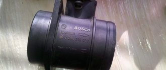
HFM-5 sensor manufactured by Bosch, installed on VAZ cars. The sensor's sensitive element is a thin film on which several temperature sensors and a heating resistor are located. In the middle of the film there is a heating area, the degree of heating of which is controlled using a temperature sensor. On the surface of the film, on the side of the air flow and on the opposite side, two more thermal sensors are located symmetrically, which record the same temperature in the absence of air flow. In the presence of air flow, the first sensor is cooled, and the temperature of the second remains almost unchanged, due to the heating of the air flow in the heater zone. The differential signal of both sensors is proportional to the mass of passing air.
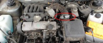
MAF VAZ Bosch
The sensor's electronic circuit converts this signal into a constant voltage proportional to the air mass. This design is called Hot Film (HFM), its advantages include high measurement accuracy and the ability to record reverse air flow, but its disadvantages include low reliability in conditions of contamination and moisture.
In older systems (ECU January-4 and GM-ISFI-2S), other hot-wire mass flow sensors were used, the sensitive elements of which were made in the form of threads. Such sensors are called Hot Wire MAF Sensor. The output signal of these sensors was frequency, that is, depending on the air flow, it was not the voltage that changed, but the frequency of the output pulses. The sensors were less accurate and did not allow registering reverse flow, but these shortcomings were offset by very high reliability.
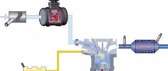
Mass air flow sensor is a very important sensor in any control system. Based on its signal, the cyclic filling of the cylinder is calculated, which is ultimately converted into the duration of the injector opening pulse.
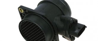
Several types of sensors were installed on VAZ cars: GM, BOSCH, SIEMENS and Russian. In 1999-2004 two types of sensors 0 280 218-037 and 0 280 218-004 were installed on the VAZ conveyor. These sensors produce different output voltage (calibration) parameters at the same air flow rate and interchange (or rather, replacing 004 with 037, as a rule) is only possible with the replacement of calibration tables in the firmware. The same applies to the new sensor 116, which has been installed as standard since the beginning of 2005.
DMRV VAZ 2110
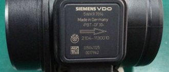
In accordance with the current documentation, three modifications of the air flow sensor HFM5 from BOSCH are allowed for use on VAZ. The VAZ catalog refers to catalogs of spare parts for specific vehicles. Unfortunately, only the last three digits of the “Bosch” catalog number are present on the sensors, and the VAZ number is missing. Historically, the 004 sensor was the first to be introduced in projects with calibrations M1V13O54, M1V13R59, M1V05F05 and M7V03E65 (as well as J5V05F16, the first unofficial version was January 5.1). The first two projects are easily identified by their appearance because... They are without a neutralizer and they used a resonant knock sensor. Then these first two projects were discontinued in production and all further projects (with calibrations of subsequent series) began to be equipped with 037 sensors. Simultaneously with the termination of the two above-mentioned projects, the M7V03E65 project also began to be equipped with an 037 sensor. Modification 037 differs from 004 by modifying the internal air channel of the sensor in order to eliminate air flow pulsations that occur in 004 even with laminar air flow in the intake manifold. At the same time, characteristic 037 has shifted compared to 004. It is believed that in the presence of oxygen feedback, these differences are compensated, which is why the calibration of the M7V03E65 project was not changed when changing the sensor. Since October 2004, the main sensor has been 116. Modification 116 is intended for projects with new generation controllers Bosch M7.9.7 and its domestic analogues - January 7.2, parallel production of which was started by Itelma and Avtel. The calibration of the sensor and its design differ from 004 and 037. The sensor is supplied only assembled, with a code and is marked with a green circle. The element itself has a modified design. In 2006, to complicate the theft or substitution of mass air flow sensor elements, special unidirectional bolts were used to secure the sensing element in the housing. On some classic cars, together with the January 7.2 ECU, Siemens-VDO sensors (5WK97014. AVTEL) were used:
They differ in calibration (from zero volts) and connection diagram. Sensor connection - 1 - 12 volts; 2 - 5 volts; 3 — air flow signal output; 4 — air temperature signal output; 5 is a general minus.
What is a DMRV?
This device is very necessary in order to determine the volume of air that fills the combustion chambers when the engine is running. The sensor is usually installed after the air filter in the power system.
When driving, the automobile power unit is supplied with 1 volume of fuel, as well as 14 equal parts of air. This prepares the correct fuel-air mixture. This is the key to proper operation of the motor in the most optimal modes for it. For any violation of this ratio, the car owner will observe either increased fuel consumption, or a decrease in the power of the power unit, or both. If you know the signs of a malfunction of the mass air flow sensor, it is easy to identify a breakdown of the device.
The mass air flow sensor is necessary in order to accurately measure the required amount of air. This amount is calculated in the sensor itself and then sent to the ECU, where, based on these data, the required amount of fuel will be calculated.
The more the driver presses the accelerator pedal, the more air enters the combustion chambers. The sensor records the amount and sends a special command to the ECU to increase the volume of injected fuel. If the car is to run or drive more smoothly, then a small amount of air will be needed. This is why you need a mass air flow sensor. It measures the required volumes of air for engine operation with maximum accuracy.
Measuring the volume of air means determining the load that will be applied to the motor. When you press the accelerator pedal, the throttle valve opens and the volume of air received increases.
Sensor device
The sensor itself is a combination of two sensors - control and working, as well as a heating resistor.
View of the flow meter from the grid side.
The sensor is disassembled.
The platinum thread is visible in this photo.
As a result, air flow and temperature are converted into electrical impulses understandable to the ECU. This is a very gentle and accurate device; it allows you to calculate the cyclic filling of the cylinders with air and updates the parameters every 0.1 s.
Mass air flow sensor diagram.
The working body of the sensor is a heated platinum thread. It heats up to operating temperature (from 100 to 1000 degrees), and when air enters, it cools down. The amount by which the filament temperature drops is converted into an electrical signal and, based on this value, the ECU calculates the mass and temperature of the air entering the combustion chamber. And based on this data, it prepares the required portion of fuel. In short - yes.
Replacement and installation instructions
After dismantling the old non-working sensor, before purchasing, you can ask a friend for a temporary air flow sensor from his car, and then check it in your 2110. If with another sensor the engine works without interruptions, the consumption does not increase, then it’s time to replace your flow meter. This is the simplest diagnosis that can be carried out when the first signs of a malfunction appear.
We have studied the malfunctions and symptoms, what a mass air flow sensor is is now clear. If we succeed in checking, and we know that the flow meter is faulty, all that remains is to replace it. To do this, you need to prepare a replacement unit (you can buy a non-standard model) and a screwdriver. Visual inspection implies analysis, but let’s repeat it again:
- You need to turn off the engine and remove the key from the ignition.
Installing a new element is done in exactly the same way.
The mass air flow sensor (MAF or flow meter) is an important part of the car, the proper operation of which determines the engine power and its fuel consumption. You can find it under the hood of the car, where it is located between the air filter and the air pipe directed to the throttle valve. The task of the mass air flow sensor is to measure the amount of air passing into the cylinders and transmit this information to the electronic control unit, that is, the “brains” of the machine. Based on the data from the mass air flow sensor, the control unit decides whether to increase or decrease the air supply to the combustible mixture.
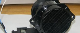
If a mass air flow sensor fails, it is almost never repaired, but simply replaced with a new one. Its design is quite simple, and it consists of a housing in which a device for measuring air flow is placed - a hot-wire anemometer. It is enough to damage the diagnostic device during the process of dismantling the mass air flow sensor or cleaning it, and the entire sensor will need to be replaced. It can also fail after a long service life, but you can verify its malfunction only after checking.
Principle of operation
The piston stroke occurs when fuel is burned with air in a ratio of 1:14, maintaining which ensures optimal operation of the power plant. When the proportion decreases or increases, the engine does not stop working, but there is excessive fuel consumption or a decrease in engine operating power. We need a mass air flow sensor so that air flows in portions. The operation of the unit proceeds as follows: the VAZ 2110 air flow sensor calculates the portion of fresh air, and then sends the data to the main computer, which, based on this information, calculates the portion of fuel.
The harder you push the gas, the more filtered air the powerplant requires. The mass flow sensor detects the increase and commands the electronics to increase the amount of fuel. When moving at the same speed, each portion should be equal to the previous one. The mass air flow sensor receives data on the load of the power unit, and then calculates the required portion of air. When the driver presses the pedal, the throttle valve opens, thereby increasing the volume of intake air - the load increases. When the pedal is released, the load drops.
Damaged sensor due to dust
Connecting the MAF air sensor VAZ 2112
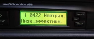
If the mass air flow sensor is operational, then when the engine is running at 900 rpm, the volume of air used will be at least 10 kg per hour. When the speed increases to 2 thousand, this figure will increase to approximately 20 kg. If the volume of air at such speeds drops, the dynamics of the vehicle will also decrease, and accordingly, this will lead to a decrease in gasoline consumption.
If these indicators increase, this will also contribute to an increase in fuel volume. Deviations of the parameter by 2-3 kg should not be allowed, since in this case the operation of the power unit may be incorrect.
Basic faults
The mass air flow sensor rarely fails and requires repair, but it is important to know what the signs of its malfunction are:
- Fuel consumption increases. This can be determined by the on-board computer. If the flow meter malfunctions, fuel consumption increases by a liter or more.
- The car's power decreases.
- Uneven operation of the power unit. The car either accelerates slowly or picks up speed too quickly.
- The engine does not start or does not start the first time.
- Idle speed is floating.
The listed signs do not necessarily indicate a breakdown of the flow meter; the reasons may be the malfunction of other devices, which will require their repair. Therefore, it is necessary to check the serviceability of the flow meter.
What are the malfunctions of the mass air flow sensor in the VAZ-2110
The MAF indicators determine the correct mixture formation of the air-fuel mass in the VAZ-2110. Malfunctions and inaccuracies in the coordinated operation of all components of a single sensor system provoke problems in the operation of the device, and it may also be impossible to start the engine in the car.
DMRV service life
The service life of the mass air flow sensor directly depends on the purity of the air passing through it. The probable cause of flow meter failure as a result of contamination of the heating elements of the flow meter can be identified by removing the sensor and visually inspecting their condition. Deposits on working surfaces will indicate the need to replace the unit or attempt to clean the deposit.
You can extend the service life of the mass air flow sensor by independently monitoring the condition of the engine air filter element and promptly replacing it with a new one. For very dusty Russian roads, which is observed in most regions, the filter may need to be replaced several times in one year or every five to six thousand kilometers. At the same time, the official maintenance regulations for most cars specify a replacement interval no more often than a visit to the next maintenance. Depending on the production, the vehicle service interval can be 10,000 km or 15,000 km.
Types of mass air flow sensors
We will consider a sensor that makes it possible to determine the volume of incoming air using the example of the VAZ 2110. In the VAZ-2110, as in other cars, the device is located inside the air pipe, near the filter, and is responsible for recording the air flow coming out of the filter.
Mass air flow sensors are constantly being improved; today there are several meters that calculate consumed air:
- The main component is a pitot tube. The plate fixed in the sensor changes position under the influence of air flow. The inclination angle of the plate is measured by a potentiometer, which in turn changes the resistance. This serves as a signal for the control unit to determine the volume of incoming air.
- The mass production of modern mass air flow sensor devices requires the presence of hot-wire measuring mechanisms in the sensors. The heat exchanger contains 2 thin plates made of platinum. After energy is supplied to the plates to warm them up, one of them remains working, and the second - control. The MAF sensor in this design makes it possible to ensure a constant, identical temperature touching the 2 plates.
- The working elements of the film meter are silicon wafers coated with platinum.
Design and purpose of the air flow sensor VAZ 2107
The electronic engine control unit receives information about the amount of air entering the combustion chambers of the cylinders. Based on these data, the dosage of gasoline intake is calculated to form the optimal composition of the air-fuel mixture. DMRV VAZ 2107 (injector) is installed between the air filter and the throttle valve. The speed of air flow passing through the sensor is measured by monitoring the temperature of the electrical conductors. The sensor contains two conductive platinum threads. One is blown by passing air, the second serves for control. The passing air cools the first conductor and its resistance decreases. The degree of cooling, and, consequently, the amount of air passed, can be determined by the difference in resistance of the two threads: the larger the volume of air passes, the more the conductor is cooled and the more its resistance decreases. Specific calculations are made by the on-board computer based on algorithms that take into account not only the difference in the resistance of the threads, but also the current temperature of the control conductor.
Verification methods
There are several ways to check the mass air flow sensor with your own hands.
Shutdown
One way to check the flow meter is to turn it off. To do this, you need to remove the connector that connects the mass air flow sensor to the VAZ 2110 system.
Disconnecting the connector from the device
In this case, emergency mode is activated, the amount of air required is calculated based on the throttle position. If the car moves more dynamically with the sensor disabled, it needs to be replaced or repaired; perhaps cleaning will help.
Checking with a multimeter
To check, you need a multimeter and knowledge of repairs and how to handle the tester. The measuring device must be set to constant pressure measurement mode, designated by the letter V or DCV.
Multimeter for testing
To understand the operation of the mass air flow sensor, you need to know its pinout:
- a pink or red-black wire leads to the central unit;
- green wire – grounding;
- The white-gray wire is intended for voltage output;
- The yellow wire is used to supply current to the signal input.
How to check the mass air flow sensor for serviceability
There are several basic methods for checking the mass air flow sensor, which allow you to verify its malfunction.
Checking the mass air flow sensor in motion
The easiest way to diagnose a flow meter is to analyze the operation of the engine when the sensor is forcibly turned off. The check proceeds as follows:
- It is necessary to open the hood and disconnect the connector from the mass air flow sensor. After this, close the hood;
- Next, get behind the wheel of the car and start the engine. The car should begin to operate in emergency mode, in which the Check Engine light will light up. In such a situation, the amount of air in the fuel mixture will be determined depending on the throttle position;
- Try driving the car and pay attention to its dynamics in comparison with how the car worked before the mass air flow sensor was turned off. With the sensor turned off, the car should become “more lively”, that is, accelerate faster. If this is the case, then we can confidently talk about problems with the mass air flow sensor.
It is highly not recommended to operate a car for a long time with the mass air flow sensor turned off.
Checking the mass air flow sensor with a multimeter
You can diagnose a problem with the sensor using a multimeter. To do this, you must first understand the design of the device and its “pinout,” that is, the wiring of the wires on the board. There are 4 wires coming out of the mass air flow sensor. Depending on the MAF model and manufacturer, their colors may vary, but in most cases they are as follows:
- Pink (or pink-black): wire to main relay;
- Green: wire to ground;
- Gray: wire to power;
- Yellow: signal input.
To check the mass air flow sensor, the multimeter must be set to constant voltage measurement mode and set the limit to 2 Volts. Next, you need to turn on the ignition, but do not start the engine. Once this is done, connect the multimeter's red lead to the sensor's signal input (yellow wire) and the black lead to ground (green wire). This can be done without “exposing” the wires by inserting the probes of the diagnostic device through the rubber seal of the connector.
Based on the measurement results, conclusions can be drawn about the state of the sensor:
- Fully serviceable device (new): 0.996 - 1.01 Volts;
- The sensor is in good condition, but has already worked: 1.01 - 1.02 Volts;
- The sensor has been working for a long time, but is still working: 1.02 - 1.03 Volts;
- The mass air flow sensor will soon need to be replaced: 1-03 - 1.04 Volts;
- The flow meter is close to failure, but continues to cope with the tasks: 1.04 - 1.05 Volts;
- The sensor needs to be changed: 1.05 Volts and above.
Some modern on-board computers allow you to view the voltage on the mass air flow sensor. In such situations, you can do without a multimeter.
Visual inspection of the mass air flow sensor
Experienced motorists can determine a malfunction of the mass air flow sensor by its appearance. The first step is to remove the mass air flow sensor, and then inspect it carefully. Signs of a malfunction are liquid getting into the air pipe and the mass air flow sensor (or the presence of mechanical damage).
Most often, liquid may end up in the sensor for the following reasons:
- Increased oil level in the crankcase. In such a situation, oil enters the sensor;
- Clogged oil sump of the crankcase ventilation system;
- Untimely replacement of the air filter, due to which dirt gets onto the MAF hot air anemometer.
The easiest and most reliable way to diagnose problems with the mass air flow sensor is to replace it with a working device. For example, you can remove a suitable working sensor from another car, install it and make sure that engine operation has stabilized. In such a situation, you can immediately go buy a new sensor without diagnosing it with a multimeter or other methods.
Symptoms of a malfunction of the mass air flow sensor on a VAZ-2110
Now about the symptoms of a malfunction of the mass air flow sensor. You need to understand that you can definitely blame the mass air flow sensor only after accurate computer diagnostics of the engine management system. Even the on-board computer can easily make mistakes. However, we will try to identify the breakdown without involving specialists.
Symptoms of a sensor malfunction may coincide with symptoms of other malfunctions :
- Increased or floating idle speed.
- It is impossible to adjust the CO level at idle.
- The engine stalls immediately after starting, the speed is maintained only when the throttle is open.
- Increased fuel consumption.
- The Check Engine light comes on.
- Dips when changing speed, loss of power and dynamics.
The symptoms, as we see, are standard for any malfunction of the power and ignition systems. This means that a more detailed check and verification of the parameters with the nominal ones is necessary.
Check: parameters and compatibility
Sensor for Bosch M 7.9.7 controller – number 0 280 212 116 according to the VAZ catalog.
The difficulty in calculating the parameters and ratings of the sensor lies in the fact that different devices with different ratings were installed at VAZ at different times and on different engines . These ratings were programmed into the electronic control unit and if we install a sensor of a different type (although visually it may be exactly the same), the control system will no longer work correctly. Dozens were equipped with sensors from GM, Bosch, Siemens , and a domestic sensor from Arzamas or Saratov .
The calibration for each of them is different. Only after 2004 did VAZ decide on the type of sensor and its ratings - this is a Bosch device of the HFM5 type in three modifications:
- the first was the mass air flow sensor HFM5-4.7 , according to the Bosch catalog its number is 0 280 212 004, and according to the VAZ catalog it is 21083-1130010-01;
- HFM5-4.7 with article number 0 280 212 037 (21083-1130010-10 according to the VAZ catalogue);
- HFM5-CL , catalog number 0 280 212 116 or 21083-1130003-20 according to the VAZ book.
Peculiarities
We conclude that the sensor is selected not by the number of valves or engine size, but solely by the firmware version and ECU model.
Bosch sensor (21083-1130010-01) for controller January version 5.1.
For example, for the Bosch M7.9.7 ECU it is necessary to use the Bosch mass air flow sensor 0 280 212 116, and for the January controller version 5.1 - only Bosch 21083-1130010-01. That is, even if a sensor is installed from the factory that does not correspond to the ECU firmware, you cannot expect correct engine operation and normal fuel consumption. By the way, there are often cases when sensors were installed from the factory that do not correspond to the firmware version. Therefore, the first check is for compatibility. And then we take a multimeter and go into battle.
The second way is using a multimeter
Before performing these diagnostics, it should be noted that this will only work with a Bosch mass air flow sensor. Before performing the test, set the limit on your multimeter to 2 V, and then switch the device to constant voltage operation.
Turn on the ignition and connect the red wire to the yellow one on the block. Connect the black wire to the green one. At this moment the engine should not be running. Measure the voltage If the reading is between 1.01 and 1.02 then everything is fine. The multimeter shows voltage up to 1.03 - there is nothing to worry about, this is acceptable. The limit level is 1.05. If it is higher, then you can again look for the cause of the breakdown.
Prevention and testing of mass air flow sensor on VAZ 2110
As a preventive measure, we can recommend timely replacement of the air filter. The use of sports zeros shortens the life of the flow meter. In any case, regular cleaning of the air flow sensor will not hurt.
- We disconnect the sensor connector, having first removed the ground from the battery.
- Carefully unscrew the flow meter housing from the intake manifold flange.
- If dust deposits are detected, blow out the cavities with compressed air.
- Of course, you also need to clean the air duct and air filter box at the same time.
Tip: It is recommended to repeat this operation every time you replace the air filter.
If the contamination is severe (with oil and moisture), you can use a special cleaner for flow meters or carburetors; the manufacturer does not matter. To do this, it is necessary to direct the jet not only to visible sensors, but also to hidden cavities where the platinum resistor (thread) is located.
After this, the flow meter is installed in its regular place and the functionality of the electronic part is checked.
VAZ air flow sensor pinout. Checking and repairing the air flow sensor
Based on the signal from the mass air flow sensor (MAF), the cyclic filling of the cylinder is calculated, which is ultimately converted into the duration of the injector opening pulse. If it does not work correctly, the car consumes more gasoline than necessary. Such a sensor is installed on the second path, immediately behind the air filter and connected to the electrical system, which is controlled by a six-pin block of wires.
There are quite a few different types of mass air flow sensors: mechanical, ultrasonic, hot-wire and some others.
In this case, we will consider the design of the HFM-5 hot-wire sensor from Bosch, which is most often installed on VAZ cars. The sensor's sensitive element is a thin film on which several temperature sensors and a heating resistor are located. In the middle of the film there is a heating area, the degree of heating of which is controlled using a temperature sensor.
On the surface of the film, on the side of the air flow and on the opposite side, two more thermal sensors are located symmetrically, which record the same temperature in the absence of air flow. In the presence of air flow, the first sensor is cooled, and the temperature of the second remains unchanged, due to the heating of the air flow in the heater zone. The differential signal of both sensors is proportional to the mass of passing air.
- 1 - dielectric diaphragm
- H - heating resistor
- SH - Temperature sensor naked. resistor
- SL - Air temperature sensor
- S1 and S2 - temp sensors before and after the heater.
- QLM - air flow mass
- t—temperature
The sensor's electronic circuit converts this signal into a constant voltage proportional to the air mass. This design is called Hot Film (HFM), its advantages include high measurement accuracy and the ability to record reverse air flow, but its disadvantages include low reliability in conditions of contamination and moisture.
To measure the amount of air that enters the engine means to determine the engine load. When the driver presses the gas pedal, the throttle valve opens and the amount of intake air increases. At the same time, we say that the load has increased. When you release the pedal, the load drops. It's quite simple. However, this is only at first glance. If we take into account the fact that in real driving conditions the engine often changes operating modes and the incoming air in the intake system participates in several gas-dynamic processes, then the problem of measuring the air in the system is not so simple.
In older systems (ECU January-4 and GM-ISFI-2S), other hot-wire mass flow sensors were used, the sensitive elements of which were made in the form of threads. Such sensors are called Hot Wire MAF Sensor. The output signal of these sensors was frequency, that is, depending on the air flow, it was not the voltage that changed, but the frequency of the output pulses. The sensors were less accurate and did not allow registering reverse flow, but these shortcomings were offset by very high reliability.
Several types of mass air flow sensors were installed on VAZ cars: GM, BOSCH, SIEMENS and Russian-made. In 1999-2004 Two types of sensors were installed on VAZ cars: 0 280 218-037 and 0 280 218-004. These sensors produce different output voltage (calibration) parameters at the same air flow rate and interchangeability (or rather, replacing 004 with 037) is only possible with the replacement of calibration tables in the firmware. The same applies to the new sensor 116, which has been installed as standard since the beginning of 2005.
The sensor is supplied only assembled, with a code and marked with a green circle.
On some classic cars, together with the January 7.2 ECU, Siemens-VDO sensors (5WK97014. AVTEL) were used:
They differ in calibration (from zero volts) and connection diagram.
Methods for checking sensor functionality
How to check the flow meter yourself? There are several diagnostic options, we suggest you familiarize yourself with each of them (the author of the video is the Bezdelnik TV channel).
The first method is to disable the sensor
This verification method is the simplest. Every car owner can do it. The first step is to turn off the sensor. To do this, you just need to unplug the connector. Then you should start the engine. As a result, the ECU controller will go into emergency mode. And the supply of the fuel mixture will be regulated only using the throttle valve. Idle speed will be around 1500 rpm. After this, you need to check in by car. If the car has improved its dynamic acceleration characteristics, then it makes sense to look for signs of a malfunction of the mass air flow sensor.
Method No. 2 - flashing the electronic control unit
If the standard firmware has been changed, then it is unknown what reaction of the controller is programmed in it in case of an emergency. In this case, you should try to insert a 1mm thick plate under the throttle stop. The turnover should increase. Now you need to pull out the chip from the air flow meter. If the power unit continues to work, then the cause of the malfunction is the firmware.
Method No. 3 - installing a working sensor
Install a known good part and start the engine. If after replacement it begins to work better, the motor does not stall, then replacement or repair of the device is required.
Method No. 4 - visual inspection
To do this, use a Phillips screwdriver to unscrew the clamp holding the air collector corrugation. Then you need to disconnect the corrugation and inspect the internal surfaces of the air collector corrugation and the sensor.
Inspection of duct corrugation
There should be no traces of oil or condensation on them, the surfaces should be dry and clean. If you do not take care of the air filter and change it rarely, then dirt can get on the sensitive element of the sensor and cause it to break. This is the most common malfunction. Traces of oil may appear in the flow meter if the oil level in the crankcase is high, or if the oil sump of the crankcase ventilation system is clogged. If necessary, you need to clean the surfaces using special cleaning products.
Replacing the sensor - instructions
Using a screwdriver, unscrew the clamp of the air intake corrugation at the sensor outlet, pull it off and carefully inspect the internal surfaces of the sensor itself and the corrugation. These surfaces must be dry and clean; traces of condensation and oil are unacceptable. If the air filter is changed rarely, then dirt getting on the sensitive element of the sensor is the most common cause of its breakdown in VAZ cars.
There may be oil in the mass air flow sensor as a result of an increased oil level in the engine crankcase, or the oil sump of the crankcase ventilation system is clogged.
Next, unscrew the 2 screws of the sensor with a 10mm wrench and remove it from the air filter housing. There should be a rubber sealing ring on its front part (at the entrance edge). It prevents unfiltered air from being sucked into the intake tract through the sensor.
If the ring is out of place and stuck somewhere in the air filter housing, then there will be a thin layer of dust on the inlet mesh of the sensor itself. This is the second reason that destroys the mass air flow sensor ahead of time.
Correct assembly should take place in the following sequence: put a sealing rubber band on the sensor, check the sealing skirt, then insert everything together into the filter housing.
This concludes the visual check of the mass air flow sensor at home. You can check its operation 100% only with the help of special equipment in a car service center. For example, using a technique for assessing the oscillogram when the throttle is sharply opened to the cutoff mode (a motor tester is needed), or assessing the oscillogram when the ignition is turned on.
Resuscitation of a damaged air flow sensor is successful in no more than 5% of cases. In extreme cases, you can rinse with ethereal liquid to clean matrices and optics. It will evaporate without a trace. After making sure that there is no more dust or debris in the device, you can dry it thoroughly and put it back in place. Sometimes after such a simple procedure the device will work.
On most foreign cars, a mass air flow sensor was installed until 2000; subsequent generations of models began to be equipped with a pressure controller. Replacing a non-working sensor is simple and can be done on your own without any problems, you just need to buy a mass air flow sensor that matches the ECU firmware version. Its price is around 3,000 rubles, depending on the manufacturer.
External signs of a malfunction of the VAZ 2110 mass air flow sensor
This is the third way to diagnose the sensor. To determine its serviceability, carefully inspect the internal cavities of the air pipe where the mass air flow sensor is mounted. In order to do this, you will need a shaped screwdriver. Loosen the clamp and disconnect the corrugated pipe. The surface of the corrugation should be as dry as possible, without an oil film.
It should be noted that the main signs of a malfunction of the mass air flow sensor are dirt on the working surface. It is formed due to the fact that the air filter was not replaced in time. Oil deposits will tell the driver that the oil level in the lubrication system is high or that the oil cutter is not working properly. With these signs, the sensor may still work, but will soon fail.
Next you need to completely remove the mass air flow sensor. You will find signs of a malfunction after a visual inspection of the device. To carry out this operation, you will need a 10mm wrench. Unscrew the two screws and remove the device from the air filter housing. A rubber seal will come out with the sensor. If the seal remains in the housing, this is the main sign of imminent failure.
Replacing the air flow sensor
To replace the sensor with your own hands, you need to prepare a shaped screwdriver and a “10” key.
The replacement procedure consists of the following steps:
- First you need to turn off the ignition and open the hood.
- Then you need to disconnect the negative terminal on the battery.
- At the next stage, you need to loosen the clamp with which the corrugation is attached to the mass air flow sensor.
- Next, remove the corrugation from the pipe.
- Then you need to bend the comb and disconnect the sensor connector.
Disconnecting the sensor connector - Then, using a key set to “10”, you need to unscrew the sensor mounting bolts to the air filter housing.
- Now you can remove the mass air flow sensor.
- Installing the sensor yourself is carried out in the reverse order.
Thus, if the car stalls and has all the signs of a breakdown of the mass air flow sensor, then before you start repairing it, you should check the level of its signal, it should not be low, perform a full diagnosis of the car and repair all faulty components and parts.
It is important to undergo regular vehicle inspections and perform timely maintenance, then the parts and components will last longer.
Video “Features of replacing a flow meter in a garage”
How the replacement procedure is carried out and what points should be taken into account when performing this task - find out from the video below (author - channel In Sandro's Garage).
Did you like the article? Share with friends:You may also be interested inPower steering
Installation of the UAZ 417 distributor drive: order and ignition circuit, adjustment and configuration of the lock The UAZ distributor is considered one of the important components of the ignition system in a vehicle. Correct adjustment of this… Media devices
Operating instructions for Sony radio: all models, pinout and connection of the car radio Probably every person has heard about Sony at least once in their life. This brand has been producing equipment for many years... Security system
Car alarm STARLINE B9: installation and operating instructions (download in PDF format), connection diagram and key fob programming The Starline B9 manual includes installation recommendations, as well as diagrams necessary for proper connection... Ignition system
Procedure and ignition diagram for ZIL 130: instructions for installing and connecting a contactless system. A modern car is a complex system of components and mechanisms that must interact smoothly. Ignition system… Security system
Car alarm STARLINE A91: operating and installation instructions (download and read in PDF format), how to install auto start and typical connection diagram The Starline A91 security system, equipped with an automatic engine start module, provides reliable protection for cars
Adjustment and ignition order of the GAZ-53: how to set the marks, video of installing the distributor drive The ignition system plays an important role for the internal combustion engine. The timeliness and power of spark formation depends on the uninterrupted operation of the safety protection system.
Why does the ELM327 Bluetooth not connect to the ECU, there is no communication and connection with the unit, the adapter does not see it? The procedure for checking the performance of a car engine can be performed both visually and with the help of an additional
Replacing the Lada Granta alternator belt with air conditioning and its tensioner: how to remove, tension and change. Power to the vehicle's electrical equipment while driving is provided by a generator, which operates thanks to a belt drive.
Types of mass air flow sensors, their design features and operating principle
Three types of VU meters are most widespread:
- Wire or thread.
- Film.
- Volumetric.
In the first two, the operating principle is based on obtaining information about the mass of the air flow by measuring its temperature. The latter may involve two accounting options:
- By changing the position of the slider, driven by a special blade, which is affected by the air flow passing through the device. Considering the presence of rubbing mechanisms, the level of reliability of such structures is quite low. This was the main reason for the refusal of car manufacturers from sensors of this type. For reference, here is a simplified example of the design of a volumetric flow meter.
Volumetric air flow sensor device - By counting Karman vortices. They are formed if a laminar air flow washes over an obstacle whose edges are quite sharp. The frequency of the vortices breaking off from them is directly related to the speed of air flow passing through the device.
Vortex sensor design (widely used by Mitsubishi Motors)
Designations:
- A – pressure measurement sensor to record the passage of the vortex. That is, the frequency of pressure and vortex formation will be the same, which makes it possible to measure the flow of the air mixture. At the output, using an ADC, the analog signal is converted to digital and transmitted to the ECU.
- B - special tubes that form an air flow similar in properties to laminar.
- C – bypass air ducts.
- D – column with sharp edges on which Karman vortices are formed.
- E – holes used to measure pressure.
- F – direction of air flow.
Wire sensors
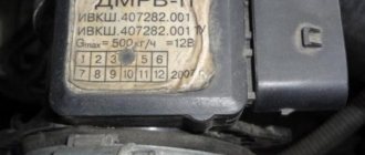
Until recently, thread mass air flow sensor was the most common type of sensor installed on domestic cars of the GAZ and VAZ model range. An example of a wire flow meter design is shown below.
Design of volumetric meter IVKSH 407282.000
Designations:
- A – Electronic board.
- B – Connector for connecting the mass air flow sensor to the computer.
- C – CO adjustment.
- D – Flow meter housing.
- E – Ring.
- F – Platinum wire.
- G – Resistor for temperature compensation.
- N – Ring holder.
- I – Electronic board casing.
Operating principle and example of a functional diagram of a filament VU meter.
Having understood the design of the device, let's move on to the principle of its operation, it is based on the hot-wire method, in which a thermistor (RT), heated by the current passing through it, is placed in the air flow. Under its influence, the heat transfer changes, and, accordingly, the resistance RT, which makes it possible to calculate the volumetric flow rate of the air mixture? using King's equation:
where I is the current passing through RT and heating it to temperature T1. In this case, T2 is the ambient temperature, and K1 and K2 are constant coefficients.
Based on the above formula, you can derive the volumetric air flow rate:
An example of a functional diagram with bridge connection of thermoelements is shown below.
Typical functional diagram of a wire mass air flow sensor
Designations:
- Q - measured air flow.
- U – signal amplifier.
- RT - thermal resistance wire, usually made of platinum or tungsten filament, the thickness of which is in the range of 5.0-20.0 microns.
- RR – temperature compensator.
- R1-R3 are ordinary resistances.
When the flow velocity is close to zero, the RT is heated to a certain temperature by the current passing through it, which allows the bridge to be kept in equilibrium. As soon as the flow of the air mixture increases, the thermistor begins to cool, which leads to a change in its internal resistance, and, as a result, an imbalance in the bridge circuit. As a result of this process, a current is generated at the output of the amplifier unit, which partially passes through the temperature compensator, which leads to the release of heat and makes it possible to compensate for its loss from the flow of the air mixture and restores the balance of the bridge.
The described process allows you to calculate the flow rate of the air mixture based on the amount of current passing through the bridge. In order for the signal to be perceived by the ECU, it is converted into a digital or analog format. The first allows you to determine the flow rate by the frequency of the output voltage, the second - by its level.
This implementation has a significant drawback - a high temperature error, so many manufacturers add a thermistor similar to the main one to the design, but do not expose it to air flow.
During operation, dust or dirt deposits may accumulate on the wire thermistor; to prevent this, this element is subjected to short-term high-temperature heating. It is performed after the internal combustion engine is turned off.
Cleaning the sensor
If you observe signs of a malfunction of the mass air flow sensor, then you can try cleaning the device.
By the way, this is the most expensive sensor of all in the line of front-wheel drive VAZ cars. But if yours is broken, don’t rush to change it. There is a small chance of restoring his “health”. For the cleaning process you will need a special liquid that is used to clean the carburetor. Star keys are also useful. Unscrew the clamp, as well as the two “10” bolts. Remove the pipe and take out the sensor. Spray the liquid onto the wire and tube. Work with extreme care, wait until this liquid has completely evaporated and leave the device to dry.
While the device is drying, remove the throttle assembly. You will see plaque inside the throttle assembly. It needs to be removed with liquid. This dirt causes problems with the entire system. Because of it, problems with the mass air flow sensor appear, signs of a malfunction of the VAZ 2115, which bother beginners on automobile forums.
Do not remove the throttle cable. Place the knot on a cloth and treat particularly dirty areas with the liquid. Don't forget to clean the idle air control valve and the space underneath it.
After this, most likely, all signs of problems with the mass air flow sensor will go away, of course, provided that the sensor has no mechanical damage. Therefore, do not wait until you have the first signs of such problems, but take such prevention this coming weekend. It won't take you much time, and your car will truly breathe. You won't recognize your engine. It will start much better, its traction will improve, and you will notice an increase in the power of your engine.
Carry out such preventive maintenance regularly, and your car will thank you.