The operation of the contact transistor system is based on the use of semiconductor devices. The advantages of the contact transistor system compared to the battery ignition system are as follows:
- A small transistor control current passes through the contacts of the breaker, and not the current (up to 8 A) of the primary winding of the ignition coil (erosion and wear of the contacts are eliminated).
- The high voltage current and spark discharge energy increase (this allows the gap between the spark plug electrodes to be increased, makes it easier to start the engine, and makes the engine more economical).
First, let's figure it out
How does a contact-transistor ignition system work?
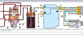
If the ignition switch 17 is turned on and the breaker contacts are open, then the transistor 21 is locked, since there is no current in its control circuit, i.e. in the emitter-base junction. Current does not pass between the emitter and collector to ground, since the resistance of this junction is very high. When the breaker contacts are closed, current flows in the transistor control circuit (emitter-base), causing the transistor to open. The control current is small (about 0.8 A) and decreases to 0.3 A with increasing speed of the chopper cam. In the contact-transistor ignition system there are two low voltage circuits: the transistor control circuit and the operating current circuit.
Transistor control circuit: positive terminal of the battery 16 - ignition switch 17 - terminals VK-B and K of additional resistors 14 - primary winding 4 of the ignition coil 5 - terminal of the transistor switch 1 - transition electrodes emitter - base of the transistor 21 - primary winding of the pulse transformer 20 - terminal P – contacts 11 and 12 of the breaker – ground – negative terminal of the battery. When the transistor control current passes through the emitter-base junction, the emitter-collector resistance significantly decreases, and the transistor opens, including the operating current circuit (7-8 A).
Low voltage operating current circuit
Positive terminal of the battery 16 - ignition switch 17 - terminals VK-B and K of additional resistors 14 - primary winding 4 of the ignition coil 5 - terminal of the transistor switch 1 - electrodes of the emitter-collector transition of the transistor 21 - terminal M - ground - negative terminal of the battery. When the breaker contacts open, the current in the transistor control circuit stops and its resistance increases significantly. The transistor closes, turning off the low voltage operating current circuit. The magnetic flux of the changing field crosses the turns of the ignition coil, inducing an EMF in the secondary winding, resulting in a high voltage (about 30,000 V), and a self-inductive EMF in the primary winding (about 80-100 V).
High voltage circuit
Secondary winding 6 of the ignition coil 5, rotor 9 of the distributor 10 – spark plugs 7 (in accordance with the engine operating order) – ground – secondary winding 6 of the ignition coil 5.
A pulse transformer is needed to quickly turn off the transistor. When the breaker contacts open, a self-induction EMF is induced in the secondary winding of the pulse transformer, the direction of which is opposite to the direction of the operating current at the base-emitter junction. Thanks to this, the magnetic field and current quickly disappear in the primary winding 4 of the ignition coil 5. Diode 19 and zener diode 18 in the forward direction - past the primary winding of the ignition coil.
It must be remembered that the breaker contacts only pass and interrupt the transistor control current of 0.3-0.8 A. If oil gets on them, an oil film or an oxide layer has formed, then the transistor control current will not be able to pass through the contacts. Therefore, the breaker contacts are washed with gasoline and ensure that they are always clean.
General operating principle
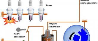
The presence of a contact ignition system in a car means that the ignition of the fuel in the cylinders is carried out upon the appearance of a spark from the spark plug.
In this case, the spark itself occurs when a high voltage pulse arrives from the ignition coil.
The key function is performed by the ignition coil, which, according to its operating principle, resembles a transformer.
It consists of two windings (primary and secondary) wound on a metal core.
First, voltage is applied to the primary winding, after which a current is created in the coil.
As soon as a short-term break in the primary circuit occurs, the magnetic field is leveled, but a high voltage (about 25,000 Volts) appears in the secondary winding.
At this moment, a voltage of 300 Volts is also present on the primary winding.
The reason for its appearance is self-induction currents. It is because of the appearance of this current that the breaker contacts burn and spark.
From the above we can conclude that the secondary voltage directly depends on the following aspects:
- Magnetic field;
- The intensity level of the current drop in the primary winding.
To increase the secondary voltage and reduce the risk of burning the contact group, a capacitor is included in the circuit (installed in parallel). Even with a slight opening, the capacitor is charged.
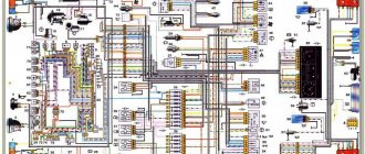
A schematic diagram of the contact ignition system is shown below.
Currently reading Why do spark plugs turn black?
17.1k
Immobilizer locked, how to start the engine
23.5k
The capacitance discharge occurs through the primary winding, through the formation of a reverse voltage pulse current. Thanks to this feature, the magnetic field disappears and the secondary voltage increases.
The optimal capacitor capacity for a contact ignition system is 0.17-0.35 µF. For example, domestically produced Zhiguli cars have a capacitor with a capacitance of 0.2-0.25 μF (at a frequency of 50 to 1000 Hz).
If the vehicle's ignition system operates without failure, the secondary voltage should constantly increase. It depends on two main parameters - the size of the gap between the spark plug electrodes, as well as the pressure in the cylinders of the machine.
For a contact ignition system, this parameter (secondary voltage) should be at the level of 8-12 Volts.
In order for the system to operate without failures, at the moment of interruption the mentioned indicator increases to 16-25 kV. The presence of such a reserve allows you to avoid adverse consequences from certain fluctuations in the ignition system.
The problems mentioned above include adjustments to the composition of the combustible mixture or changes in the distance between the spark plug electrodes.
For example, a decrease in the oxygen level in the fuel-combustible mixture leads to an increase in voltage to 20 kV.
Despite a number of measures taken, the creators of the contact ignition system were unable to completely avoid burning the contact group. The optimal way to reduce this effect is to strictly maintain the gap at a minimum level (0.3-0.4 mm).
As an example, we can cite domestic VAZ cars, in which the gap in the breaker is 0.35-0.45 mm, which corresponds to an angle of 52-58 degrees (provided that the contact group is in a closed state).
If this angle changes, the voltage in the secondary winding is also adjusted. As a result, sparks appear not only on the contacts, but also on the sliders. For this reason, the quality of the spark decreases and the engine loses power.
The reliability of the contact ignition system, which depends on a number of factors, deserves special attention:
- Shape, energy and time of spark appearance;
- The number of sparks in a certain area;
- Secondary voltage (one of the most important characteristics). The larger this parameter, the less dependent the system is on the composition of the combustible mixture and the level of cleanliness of the electrodes.
conclusions
All systems used to ignite a fuel mixture are good in certain areas of mechanical engineering. Everyone is not without their shortcomings. It is not always necessary to create a complex and highly reliable system; sometimes it is much cheaper to use simple and cheaper ones. There is no need to install an expensive ignition system on a car that is much lower in cost than others in its class. Such actions can only increase its cost, but the quality, unfortunately, will remain the same. Why change anything if the ignition system has shown only the best results in many tests?
Device
The ignition system of the GAZ 53 car is currently contactless. Having studied the device and principle of operation, you can simultaneously master troubleshooting skills. This is especially necessary for those who operate GAZ 53. After all, it often happens that there are no good specialists nearby who would help in solving problems that arise. In addition, you will have to pay for their services. The quality of the work done can sometimes be determined after some time. A malfunction that occurs unexpectedly and at the wrong time will create trouble.
System elements
The ignition system of the GAZ 53 car consists of several elements, each of which performs its own function. Knowing them, you can find and fix the problem much faster. The system consists of the following elements:
- Rechargeable battery;
- Switch;
- Spark plug;
- Sensor distributor;
- High-voltage and low-voltage wires;
- Ignition coil;
- Additional starter relay;
- Additional and noise suppression resistor;
- Current indicator;
- Egnition lock.
All constituent elements can be grouped depending on the tasks performed. In this case, they will be included in the appropriate groups. The ignition system of the GAZ 53 car will work correctly when the basic conditions are met:
- Comparison of the moment of spark occurrence and engine operation;
- Sufficient spark power;
- No gaps in sparking.
To supply a spark in a timely manner, you need to carefully correlate the engine operating cycles and the appearance of voltage on the spark plug electrodes. The required spark power, in turn, depends on the voltage, the gaps between the electrodes of the spark plug and the serviceability of the circuit. The lack of a spark leads to a decrease in power and an increase in fuel consumption, so misfires are unacceptable.
A Timely Spark
Comparison of a certain stroke and voltage supply to the spark plugs is the task of the distribution sensor. The contactless ignition system of the GAZ 53 car can be equipped with a magnetoelectric or semiconductor sensor-distributor, which is located inside the distributor. The list of distributor elements includes:
- Sensor-distributor;
- Current carrying plate (runner);
- Centrifugal and vacuum regulator.
The GAZ 53 magnetoelectric sensor is a generator of alternating current pulses, the frequency of which depends on engine speed. This device has eight poles (according to the number of cylinders). During the rotation of the camshaft, and with it the sensor rotor, the poles of the permanent magnet sequentially pass through the poles of the stator winding. As a result of the changing magnetic flux, an induced emf is induced in the winding, which creates a control pulse for the commutator.
The centrifugal regulator rotates the sensor rotor relative to the stator, which, in turn, changes the ignition timing of the GAZ 53. This occurs when the engine crankshaft speed increases. The regulator weights, overcoming the force of the springs, turn the rotor. Thus, the effort must be certain, otherwise it will affect the operation of the GAZ 53.
The vacuum regulator rotates the stator relative to the rotor, changing the angle. It operates depending on the load and engine speed.
Power and spark quality
It's no secret that a good spark is the key to high-quality ignition of a combustible mixture. The ignition system of a GAZ 53 car will have a good spark if the following conditions exist:
- The gap between the spark plug electrodes is correctly adjusted;
- Serviceable ignition coil;
- The desired shape of the commutator pulses;
- Good quality high voltage circuit.
If the gap between the spark plug electrodes is too small, ignition of the air-fuel mixture will be difficult. Because of this, a gap may occur not in sparking, but in ignition. The consequences are the same.
The serviceability of the ignition coil is manifested in its ability to induce the required voltage without interruptions (skips). As a rule, a faulty coil makes itself known by a characteristic decrease in the quality of operation of all eight cylinders. If it is determined that the coil is faulty, then it must be replaced with one of the same type, with the same markings. This GAZ 53 part consists of two windings: primary and secondary. The latter contains many more turns than the first. The windings are wound one on top of the other on a magnetic core. The entire structure is housed in a sealed housing filled with plastic. The malfunction of this part is associated with a short circuit, which can be interturn and to the housing.