Fan control circuit in Niva Chevrolet
Before you begin diagnostics, you need to understand how fan motors work. To do this, you need to study the corresponding electrical diagram:
As can be seen from the diagram, the fans on the Chevrolet Niva are controlled using two ECU outputs:
- One output controls the low speed of the right fan through a resistor.
- The other two turn on the fans at full power.
There is a separate output 75 pin - turns on the right fan for constant rotation when the air conditioner is turned on.
We have already mentioned in one of the articles about the fan operation algorithm, but let us remind you again:
When the temperature reaches 99 degrees, the right fan turns on through a resistor at low speed. If the temperature continues to rise and reaches 100-101 degrees, then two fans turn on. They work until the temperature drops to 93 degrees.
From 2022, according to a new fan control scheme: first, both fans are switched on in series at half power without a resistor, and then both are turned on directly at full power. The scheme is also relevant for Niva Travel.
If nothing like this happens to you, then there is a malfunction. But it should be noted that you should not trust the temperature indicator on the Niva instrument panel. Often, this device shows erroneous data, and overestimated ones. The most accurate devices in this case will be diagnostic equipment or an on-board computer.
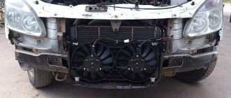
Design and principle of operation
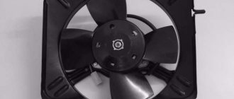
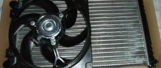
The designers of the Chevrolet Niva used a dual fan unit in the cooling system. This slightly complicated the connection diagram, but sharply increased the efficiency of radiator airflow. The fans are driven by 12-volt DC synchronous motors with a permanent magnet inductor. Electric motors have a closed, non-demountable design and do not require maintenance.
The power of each electric motor is 110 W. The fan assembly draws 18 amps.
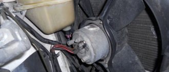
The fans are turned on one by one using an electromagnetic relay controlled by the on-board computer. When the coolant heats up above 99 degrees, the electric fan located closer to the engine air intake starts. The switch-on temperature of the second impeller is 101 degrees. The fan connection diagram is shown below.
The fan power system includes three relays and a resistor, which, if necessary, provides a reduced rotation speed of the first motor. Power is supplied from the battery through fuses that save the wiring and battery in the event of a short circuit. Control signals come from pins 29 and 68 of the motor controller.
The fans automatically turn off when the antifreeze cools to 95 degrees.
Consecutive switching on and off of engines reduces the load on the on-board electrical network. In most cases, it is possible to normalize the temperature only with the help of the first fan. This is especially useful when driving at night, when headlights and side lights put a lot of stress on the generator.
How is diagnosis performed?
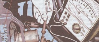
To check the operation of the fans on a Chevrolet Niva, there is a simple test - unplug the coolant temperature sensor. One of the fans should turn on at full power. In this case, you need to start the engine, since on ECU 7.9.7+ the VCO is turned on only when the internal combustion engine is running. If the fan operates, then the problem is with the coolant temperature sensor. As a rule, it shows the “weather” when diagnosing the ECU.
If after removing the chip from the sensor nothing happens, then the reason is definitely not the DTOZH. The next stage is checking the control circuits. For this you will need diagnostic equipment. For example, a free version of the Open Diag program, as well as a diagnostic cable. You can buy the cable here or use the ELM327 universal adapter.
This is what the test of actuators looks like in the Open Diag program. By selecting Fan Relay 1 or 2, you can turn the fan on or off in the Niva during the diagnostic process. Of course, the screenshot is an example. In fact, Niva has three relays.
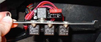
We try to turn on all three relays one by one. If you can’t even hear clicks, then the problem may be in the relays themselves or in the ECU. It would be a good idea to check the 50 Amp fuses next to the relay:
It is worth considering that if a relay malfunctions, all three relays cannot fail at once. One of them will work and continue to turn on the fan. It will be enough to replace it.
To check the fan relay on a Niva, just swap it with its neighbor and check whether the other consumer will work or whether the fan will turn on with the new relay. If not, then most likely the ECU output is faulty.
Another possibility is a blown fuse. This happens during short circuits. As a rule, the positive wire may be broken somewhere and short to ground. Find this location first and then change the fuse. Often, a short circuit can occur in the fan motor itself. Therefore, if when connecting the lamp (which will be discussed a little later), the fuse does not blow, then the problem is in the fan.
If the circuits are working properly, the relays click, and the fans do not work, then the next step is to check the fans themselves. We disconnect the chips from the non-working fans (or one fan), connect a regular 55-watt test light instead of the fans and, using commands sent from the Open Diag program, check whether voltage is coming to the connectors:
- If the voltage comes on (the lamp lights up), the wiring is OK and all that remains is to replace the fan itself.
- If there is no low speed, replace the resistor.
- If the relays click and the lamp does not light up, then the problem is in the wiring and there may be a break somewhere.
Attention! The lamp should work at full intensity. If it burns at full heat, there is a bad mass! You should start checking bulk connections here:
and on the very negative terminal of the battery:
Brown thick wire
Both fans rarely fail. As a rule, low speed or high speed of both fans disappear individually. All three malfunctions can occur at once only if the ECU is broken or the ground is bad.
Causes of malfunction
The first thing you should pay attention to when the system is not working is the state of the fuses, which are located under the front panel, on the passenger side, in a special mounting block. A pair of fuses are responsible for the cooling operation; if the right one fails, then both fans stop working, and if the left fuse blows, then one element can continue to operate.
In addition, the mounting block has three relays that are responsible for operating the fans at different speeds. And if the relay responsible for operation at low speeds burns out, then the cooling system works correctly only at high speeds, and at low speeds the engine begins to heat up. Power is supplied to the relay through a special fuse, which can also fail, causing system failure.
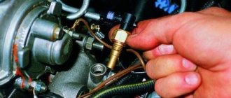
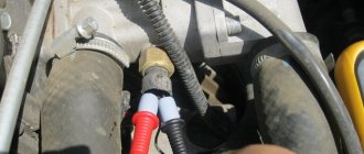
Failure of temperature sensors also affects proper cooling operation. They are located on the engine. They operate when the desired temperature is reached, one when it reaches 90 degrees, and the second when it reaches 101 degrees. It is recommended to start checking with them, this is done this way: the connector is disconnected from the electric motor, and power is supplied to them directly through the battery; if the electric motor is running, then the reason is in the sensors.
If after checking everything, fuses, relays and sensor are in order, you should pay attention to the fans.
Circuit breakers
The electrical circuits of Niva Chevrolet cars produced before and after 2009 are different. In both cases, 50-amp fuses protecting the electric fan power circuits are located in an additional unit. It is located behind the glove box on the passenger side of the cabin. The figure shows where the fan fuses are located.
If the permissible current is exceeded, the insert melts and the circuit opens. Therefore, fuses are the first thing to check if the electric cooling fan does not work. The performance of a part can be assessed visually or using an ohmmeter (multimeter). To do this, you will first have to remove the fuse from the socket.
Relay for starting the fan
The spare block may contain not only the fuses themselves, but also electromagnetic relays . They control the operation of the engine cooling system, the circuits of which are powered by the ignition switch of the on-board computer. The current comes from the battery through the fuses themselves.
The relay operates as follows : at the very beginning, voltage is applied to the output, as a result an electromagnetic field is formed by passing current through the inductive coil. Subsequently, the current passing through the relay starts the engine. If the voltage is removed, the contacts will open due to the spring that is present in the mechanism, and the fan itself will stop.
There are several ways to check the operation of the relay . The simplest method is to replace the relay with the same working one and check the condition of the system. Turn off the engine, then disconnect the temperature sensor connector, after which you will hear a characteristic click of the relay. Then you need to remove and test the output contacts using multimeters, constantly applying voltage to the output. From the temperature sensor, information is supplied to the unit switching device.
The temperature sensor itself is a resistor, the values of which vary in a variable temperature range : from 1.3-1.8 Ohms at 30°C to 155-196 Ohms at 90°C. To give an accurate assessment of its performance, use a thermometer and an ohmmeter, calculating the resistance at different temperatures. To check, the part is removed and then immersed in an aqueous environment. The sensor can be found near the main exhaust system. It is dismantled using a spanner.
Power sensor
The control unit receives information about the antifreeze temperature from a temperature sensor. It is a resistor whose resistance changes with heating and cooling: from 1.3-1.8 kOhm at 30℃ to 155-196 Ohm at 90℃. You can check its performance using an ohmmeter and a thermometer. To do this, you need to remove the part, immerse it in water and measure the resistance at different temperatures.
The sensor is located on the engine head in the area of the exhaust pipe of the cooling system. You can unscrew it with a socket or socket wrench.
We recommend watching a video that shows where the sensor is located and how to check:
Typical breakdowns
The most common reasons : malfunction of the temperature sensor, damage to the power system, malfunction of the wires passing from the battery to the ignition switch, inoperability of the second fan.
The main reasons may be sensor defect , failure of a fuse or electromagnetic relay. If the performance of the left fan is reduced, this may indicate a breakdown of the “resistance”, temperature sensor, damage to the fuse or relay.
When turning on two fans simultaneously, you should pay special attention to one more device in the circuit of the first electric motor. Failure to operate occurs when the relay itself is damaged or the temperature receiver for cooling the liquid is damaged.
All of the above parts are not repaired . After each damage they are replaced with new ones.
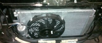
Replacing fans
If the fan motors do not start when the wires from the battery are connected directly to the power terminals, the devices must be replaced.
To do this, you will need a set of wrenches ranging in size from 10 to 17 mm and a Phillips screwdriver.
Before starting work, you need to drive the car onto an inspection ditch or a lift and turn off the power to the on-board network by removing the negative terminal of the battery.
Fans are dismantled as follows:
- Remove the crankcase protection and mud guard.
- Unscrew the screws and remove the thick spider-shaped plate and a couple of tin covers that are located in front under the bottom of the car.
- Unscrew the radiator frame cross member.
- Loosen the tension and remove the power steering belt and pump.
- Remove the 4 bolts holding the power steering pump.
Useful video showing how to remove and change fans:
Important: to get to the bolt covered by the oil filter, you need to move the amplifier away from the bracket.
- Push the pump back, hanging it on the hoses.
- Remove the air conditioner drive belt.
- Remove the bolt holding the timing belt pulley.
- Remove the pulley and belt.
- Unscrew the four nuts at the corners of the electric fan housing and the two bolts securing it in the middle.
- Remove the fan unit from the studs and pull it down.
Tip: The crankshaft position sensor makes it difficult to remove the fans. Therefore, they need to be pulled out gradually. The left side is lowered first, then the block is moved to the left, raising the right edge so that the casing becomes vertical.
This method is probably suitable for restyled Niva Chevrolet models. On older cars, you will have to remove the radiator grille and bumper, unscrew the fasteners and move the air conditioning and cooling radiators forward. After this, access to the electric fans will be open.