Removing the pistons from the cylinders
To carry out the work, we go to an inspection hole or overpass and prepare a set of tools:
- spanners;
- torque wrench (determines the degree of tightening of the bolt);
- mandrel for crimping rings;
- a set of feeler gauges for determining the gap.
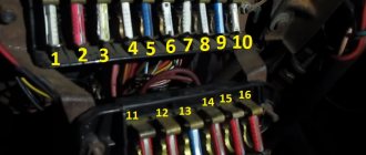
Replacing piston rings on a VAZ 2109 begins with disconnecting the negative terminal of the battery. To provide access to the crankshaft from the pit, remove the lower crankcase cover. There is a gasket at the junction, it will need to be replaced with a new one. Using a 10mm wrench, detach the oil receiver from the main shaft cover and the oil pump housing.
Next, we detach the exhaust pipe from the bracket under the bottom. Since the bracket is also attached to the body, unscrew the fastening bolts. We bend the ends of the locking plates of the nuts that secure the exhaust pipe and the intake manifold. We unscrew these nuts, as well as the nuts on the clamp, and remove the clamp. Next, the receiving pipe and the resonator pipe must be unfastened. Access is open from below; all that remains is to unscrew the nuts of the connecting rod screws and remove the connecting rod caps so that the connecting rod can be knocked out from below.
We move under the hood. After unscrewing the nut and washer that secure the air purification filter, and unfastening the 4 clips, remove the filter cover. We take out the filter element and its housing. Then you need to disconnect the air intake hose and the pipe on the valve cover. To remove the valve covers, it is necessary to unscrew the nut securing the accelerator drive cable.
Next, remove the front timing drive cover, loosen the tension roller and tighten the belt. You can dismantle the camshaft pulley by prying it up with a screwdriver. Now your goal is to bend the rear cover away from the cylinder head so that the cylinder head comes out from under the end of the camshaft. To do this, unscrew the fastenings of the cover and water pump.
We take out the tips of the high-voltage wire of the spark plugs, disconnect the wire block from the distributor. By unscrewing two screws we remove the distributor cover with wires. To completely remove the distributor, disconnect the interfering hose from the vacuum corrector, unscrew the nuts, and remove the bracket. Then disconnect the fuel pump and carburetor hose and remove the fuel pump. Next, disconnect the thermostat hose clamps and dismantle this device.
To unscrew 10 cylinder head bolts, use a 10mm hexagon. After pulling out the bolts and washers, finally disconnect the cylinder head. We remove the sealing gasket and always replace it. We clean the upper surface of the cylinder block from oil, dirt deposits and traces of the gasket.
We move into the pit. And, lightly tapping with a hammer, remove the piston assembly with connecting rod from the cylinder. We repeat the procedure with the three remaining pistons.
Step-by-step replacement instructions
Piston repair work must be performed on an inspection ditch, lift or overpass.
What will you need?
To repair a VAZ 2109 engine with your own hands, you need the following tools:
- a set of keys;
- set of heads;
- funnels;
- extension cords;
- torque wrench;
- set of probes;
Set of gap gauges - mandrel for pressing products on the piston;
- hammer;
- needle file;
- new repair kit.
New consumables for piston VAZ 2109
When purchasing piston rings for the VAZ 2109, you should take into account the material of manufacture and their width. It is better to purchase original products to avoid fakes.
Correct installation of piston rings
Sooner or later, your engine will wear out and will require either a replacement of the piston rings or the piston as a whole.
It seems that changing piston rings is an ordinary task, accessible to anyone who is more or less familiar with the structure and operating principle of a primitive four-stroke engine. But, unfortunately, people are afraid to spend 15 minutes of their incredibly precious time reading literature and stuff everything into the engine according to the principle (and that’s how it was. It’ll probably work). Well, the flag is in your hands and contact the service as soon as possible.
So, we take the piston and see 3 grooves for installing piston rings. There are no limit stops on 4-stroke engines, like on 2-stroke engines, for example.
There are two types of piston rings on 4-stroke engines. The first two, which are installed in the two upper grooves, are compression. Even from the name it is clear that they are responsible for the presence of compression in your engine and must retain the gases formed at the moment of the outbreak due to the combustion of fuel in the combustion chamber.
The next three rings are oil scraper rings. Here, too, their purpose is immediately clear. They are responsible for skimming off the oil that coats the cylinder walls as the piston returns down. If these rings leak, then the oil will remain on the cylinder walls, and this can lead to the fact that the engine will begin to consume oil, and, naturally, smoke will appear.
How to install first? Yes, in principle, as they were from the factory, in the same order, but to avoid mistakes we show them again.
Initially, we install the main oil scraper ring: the one that has a wave-like structure. Installing it could not be easier, since it is the most elastic of all.
Next, install the upper and lower THIN oil scraper rings. They are a little harder, but there shouldn't be any problems installing them either.
Now we install the piston compression rings: those that are thicker and “harder”. First install the lower one, then the upper one. They are a little more difficult to place as they are less elastic and harder. You are unlikely to be able to break them, but with completely crooked hands, bending them couldn’t be easier.
Do you think that's all? No!
The fact is that the rings still need to be correctly positioned on the piston so that the ring locks (the cut location) do not fall on each other. Simply put, it is necessary that the cut of the lower ring is not located directly above the cut of the upper ring.
We start with the upper piston rings.
We place the lock of the lower ring in the middle above the cavity of a valve, for example, an intake valve (it can also be an exhaust valve, there is no difference).
We place the lock of the upper ring strictly on the opposite side from the lower ring. Accordingly, if the lock of the lower ring is above the cavity under the intake valve, then the lock of the upper ring is above the cavity under the exhaust valve.
Now let's move on to the oil scraper rings. These rings need to be positioned in exactly the same way so that no lock matches. Therefore, we place the upper ring above the hole for the piston pin, on the right side.
We place the second one (the one at the bottom) on the opposite side, also approximately in the middle of the hole for the piston pin.
We place the last wave-shaped oil scraper ring in any of the four resulting sections between the hole for the finger and the cavity for the valve.
And now to your question: what kind of nonsense is the author telling us here? And why so painstakingly set the position of all 5 rings?
Let's explain. We did all this so that it would not happen that when one lock was located above the other, gases would not pass through these locks (in the case of piston rings) and oil would not remain on the walls (in the case of oil scraper rings).
If we take into account the piston rings, then this is a loss of compression and the passage of hot working gases to the oil scraper rings, which are not designed for such suddenly high operating temperatures. As a result, the rings may burn out after a certain time. If we turn to the oil scraper rings and the coincidence of the locks on them, then the oil will not be completely removed: it will reach the piston rings, which will lead to coking of the ring grooves, and as a result they will settle and then burn
If we turn to the oil scraper rings and the coincidence of the locks on them, then the oil will not be completely removed: it will reach the piston rings, which will lead to coking of the ring grooves, and as a result they will settle and then burn.
As a result, you will get burnt rings and piston wear.
Bottom line: adjusting the ring locks before installation is a matter of 2 minutes, and this operation can extend the service life of the motor by tens of hours.
Purchased larger piston rings
If you accidentally bought larger piston rings (for example, the cylinders were bored out for the first repair, but the seller made a mistake and gave piston rings for the second repair), naturally these rings will not fit into the cylinder.
First, you can exchange them with the seller who sold you the rings.
Second, you can carefully sharpen the edges to size.
Third, you can make a lock on these rings, but you must be good at using a file and this work requires patience and perseverance, I made such locks on piston rings, the compression increases and the engine pulls better.
Rice. Homemade locks on the piston ring
If you decide to make locks on the rings, then do them like this: insert the ring into the cylinder so that the ends of the rings overlap each other, draw a line along the upper edge of the ring with an awl, this will let you know how far the edge of the ring extends. Next, use a file to make the locks in the rings as shown in the figure, check the locks on the rings like this, measure the height of the ring with a caliper, divide by two, this will be the size of the height of the lock, after be sure to check that the locks in the piston do not jam, put the ring on the piston and crimp the ring with your fingers so that the locks are engaged, if the locks fit tightly, then sharpen the height of the locks a little more, the locks should overlap each other freely.
The piston rings are on, unscrew the cushion from the connecting rod (it is advisable to immediately replace the old bearings with new ones, but the size is written on the bearings, buy the same size of bearings). Insert the liner into the connecting rod so that the liner lock fits into the slot of the connecting rod bed, lubricate the liner and piston rings with machine oil. The insert is shown by an arrow.
We begin to insert the piston into the first cylinder, turn the crankshaft journal down, and insert the piston into the cylinder so that the arrow on the piston points to the front, as in the photo
Next, you need to carefully insert the piston rings into the cylinder, and I use a homemade crimp made from the return spring from the kickstarter of the Voskhod motorcycle. You can make a crimp yourself from such a spring or from another metal, as long as the metal is not soft and does not bend when crimping the ring. In the photo on the piston there is my crimp, why I like it, I carefully insert one ring at a time, and with the factory one you hammer in all the rings at once, but you have to hit the factory crimp with the handle of a hammer and I know many cases when the rings were not crimped very tightly with the factory clamp and the rings broke. And when you insert one ring at a time, you can easily drive it in with your palm or the edge of your fist, and if you press the ring poorly, it won’t fit and you won’t break it with your hand. By inserting the piston rings one at a time, I am one hundred percent sure that all the rings are intact.
We begin to insert the piston into the cylinder, the oil scraper ring is rigid and therefore squeeze the crimp with pliers and drive the piston in by hand, as shown in the photo.
The rest of the rings are soft and can be pressed with your fingers as shown in the photo, but these are German rings, VAZ ones are tougher, and if you don’t have enough strength to squeeze the ring with your fingers, use pliers.
The piston is inserted into the cylinder, push it with a piece of wood to the very bottom so that the connecting rod rests on the crankshaft, be sure to look from the bottom at how the connecting rod has become and whether the liner has come out of the connecting rod bed; if the liner has shifted slightly, push the connecting rod up and straighten the liner. Start tightening the connecting rod cushion, it is important to always wipe the place (connecting rod bed) where the liner is placed with a rag before placing the liner.
Very important. The connecting rod cushion is screwed in such a way that the locks of the bearings must be together (the lock of the connecting rod bearing must rest against the lock of the bearing bearing). Therefore, be careful and insert the connecting rod bearing correctly, tighten the connecting rod bearing, rotate the crankshaft, if it turns easily, then everything is correct, if it is very tight or does not fit, then the bearing was installed incorrectly, or the liner came out of the groove with a lock and was jammed, or the liner is the wrong size Be careful when changing the liners, the size of the liner should be exactly the same.
The pistons are all installed, now you need to screw on the oil receiver. Be sure to apply sealant to the tip of the oil receiver tube as shown in the photo. If this is not done and the worn sealing ring allows air to pass through, then there will be low oil pressure and the engine will knock, there is no need to buy a new sealing ring, the sealant holds perfectly.
Once you have screwed on the oil receiver, screw the pan so that the pan gasket does not fly off; it can be tied with simple threads in several places, the threads do not interfere, and installation of the pan is simplified.
The pallet is installed, we begin to clean the block from pieces of stuck gasket (this operation can be done at any time) as shown in the photo, you can clean it with a knife or a wide screwdriver, but do it carefully, try not to scratch the block too much. The block must be perfectly clean; if small pieces of the old gasket remain, a gap will appear in these places and antifreeze will flow either into the cylinder or out. If pieces of the cleaned gasket get into the cylinder, clean the cylinder, rotate the piston up and remove debris. Also clean the head.
Pay attention to the photo, you see the shells, these shells are the result of driving on A-76 gasoline, or due to very early ignition. It’s good if they become clogged with carbon deposits over time, but it may also be that this place gradually begins to deteriorate further and renders the head unusable.
Parts and consumables:
- Oil filter
- Engine oil
- Rags
Tools:
- Tubular socket wrench 13 mm
- Mandrel for pressing in piston pin
- Mandrel for compressing piston rings
- Hammer
- Piston ring puller
- Flat feeler gauge
- Torque wrench
Parts and consumables:
1. Insert the connecting rod into the piston so that the bosses on the connecting rod face toward the rear of the piston.
Note:
There is a mark in the form of a hole on the front part of the piston bottom.
3. Install the piston pin snap rings into the piston grooves.
4. Install the piston rings. It is recommended to do this with a special puller. If it is not there, install the rings on the piston, carefully opening the ring locks.
5. The order of installation of the rings is as follows: first install the composite oil scraper ring (the ring lock should be on the opposite side of the expansion spring lock), then the lower compression ring and, finally, the upper one.
6. Orient the rings as shown in the figure. Install the rings on the remaining pistons.
The location of the piston ring locks before installing the piston into the cylinder:
1 — oil scraper and upper compression ring expander;
2 - upper oil scraper ring;
3 - lower compression ring;
4 - lower oil scraper ring.
Note:
Install the lower compression ring with the marking facing up.
7. Install the liner into the connecting rod, aligning the installation tab of the liner with the notch on the connecting rod.
8. Lubricate the cylinder bore, piston, piston rings and connecting rod bearing with engine oil.
9. Install a mandrel on the piston to compress the rings and, screwing in the screw, compress the rings.
10. Rotate the crankshaft so that its connecting rod journal, on which the connecting rod and piston group is mounted, is installed at TDC. Install the cylinder piston according to the cylinder number marking on the connecting rod.
11. Press (for example, with the handle of a hammer) on the piston and slide it from the mandrel into the cylinder until the lower connecting rod head is installed on the crankpin of the crankshaft. Install the pistons in the remaining cylinders in the same way.
Note:
When installing pistons into cylinders, the marks (holes) on the pistons must face the front of the engine.
Warning:
When installing the piston, press the piston ring compressor firmly against the cylinder block, otherwise the piston rings will be broken.
Install the piston into the cylinder carefully so that the lower head of the connecting rod does not damage the connecting rod journal of the crankshaft
12. Install the connecting rod bearings into the connecting rod caps, aligning the mounting tab of the bearing with the recess on the cap.
13. Lubricate the connecting rod bearings in the connecting rod caps and the crankpins of the crankshaft with engine oil.
14. Install the connecting rod cover by connecting the connecting rod to the crankshaft journal.
Warning:
Install the connecting rod cap so that the cylinder number markings on the connecting rod and on the cap are located on the same side.
15. Lubricate the threads of the connecting rod cap bolts and nuts with engine oil.
16. Screw on the connecting rod bolt nuts without fully tightening them.
17. Tighten the nuts of the connecting rod bolts to a torque of 13.7-15.7 Nm (1.4-1.6 kgf*m).
18. Tighten all nuts 35-40° clockwise.
19. Check the ease of movement of the connecting rods along the crankpins. If jamming occurs, unscrew the connecting rod bolt nuts and retighten them as described in paragraphs. 17.18.
20. Using a feeler gauge, check the side clearances between the connecting rods and the crankshaft cranks. The nominal gap is 0.200-0.470 mm, the maximum permissible is 0.5 mm. If the side clearance is greater than the maximum permissible, replace the connecting rod and/or crankshaft.
21. Install the removed parts in the reverse order of removal.
Running in the engine
After assembling the engine, it is recommended to run it on a stand. Since this cannot be done outside of special repair organizations, after installing the engine on the car, run it in a simplified cycle as follows:
1. Fill with oil and coolant, check the tightness of all connections.
2. Start the engine and let it run without load according to the following cycle:
- 820-900 rpm - 2 minutes;
- 1000 rpm - 3 minutes;
- 1500 rpm - 4 minutes;
- 2000 rpm - 5 minutes.
Do not bring the engine to maximum operating conditions.
3
During operation, check the tightness of the engine and its systems, oil pressure, pay attention to the presence of extraneous noise
4. If extraneous noise or other malfunctions are detected, stop the engine and eliminate their causes.
5. When you start using the car, follow the regimes provided for the break-in period of a new car.
The article is missing:
High-quality photos of repairs
Replacement process
Replacing the cylinder head gasket on a VAZ 2109 is a simple procedure and is similar for engines that have both a carburetor and an injector.
Required Tools
In order to change the gasket, the cylinder head must be removed, and the following tools may be required for removal and replacement:
- hexagon;
- a set of keys;
- set of heads;
- torque wrench;
- extension;
- gasket remover;
- flat screwdriver.
To perform this procedure, the vehicle must be placed on a suitable lifting device.
Stages
Replacement is carried out as follows:
- The vehicle's power is turned off by disconnecting the negative terminal from the battery.
- Next, you need to drain the working fluids. The coolant may not be completely drained. The oil is drained if antifreeze gets into it.
- Next, you should disconnect all the wires with the sensors, remove the thermostat, the air filter along with the pipes.
- Then the timing cover is removed and the muffler pipe is disconnected.
- Next, you need to set the alignment marks and remove the timing belt.
- After disconnecting all supply hoses, you need to dismantle the carburetor.
- Next, remove the cooling system pipes and the protective timing cover.
- After this, the mounting bolts are unscrewed and the cylinder head is dismantled.
Dismantling the cylinder head on a VAZ 2109
- If the old gasket has become stuck and is difficult to remove, you can use a special product.
- Before installing a new consumable, carefully inspect the surrounding surfaces. There should be no defects on them, otherwise the head should be ground.
- When the surfaces are ready for installation, they need to be cleaned of dirt, degreased, and a new part can be installed. It is installed along guides located in the corners. For better sealing, a layer of sealant is applied at the joint.
- The fastening bolts must be tightened with a torque wrench to the torque specified in the VAZ 2109 operating manual.
Bolt tightening diagram - After installing the cylinder head, you need to replace all the removed parts in the reverse order.
Sorry, there are no surveys available at this time.
Installation and removal of piston rings
Thoroughly clean the used piston to remove any adhering dirt.
Pay special attention to ensuring that the ring grooves are free of oil deposits and dirt. If necessary, clean the oil return holes using a drill or other suitable tool.
Be careful not to damage the side surfaces of the groove when removing oil deposits from them. At the lower lateral surface of the groove there is a sealing surface
During operation, damage due to scratches may lead to excessive oil consumption or increased leakage of gases from the combustion chamber into the engine crankcase.
To install and dismantle piston rings, be sure to use special pliers for their installation. Other aids, such as wire loops or screwdrivers, damage both the piston ring and the piston.
Never tighten the rings by hand (exception: oil control piston rings with steel plates). Not only is there a risk of the ring breaking, deforming and stretching, but there is also the risk of injury from the sharp edges of the ring if it breaks.
Quickly putting on the piston ring by hand without breaking it, however, proves the dexterity of the mechanic; however, the piston ring is damaged in most cases already during installation.
Rice. 3
Mounting kit for piston rings
Never tighten the rings onto the piston in the manner shown (Fig. 1). If the ring becomes warped and no longer lies flat in the groove, then it no longer rotates in that groove, is worn on only one side, or is not quite sealing enough. However, things get worse if the molybdenum layer comes off or breaks off the molybdenum coated rings. If loss of the sliding layer does not already occur during installation, this will happen at the latest during engine break-in. The sliding layer separates and damages the piston and cylinder surface. The piston becomes stuck in the cylinder bore because hot exhaust gases are forced between the piston and the cylinder wall. The detached particles damage the piston and working surfaces of the cylinder.
Avoid excessive removal and installation of piston rings. With each installation, the rings are slightly deformed. Do not remove the rings from previously assembled pistons again in order, for example, to measure them again. Follow the sequence of installation of the rings. First, the oil scraper piston ring is installed, then the second one, after which the first compression piston rings are installed.
Pay attention to the markings when installing. "Torus" means that this side should point upward towards the combustion chamber
If you are not sure whether there is a “Tor” marking, then insert the ring with the inscription at the top. “Tor” does not mean that we are talking about the first compression piston ring.
Rice. 2
Check to see if the rings can spin (rotate) freely in the ring grooves.
Check whether the ring completely disappears along the entire circumference in the ring groove, i.e., the working surface of the ring should not extend beyond the piston skirt
This is important because if there is insufficient clearance at the bottom of the groove (wrong ring or carbon deposits at the bottom of the groove), the operation of the ring is not guaranteed
When installing two-piece oil scraper piston rings, always pay attention to the position of the spiral spring expander (Fig. 6)
The ends of the expander should always be positioned opposite the piston ring joint.
Rice. 6
With three-piece rings, the correct position of the expansion spring is mandatory to perform the oil film removal function (Fig. 1 and 2). In any case, before installation, also check the position of the expansion spring on the piston with the rings already inserted. During transportation, the ends of the spring are in a relaxed state and may overlap each other. Both color markings on the ends of the spring must be visible (Fig. 3). If they are not visible, then the ends of the spring overlap and the ring does not function. All joints of the oil control piston ring, which consists of three parts (both steel plates and an expander spring), must be inserted offset by 120° relative to each other.
Move the piston ring joints of the piston ready for installation so that they lie approximately 120° in relation to each other. They help the piston and, accordingly, the rings when the engine is first started. Reason: when the engine is first started, the compression is slightly lower, since the piston rings have not yet broken in. By moving the butt ends relative to each other, it is possible to prevent too many gases from leaking from the combustion chamber into the crankcase when the engine is first started and, as a result, the engine is difficult to start.
Stages
- First of all, you need to dismantle the cylinder head with your own hands.
- Then you need to remove the engine oil pan.
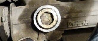
- After rotating the crankshaft, install it so that the connecting rod mounting nuts extend as far as possible.
- After unscrewing the fastening nuts, remove the connecting rod caps.
- Using a hammer, tapping lightly, remove the piston with connecting rod from the cylinder.
- Having opened the gap with your fingers, you need to remove all three products from the groove in turn and dismantle them from the piston. Together with the oil scraper, its expander is removed.
- Using old products, you should clean the grooves from carbon deposits.
- Removed products must be checked for suitability. To do this, they must be inserted into the cylinder and the gap measured using a feeler gauge. It should be in the range of 0.25 - 0.45 mm. A gap of up to 1 mm is allowed. If the value is greater, then the part must be urgently replaced. If the gap is larger, then the product needs to be sharpened using a needle file.
- Before installing new products on VAZ 2109 pistons, they should be run in the grooves. If biting is detected, the part must be ground in using fine-grained sandpaper.
The table shows the maximum values of the gaps between the part being replaced and the groove walls.
| Type of ring | Gap value, mm |
| Upper compression | 0,04 — 0,075 |
| Lower compression | 0,03 — 0,065 |
| Oil scraper | 0,02 — 0,055 |
- When installing, all parts should be thoroughly lubricated with oil.
- Installation of products begins with the oil scraper. First, the expander is installed - a special spring with a lock. Then the product itself is put on her. The expander lock and the oil scraper ring gap must be opposite each other.
- The lower compression ring has a groove and a tooth. When installed, they should be at the bottom of the part. On the upper surface there is usually an inscription “vas” or “tor”.
- The upper compression ring is installed in the same way - with the lettering facing up.
- The sequence of putting on the parts is as follows:
- first, the lock is released so that the part can easily fit onto the piston;
- then the lock itself starts;
- the remaining part is installed.
After installation on the piston, all parts need to be oriented. The installation axis of the piston pin should be 45 degrees with the lock of the upper compression ring. The lock of the next product should be at an angle of 180 degrees with respect to the previous one. Thus, the angle between the oil control valve and the upper compression valve will be 90 degrees. Then the pistons and rings are pressed out with a special mandrel and inserted into the cylinders from which they were removed. Next, we perform the reverse assembly with our own hands.
After replacement, the VAZ 2109 piston rings must be run-in. In this case, you should not load the engine, drive on roads with long ascents, and change gears correctly.
Video “Installing piston rings”
This video shows the process of installing piston parts: how to install and what to pay attention to.
If you find an error, please select a piece of text and press Ctrl+Enter.
Source
How to correctly install rings on the piston on a VAZ 2109
The fact that the car requires replacement of the piston rings, and not some other repair work, will be indicated by the engine itself. The signs of such a malfunction appear quite clearly, so it will be difficult not to notice them. But before we talk about the symptoms, you need to understand what the rings are and what role they play in the operation of the engine.
Piston rings are elastic, open elements that are installed in special grooves on the piston body. They are made of high-strength steel or cast iron, and covered with an alloying material on top. The alloy coating further increases strength and also reduces wear rates.
Typically, 3 rings are inserted into the piston: 2 compression rings (occupying the 2 upper grooves) and 1 oil scraper ring (the lower groove). The purpose of the compression rings is to prevent hot gases from breaking through along the piston into the engine crankcase. Oil scraper - removes excess oil from the cylinder mirror, preventing it from entering the combustion chamber. In addition, the rings reduce the temperature of the piston, transferring almost half of the heat from its surface to the cylinder walls.
When the piston rings no longer cope with the tasks assigned to them due to their wear, the car engine signals this by displaying the corresponding symptoms.
SIGNS OF PISTON RING WEAR
Blue or black smoke from the exhaust pipe indicates that wear has reached a critical stage. This indicates that excess oil entered the combustion chamber past the oil scraper ring and burned there along with the fuel. Black smoke coming out of the crankcase ventilation tube indicates that the compression rings, due to wear, allow gases to escape from the combustion chamber into its cavity.
Critical wear is accompanied by a decrease in compression (the ability to maintain pressure) in the engine cylinders. This means that some of the gases formed during the combustion of the fuel mixture, which was supposed to push the piston, broke into the crankcase without performing useful work. This is what will lead to a drop in pressure in the cylinder, therefore, the engine will lose some power. Increased oil consumption is observed.
Compression is checked with a special device - a compression meter. When the nominal pressure values are unknown (there are no operating instructions), it is first measured in a dry cylinder, then a little engine oil is poured through the spark plug hole, and the measurement is made again. If the compression increases, then the rings need to be replaced. Similar signs can be observed in the case of their “occurrence”.
“Sticking” occurs when carbon deposits formed in the piston grooves prevent the piston rings from springing, resulting in a decrease in the tightness of their contact with the cylinder surface.
This problem, if the case is not very advanced, can be corrected with the help of special fuel additives. For an engine with a carburetor system, you can try cleaning it with a carbon remover spray that is injected directly into the carburetor. If removing carbon deposits from the combustion chamber has no effect, then there is only one way out - replacing the piston rings and cleaning the grooves.
Running in the engine after replacement
After replacing only the rings, without touching the pistons and cylinders, it is necessary to carry out a break-in, since the newly installed piston rings must grind into the old piston group for a longer time. There is a process of erasing micron irregularities to ensure a tighter fit of the rubbing surfaces.
Violation of the speed limit during running-in leads to an increase in the friction force between the ground surfaces and an increase in temperature. As a result, the wear of engine components accelerates. Proper initial start-up of the engine after replacing the piston rings is of decisive importance. It must be performed according to the following rules:
- the battery must be fully charged;
- the oil must match the make of the car;
- After starting, observe the oil pressure indicator. If it lights up for more than 7 seconds, turn off the engine and look for the cause;
- at normal oil pressure, without increasing the speed, warm up the engine to 80-90 degrees;
- turn off the engine and wait until the temperature drops to 50 degrees, then start the engine again;
- wait until the temperature rises to 90 and turn off the engine again. Repeat this operation 10 times.
After this process, your engine is ready to break in after replacing the piston rings.
Recommendations for running in the engine after replacing piston rings:
- do not transport a lot of cargo or passengers at this time; the weight of the loaded vehicle should be no more than 50% of the permitted maximum weight;
- for the first thousand km, do not exceed the speed limit, keep no more than 80 km/h, for the second thousand, no more than 90;
- do not move in one gear for a long time;
- Do not pick up speed too quickly, do not linger at idle speed.
- Before each trip, make sure that you have the proper oil level; after 1 thousand km, change the oil and filter.
Upon completion of the break-in process after replacing the piston rings, it is necessary to rinse the engine with flushing fluid, change the oil and filter element. Tighten the cylinder head and crankcase mounts again.
Signs of piston wear
On average, a piston replacement on a VAZ 2109 is required every 150,000 km
The car owner should pay attention to warning signs that indicate the need to change the rings
- The car began to require more fuel.
- Compression measurements showed a value of less than 10 atmospheres.
- There is less engine oil.
- Replacing oil seals does not help eliminate oil leaks.
The VAZ 2109 piston group is a set consisting of a piston, piston rings mounted on it, a piston pin and its fasteners. There are three grooves on the surface of the piston for rings.
Two compression rings are responsible for the tightness of the space above the piston. They maintain normal compression and also prevent oil from entering the combustion chamber.
The oil scraper is responsible for removing excess oil from the cylinder walls, thereby reducing fuel consumption. Only a film a few microns thick is left inside the cylinder liner to lower the piston. Well, the pin, which is inserted transversely inside the piston cavity, attaches the connecting rod to the piston.
When is it time to change rings?
There are three piston rings on the VAZ 2109. They are not closed rims that are located on the outer wall of the cylinder in special grooves. These parts serve to seal the combustion chamber, regulate oil flow and improve heat transfer through the cylinder wall. Two compression valves prevent gases from the combustion chamber from entering the crankcase, and an oil scraper valve removes oil from the cylinder walls and prevents it from entering the combustion chamber.
Wear of piston group parts occurs after approximately 150 thousand kilometers due to the action of gases and friction of metal parts. They need to be changed if the following symptoms are present:
- compression drop;
- increased fuel consumption;
- the appearance of bluish smoke in the exhaust gases;
- increased oil consumption.
The cause of deterioration in engine performance may be coking of the piston and stuck rings. This happens when using low-quality fuels and lubricants that do not meet the manufacturers’ recommendations. During long-term operation, carbon deposits form, which covers the combustion chamber and its parts. Piston rings covered with carbon deposits “stick” and cannot perform their functions properly. In this case, they should be changed or decarbonized.
Coked piston with traces of carbon deposits
How to properly install piston rings on a 402 engine
Hello dear friends! Continuing with the engine overhaul, in this article we will deal with piston rings. Yes, we will devote a whole article to piston rings, because piston rings are one of the most important engine parts. Let's figure out what the wear of piston rings entails. The elasticity of piston compression rings, compressed by a steel tape to a gap in the joint of 0.4 mm, should be 17.5 - 25.0 N. With increasing wear, the correct geometric shape of the cylinder liners is disrupted, the gaps in the joints of the rings, the gaps between the rings and the annular grooves increase in the piston; The elasticity of the rings decreases greatly. All this leads to a violation of their sealing properties. As wear increases, the amount of gases penetrating the engine crankcase also increases, and oil consumption begins to increase.
But the main reason that determines the need to replace the pistons is wear of the grooves for the piston rings. The increased gap between the groove and the ring promotes intensive pumping of oil into the space above the piston. If the piston grooves are worn heavily, replacing the rings alone will not give positive results, therefore, if the gaps between the end of the ring and the groove in the piston are more than 0.15 mm, replace the pistons and rings with new ones. Pistons are replaced by selecting the liners (unless, of course, you are changing the entire piston group) in which they will work. Pistons are selected based on the force of pulling a probe tape 0.05 mm thick, 10 mm wide and 250 mm long between the piston and liner.
Selection of pistons by liners.
The feeler tape is placed between the liner and the piston on the side opposite the slot on the piston skirt along its entire length. The force when pulling the probe tape should be 35-45 N for new liners and pistons and 20-30 N for used liners and pistons. Pistons must be selected without piston pins at normal room temperature (+20 °C). If for some reason the selection has to be done at a temperature other than room temperature, then the tape pulling force should be closer to the upper limit at temperatures above 20 °C and closer to the lower limit at temperatures below 20 °C. After selection, the pistons are marked in accordance with the numbers of the cylinders to which they are selected.
If you install the entire piston group, a new one, then of course it will be easier. But still, I recommend that you place the piston and its sleeve as they were packaged. The piston rings will also need to be selected and checked. We install the rings one by one into the cylinder to a depth of 20–30 mm and measure the gaps with a feeler gauge. Compression rings should have a gap in the lock of 0.3-0.6 mm, oil scraper rings - 0.3-1.0 mm.
Checking the gap at the joints of the piston rings.
If you are installing a used piston group, then you must definitely measure with a bore gauge to see if the liners are worn out, according to the table. It will be necessary to check the gaps between the ends and the walls of the piston grooves using new piston rings. We check the gap at several points around the circumference of the piston. The side clearance for compression rings should be 0.050–0.082 mm, for the assembled oil scraper ring 0.135–0.335 mm.
We check the ring gaps in the piston grooves.
Now you will need to put all the rings in their places in the piston grooves. Usually on the packaging of piston rings, the manufacturer shows in what order to put on the piston rings. If it turns out that there are no instructions, then you will need to do the following:
- We put the rings on the piston, starting with the oil scraper ring;
- Having opened the lock of the oil scraper ring expander, install it in the lower groove of the ring, and then bring the ends of the expander together;
We put an oil scraper ring on the expander, the inscription to the bottom of the piston, the angle between the locks of the expander and the ring is 45 degrees;
We install the lower compression ring, with an inscription and a chamfer on the inside of the ring, also to the piston bottom;
Finally, install the upper compression ring.
You need to know that pistons of nominal and three repair sizes are produced for auto repair production. To ensure selection by liners, the pistons are sorted into five size groups, which are designated by letters of the Russian alphabet. The size group designation is stamped on the piston crown. The size groups of pistons of nominal and repair sizes, as well as their designations, are given in Table 1.
Table 1. Size groups of pistons of nominal and
repair sizes and their designations
Source
How to disassemble the piston of a VAZ 2109 car
If the piston engine on a VAZ 2109 car fails, it must be replaced in an inspection pit or overpass. To work with your own hands you need: a set of keys, a special torque wrench, a mandrel with which the rings are crimped on the piston. Replacing a piston VAZ 2109, the video shows in detail the procedure for performing the work. It is as follows:
- The battery, air filter for air purification, carburetor, ignition distribution sensor, and ventilation hose are pulled out.
- The lubricating fluid is drained from the engine sump.
- The sensor indicating the temperature of the cooling fluid is disconnected, the plug is unscrewed from the engine block and the antifreeze is drained.
- The “stove” is disconnected from the GB.
- The hose from the vacuum brake booster is removed from the intake manifold.
- The hoses are disconnected from the front pipes on the GB.
- The bolt holding the exhaust pipe to remove exhaust gases from the gearbox is unscrewed from the clamp, and the exhaust pipe is disconnected from the resonator pipe.
- The receiving pipe going to the manifold is disconnected from the engine.
- The upper and lower nuts securing the air intake are unscrewed. The latter also holds the front part of the shield, which protects the starter from the hot exhaust manifold.
Tip: You can simplify the removal and installation of the starter shield by removing the lower eye to secure it.
- The fasteners of the protective casing are unscrewed, it covers the camshaft drive belt.
- The belt tension is loosened. To do this, it is removed from the camshaft sprocket.
- The asterisk is removed.
- The back cover covering the belt is detached.
- The screws holding the head to the cylinder block are unscrewed.
- Having unscrewed all the bolts securing the cylinder head, the latter, after rocking, comes off from the cylinder head and is removed along with the gasket.
- The cover mounted on the clutch housing is released from the fastening and removed.
- The screws are unscrewed and the engine oil pan is removed.
- The oil receiver is pulled out from the pump housing to pump oil.
- The nuts of the connecting rod screws are unscrewed and the covers on the connecting rods are removed.
- With a light tap with the handle of a hammer, the piston with connecting rod and upper liner is pulled up.
Removing the piston and connecting rod from the cylinder
- In this way, all the engine pistons are pulled out.
- The connecting rod is clamped in a vice; the jaws on the vice are made of soft metal.
- Without applying much force, carefully use your fingers to open the locks on the piston rings, remove the compression rings, two in number, from the piston one by one.
- One oil scraper ring is removed.
- The oil scraper ring expander is pulled out.
Removing the Oil Ring Expander
How to change piston rings
Using old piston rings, the piston grooves are cleaned of carbon deposits. Before replacing the piston rings on a VAZ 2109, they need to be run in the piston grooves. If the rings bite, the parts must be ground in using fine-grain sandpaper. For convenience, it is placed on glass.
Tip: Pay special attention to the second compression ring. It is quite rigid, which means it is very fragile and can easily be broken.
You need to replace the VAZ 2109 piston rings after measuring the gap between the new piston ring and the groove wall with feeler gauges. The photo shows how this is done. There is a special instruction according to which the permissible gaps for rings in the piston grooves must be within the values specified in the table.
| Ring | The gap that should be between the piston ring and the groove wall located on the piston |
| Compression top ring | 0,04 — 0,075 |
| Compression bottom ring | 0,03 — 0,065 |
| Oil scraper ring | 0,02 — 0,055 |
- If the maximum permissible gap is exceeded, you will need to replace the piston rings on the VAZ 2109 yourself.
- The inscriptions “TOR” or “VAZ” should be at the top when installing the oil scraper and upper compression rings.
- The lower compression ring is oriented with the groove down.
- The rings are put on the piston in the following sequence:
- the ring lock is moved apart to such an extent that the ring can be easily placed on the piston;
- the ring lock is engaged on the piston;
- The rear part of the part is installed.
Installation of new rings on the piston begins from the oil scraper ring expander. After installation, the expander lock ring must be rotated 180 degrees relative to the ring lock. After installing all the rings on the piston, they must be oriented so that the angle between the compression top ring lock and the piston pin installation axis is 45 degrees. The lock on the lower compression ring rotates 180 degrees, and the angle between the lock on the oil scraper ring and the lock on the upper compression ring should be 90 degrees. So:
- If the ring installation technology is violated, the lubricating fluid can penetrate into the cylinder, which will lead to the formation of carbon deposits on the walls of the combustion chamber, smoke will come out of the muffler, and oil consumption will increase significantly. Rings can only be placed on the piston with special pliers or using a special device.
- When installing the unit, you need to lubricate the cylinder bore, rings and piston with high-quality motor oil.
- A mandrel is put on the piston, the rings are crimped with it, when self-installing the rings on the mandrel, you need to lightly tap the handle of a hammer.
- Inserts are installed in the bottom cover on the connecting rod. Before this, the beds in the connecting rod and in the cover for the liners are wiped dry.
- The crankshaft connecting rod journal and the surface inside the bearings are lubricated with high-quality engine oil.
- There is an arrow on the bottom of the piston, orienting it so that its direction is towards the crankshaft pulley, the piston is placed in the block sleeve.
- The piston must be recessed into the cylinder. The mandrel must be pressed against the block, and the bottom of the piston must be tapped with the handle of a hammer. At the same time, it is necessary to monitor the movement of the connecting rod towards the crankshaft journal.
- The cover is installed on the connecting rod, the nuts must be tightened with a torque of approximately 5 kgf/m.
How to break in a car after installing new piston rings:
- The car cannot be fully loaded.
- Change gears in a timely manner.
- Roads should not have long climbs.
- Constantly check the oil level.
- You can’t sit in traffic jams for a long time and accelerate sharply.
- The lubricating fluid and oil filter need to be changed after 1000 kilometers.
To make it more convenient to control the process of installing the rings on the piston, it must be securely secured in a vice, this makes it easier to work and does not require outside help. Having securely secured the piston in a vice, we proceed to installation. We take a set of piston rings and select the oil scraper. It is dressed first, as it stands lower than the rest. First, the oil ring spring is installed, then the ring itself is carefully installed on the piston. It is not recommended to squeeze the oil ring too much to prevent it from bursting.
How to measure compression in cylinders, in detail
If you are going to measure the compression in the engine of your car, you need to follow a few simple rules:
• The engine must be warm. • The fuel supply is turned off (you can turn off the fuel pump, injectors, or use any other method).
We recommend: Internal combustion engine
• It is necessary to unscrew all the spark plugs (selective removal of spark plugs, as at a service station, is unacceptable, since in this case the resistance increases and the speed decreases). • The battery must be fully charged.
Compression can be measured with either the throttle valve closed or open. Moreover, each option makes it possible to obtain your own results and identify certain faults. For example, when the damper is closed, some air will enter the cylinders, which will reduce compression (it will be approximately 0.6-0.8 MPa). The air leakage in this case is quite insignificant and is approximately equal to its entry into the cylinder. As a result, compression begins to “react” very sensitively to even the most minor leaks.
When measuring compression with the damper closed, the picture is somewhat different. The significant volume of air that enters the cylinder, of course, increases leakage. However, they are significantly less than the amount of incoming air. Therefore, compression drops slightly (to 0.8-0.9). Thus, measuring compression with the valve open is best suited for identifying significant engine damage, for example: damaged pistons, stuck rings, burnt valves, damaged cylinder bores.
Regardless of which of the two methods described above is used to check compression, during the measurement process it is necessary to take into account exactly how the pressure gauge readings change. For example, if on the first stroke the indicators are 0.3-0.4 and increase sharply on subsequent strokes, then this may indicate possible wear of the piston rings.
how to check engine compression
The most popular device for measuring engine compression is a compression meter. Its design is quite simple: a pressure gauge for measuring compression, a flexible hose, and an air inlet valve, which is inserted into the spark plug hole.
Well-known Western versions of compression meters, equipped with a whole arsenal of adapters, with which you can measure compression on cars of any brand.
You can also measure engine compression very quickly and accurately using a modern engine tester.
In fact, this device does not record the pressure itself, but the amplitude of the electricity that is used by the starter. It's simple: the higher the pressure, the more difficult it is for the starter to work, therefore, more energy is consumed. Using this device, you can measure compression in all cylinders simultaneously without removing the spark plugs, which is very convenient when working with multi-cylinder engines.
The main disadvantage of the motor tester is that the measurement results are displayed relatively - for example, as a percentage of the cylinder that works better. Only the most expensive models of engine testers show the compression value in each cylinder, and even then this is only possible if there is a large amount of data about the engine model, which is compared with the tester’s indicators.
what compression is considered normal?
With a fully functional engine, the indicators will be as follows:
Open damper: 1.0-1.2 MPa. Closed damper: 0.6-0.8 MPa.
When measuring compression, the main thing to remember is that the results obtained are relative, which means that you need to start not from specific numbers, but from the difference in compression in different cylinders.