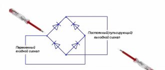
Once it starts working, the generator begins to produce direct current, but to operate all the devices in the car, as well as to charge the battery, an alternating current is needed (pulsating with a clearly defined frequency).
For your information! if the diode bridge stops working, the red battery icon lights up on the instrument panel, which informs the driver that there is no charging. We wrote in more detail about the reasons for including this information icon on this page.
It is the current conversion that the diode bridge of the VAZ 2110-2112 generator, which is also called a rectifier, is engaged in. And although there are many design options, the cars are equipped with three-phase ones, the advantages of which are obvious:
- At the output they create the smallest ripple voltage;
- Three-phase rectifiers are suitable for bridge and half-bridge diodes;
- They make it possible to install an additional capacitor - a current filter.
How to determine the health of the generator
Information about the operating status of the main unit responsible for generating electrical energy in the car is displayed on the dashboard for the convenience of motorists. The icon on the instrument panel that resembles a battery should go out after starting the vehicle’s power unit. This means that the power to the main electrical components has been switched from the battery to the generator. If the indicator does not go out, this indicates a breakdown in the electrical circuit. Problems may also be indicated by insufficient battery charge due to the lack of normal current rating.
Choosing a new generator
Despite the similarity of generators produced by different manufacturers, it is necessary to take into account a number of important factors. The main arguments are the number of consumers, generation, and vehicle equipment. You should pay attention to the trade article, rated power, and originality of the product. It is more logical to provide a power reserve. Any device that does not operate at maximum loads will live longer. We should not forget about the wire cross-section and battery capacity. An increase in power entails an increase in current loads and overheating of the wiring. When choosing a new generator, you have to search for the golden mean. If energy consumption has not increased, additional consumers have not been connected, it is more correct to look for an analogue of the factory generator according to the article number.
Manufacturing and installation of a diode in a VAZ-2114 generator
Now that everything is ready, we install an additional diode, more powerful than the previous one. You will need half a meter of wire 2*0.75mm. We solder the ends to the female and male terminals No. 4. We dress them in cambric, or better yet, in heat shrink. By the way, the old one must be removed from the system. Let's take action:
- Now, solder the following circuit to the diode: mother to the cathode, folder to the anode.
- We insulate the diode. For example, we take a film container.
- We remove the “minus terminal” from the battery.
- We unscrew the “+” wires from the generator, disconnect the “D” wire to the tidy.
- Remove the generator cover.
- Through the slots in the cover, we connect the “mother” to the LV, the “father” to the standard wire.
- We carry out the assembly.
Now, everything is ready for the final check and measurements.
Generators for VAZ 2106 and 2107
The generator on the VAZ 2106-2107 costs the same as on the VAZ 2101 - G221. If you install additional external current consumers that operate constantly, this will lead to undercharging and insufficient current will be supplied from the relay regulator. These additional devices include:
- powerful audio systems;
- fog lights;
- TV;
- preheater;
- additional heater;
- fridge.
Any similar device will lead to greater power consumption and, consequently, to premature battery discharge, even when the engine is running at high speeds. Standard devices for 2106 were developed a long time ago and are not designed for modern energy-consuming add-ons.
In this case, it is recommended to replace the standard generator with a more powerful unit.
G 222
If you need to increase the current power, then, when deciding which generator is better to install on the VAZ 2106 or 2107, instead of the standard one, take the G 222, which was installed on the VAZ 2105, Nivakh. It would seem that it itself is no better than the standard one on the “six”, but you can take an upgraded version that will be more powerful. Unlike the 221, this unit is designed with a built-in regulator relay, assembled into one unit with brushes. The G 221 gives an output of 42 A, and the 222nd - 50 A. Increasing the cross-section on the rotor winding increases the power, although the design is completely similar to the G 221. However, to install it on the 2106 you will need minor modifications. The easiest way is to install brushes from G 221. They fit perfectly in place of the relay. This modification is quite feasible even for car enthusiasts who do not have the skill.
It can be installed on a VAZ 2106 G222 with a standard regulator, but then it is necessary to change the connection diagram of the electrical machine.
On 2107 everything is installed without problems.
Check the voltage at medium engine speeds at the battery terminals, if it is 14 V at 2500 rpm, then everything is fine. You can drive with a more powerful unit by connecting additional options.
Generator 2108
This installation has greater efficiency, delivering a current of 55 A. It is installed on both 2106 and 2107.
The mount is identical to the standard ones, there are no problems during installation. Just remember to remove the battery terminal. You'll have to tinker with the connection to 2106. There are 4 wires going to the standard device. On the “eight” - three, since the voltage relay is built-in. To get a good result, insulate the black wire, connect the rest according to the standard system. The light bulb - the discharge indicator will light up when the generator is running, and will go out if there is no charging.
It is useful to make some more minor modifications. Instead of the old relay, install a regular power one. Then the light comes on only when the engine starts and at low speeds.
On 2107 you only need to add a power relay.
2107-3701010
An even more powerful installation is from the VAZ 2107i, producing 80 A, which can also be installed on the VAZ 2106–2107. With such equipment it is possible to install any electrical systems. For VAZ 2106 only 2107-3701010 is suitable; You can use any generator of this series for the carburetor “seven”.
When installing this equipment on 2106, it is better to modify it: replace the relay regulator with a similar one from G 222.
How to check a generator diode bridge
Test the unit on an installed or removed generator. To carry out the procedure, you will need wires and an ohmmeter, but an ordinary car light bulb will do.
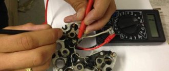
Checking the diode bridge on a car
Before testing, remove the negative terminal from the battery and disconnect the wires from the generator. If you are using a multimeter, set it to ohmmeter mode. Touch the positive red probe to terminal “30” of the generator, and the negative probe to the metal body of the generator. If the rectifier unit is working properly, the device readings will show an infinitely high resistance. Otherwise, the diode bridge must be replaced.
The above test allows you to determine the integrity of the bridge in terms of the absence of a short circuit. At the next stage, the element is checked for breakdown. Using the red positive probe, touch terminal “30” of the generator again, and the negative probe, in turn, touch the axle mounting bolts (usually they are square). The resistance must be infinitely large. Now swap the probes: the readings should be 500-700 Ohms. You need to check each diode separately, changing the polarity of the tester!
If you don't have a meter, use a 12V car light bulb. Then disconnect all the terminals from the battery and the wires from the generator. First you need to test the entire bridge:
- connect the minus battery to the metal housing of the generator;
- take a suitable wire and connect a light bulb (in series) to its gap;
- connect the other end of the wire from it to terminal “30” of the generator;
- the glow of the lamp indicates a bridge malfunction.
Next you need to test each diode. To do this, attach the minus to the housing, and touch the diode mounting bolt with the plus through the lamp. Its glow indicates a breakdown of the electronic component. Check each of them. Next, attach the “plus” coming from the battery to terminal “30” of the generator, and touch the diodes with the minus one by one. If the lamp lights up in any case, the bridge needs to be replaced. If you need to check additional diodes, leave the “plus” on terminal “30”, and connect the minus to terminal “61”: a glowing light indicates problems in the rectifier unit.
Checking the dismantled rectifier unit
Remove the generator and remove the bridge from it. Further course of action:
- set the tester to the ohmmeter position and turn on (if available) the sound indication;
- connect the negative probe of the device to the central plate, and touch the positive probe to a metal core (this can be a flat strip of metal or a bare wire);
- the device will show either infinity or 500-700 Ohms;
- swap the poles of the probes: the readings should change to the opposite;
- if the readings match, the diode is faulty;
- Do this procedure for each electronic component of the bridge.
Checking the removed bridge using a lamp
There is an opinion among some car enthusiasts that it is better to test the rectifier unit under load, using a 21W car lamp. To do this, you will need a battery and wires to create a simple electrical circuit, in which one wire is connected to the negative of the battery, the second - through the lamp (in series) to the positive. Check procedure:
- First, you should check the rectifier unit for short circuits between the plates. To do this, press the positive wire (its free end) to the top plate, and the negative wire to the bottom plate. The absence of a glow indicates that there is no short circuit. If you change the polarity of the connection, the lamp will light up.
- Now the positive elements are checked for breakdown and breakage. Press the positive wire with a crocodile to the top plate, the negative wire to each connection point of the diodes. In this case, you need to change the polarity: if the element is working, in one case the lamp will light, in the other - not.
- We do the same with the negative group of elements. But only here we attach the negative wire to the bottom plate.
- It remains to check the additional diodes. To do this, attach the positive wire to pin “61”, and the negative wire in turn to each connection point of the electronic components. Change the polarity and make sure that in one case the lamp lights up, in the other - not. If so, the diodes are good.
Check Features
contacts To carry out a comprehensive check of the diode bridge, two tools are enough - a digital combined instrument (multimeter) and a light bulb with a rated voltage of 12 Volts. It is possible to do all the work yourself, without the involvement of expensive craftsmen. To gain access to the assembly, remove the protective housing, and then disconnect the regulator output. In this case, take into account the color characteristics of the diodes:
- Red rectifiers are “plus”.
- Black rectifiers are a minus.
There are two ways to check the integrity of diodes on a VAZ. For greater reliability, it is recommended to use them in combination.
First, let's look at how to test a diode bridge with a multimeter. This option takes the least time and is most in demand among car owners. The algorithm is as follows:
- Remove the rectifier group from the generator. Unfortunately, it will not be possible to perform the test without removing the device from the car. This is because each diode must be tested individually. If they are “in the circuit,” it is unlikely that it will be possible to accurately diagnose the breakdown.
- Switch the digital device switch to dialing mode. After this, connect the probes to each other - you will hear a squeak from the special speaker of the device. If you are using a simple device that does not provide this option, move the switch to the “1 kOhm” position.
- “Sit down” with probes to the input and output of the diode, and then record the indicator. Next, do the reverse measurement. The rectifier can be considered intact if one measurement shows infinity, and another shows 0.5-0.7 MOhm. In the case when in both cases the minimum resistance is displayed on the device, or it shows infinity in the first and second options, this indicates a malfunction of one (group) of diodes.
Now let's look at how to check a diode bridge with a light bulb? This option is good when you don’t have a multimeter at hand. The role of the “device” in this case is played by a 12-volt light bulb.
The algorithm is like this:
- Connect the negative terminal of the battery to the diode bridge. At the same time, make sure that the plate is in close contact with the outer part of the generator.
- Check each diode individually. Take one terminal of the lamp and connect it to the “minus” of the generator, and the second to the “plus” terminal number “thirty” (from the battery). If the light comes on, this indicates problems with one or more diodes. In addition, the glow often indicates the presence of a short circuit in the circuit.
- Check the negative diodes. To do this, connect the negative light bulb to the generator casing, and the other wire to the mounting bolt on the bridge. If during such a check the lamp blinks or glows, there are problems with the “minus” group.
- Check the positive diodes. To do this, place the positive terminal on the “thirtieth” terminal, and the negative terminal on the mounting bolt. There should be no glow from the lamp. If such a problem occurs, there are failures in one or more “positive” diodes.
- Check the additional rectifier group. Take the negative edge and leave it in its original position, and apply the positive end to the sixty-one terminal. The glow of the light indicates a problem.
If checking the diode bridge shows a malfunction, take the broken diode and replace it with a new (serviceable) part. The optimal and simpler option is to purchase the entire diode bridge as a set, but in this case you will have to spend more money.
If you follow the recommendations mentioned above, diagnosing a fault takes no more than 1-2 hours. So don’t rush to the service station - do the work yourself. This way you can gain experience and save your personal budget.
Signs of a diode bridge malfunction
First of all, you need to remember that the diode bridge on the VAZ-2114 is no different from the same unit on the VAZ-2109, VAZ-2110 and other models. Therefore, if you figure out how to determine the malfunction, it will not be difficult to identify it on any of the cars. There are several main symptoms; they can appear together or separately. Any of them requires an immediate check of the generator:
- The warning lamp, which lights up when the ignition is turned on, does not go out even after the engine is started. This is a general indicator of a problem, but if the diode bridge has failed, the lamp will light in any case. If a voltmeter is installed in the car, you can check its readings; the arrow will most likely be either in the red zone or at its very border.
- Another option is that the warning light does not light up when you turn the ignition key and does not light up after starting the engine.
- When measuring the voltage produced by the generator with the engine running, the reading is less than 13.5 Volts. You need to measure at the battery terminals.
- The next morning the car will not start due to a dead battery, although in the evening it was in normal condition. After charging the battery, it discharged again in a short time, and the generator housing becomes so hot that you can burn your hand on its surface.
- Extraneous noise appears under the hood, most often it is a whistle or howl. The noise level may vary depending on engine speed.
- Various errors appear - the ABS, ESP, and so on may light up. The power steering may stop working, the radio will begin to wheeze and freeze. Instead of a turn signal, the light turns on. All this manifests itself against the background of a dead battery, which does not charge due to a broken diode bridge.
- The headlights begin to dim or stop working altogether, and the air conditioner does not cool as it should.
These are the main signs of a diode bridge breakdown, but it is worth remembering that they may indicate other generator failures. Therefore, first of all, you need to accurately identify the faulty unit. It is not necessary to take the car to a service center for diagnostics; the car owner can do the work; a minimum set of tools is needed.
Advice!
If the control light on the panel lights up or, conversely, does not work, first of all you need to check it and the control relay. Often it is these elements that are faulty, and not the generator.
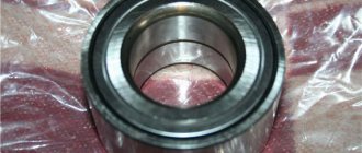
BEARINGS
The generator on a VAZ 2114 car consists of the following main parts:
- A housing consisting of two aluminum covers (front and back);
- Stator (winding located inside the housing);
- A rotor rotating inside the stator;
- Diode bridge;
- Voltage regulator.
The armature (rotor) rotates in two bearings, which are installed: one in the front cover and one pressed onto the rotor. Both bearings are press-fit and therefore are not that easy to replace.
There are usually two main problems with a generator:
- Charging disappears;
- Noise occurs: whistling, grinding or humming.
If there is a whistling noise under the hood, a worn alternator bearing is often to blame. Due to such a malfunction, charging is not lost, but you still shouldn’t drive with noise, since as a result the generator will jam because the rotor will stop rotating.
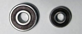
Before changing or starting repairs, you need to buy the necessary spare parts. And before purchasing, you need to find out what bearings are on the VAZ 2114 generator. A bearing of brand 180202 (a foreign analogue of 6202-2RS) is installed on the rear of the rotor, and 180302 (an analogue of 6302-2RS) is installed on the front cover. The cost of Russian parts is low - in the range of 50-80 rubles per piece, imported spare parts are noticeably more expensive - from 200-250 rubles. Bearings are often sold as a set, that is, in pairs. Imported analogues are of much higher quality, so when choosing parts it is better to buy brand 6202-2RS and 6302-2RS.
Bearing 6302-2RS
Checking the diode bridge of the VAZ generator
| One of the reasons for a generator malfunction may be a burnt-out diode bridge (generator rectifier unit). In this case, the battery will not receive enough charge, or, on the contrary, will be overcharged. Let's look at several ways to check a diode bridge with your own hands. |
The generator rectifier diodes act as a one-way valve that allows current to flow in only one direction, thereby blocking the flow of electric current from the vehicle's on-board network to the stator windings.
| Thus, a healthy semiconductor diode conducts current in only one direction. If it does not conduct current or conducts current in both directions, then the diode is faulty. |
Diodes burn out due to moisture ingress, or from improperly lighting the car in winter (when you confuse plus with minus). Before starting work, remove the diode bridge of the generator.
Checking the generator rectifier unit with removal and disassembly
The generator diode bridge should be removed and the multimeter turned on in diode test mode. Checking the generator auxiliary diodes:
- We connect the probe of the positive terminal of the multimeter to the common bus of the auxiliary diodes (1), and the probe of the negative terminal to the terminal of the diode being tested (2). If the diode is working, then the device readings will tend to infinity;
- We swap the tester probes. If the diode is working properly, then the device readings will be several hundred ohms.
The other two additional diodes of the rectifier unit are checked in the same way; Checking the power diodes of the generator diode bridge:
- Connect the negative terminal probe of the device to the diode bridge plate into which the diode is pressed, and the positive terminal probe to the diode terminal. A working diode should not pass current, that is, the readings on the device should tend to infinity;
- We swap the tester probes. If the diode is working properly, then the ohmmeter should show a resistance of several hundred ohms.
We similarly check other power diodes of the generator rectifier unit.
Checking the generator diode bridge without removing it
Required:
- Remove the generator protective cover.
- Disconnect terminal “B” of the regulator from terminal “30” of the generator
- Disconnect the wire from terminal “B” of the voltage regulator.
- Lamp 1..5, 12V.
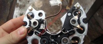
Three diodes with a red mark create a “plus” rectified voltage on the housing. They are “positive” and are pressed into one plate of the diode bridge connected to terminal “30” of the generator. The other three diodes with a black mark create a “minus” rectified voltage on the housing. They are “negative” and are pressed into another plate of the rectifier unit, connected to “ground”.
The diode bridge is checked in the order described below.
Checking positive and negative diodes for short circuits:
Connect the “plus” from the battery through the lamp to terminal “30” of the generator, and the “minus” to the generator housing. If the lamp is on, then the “negative” and “positive” diodes have a short circuit.
Checking negative diodes for short circuit:
We connect the “plus” of the battery through the lamp to one of the diode bridge mounting bolts, and the “minus” to the generator housing. If the lamp is on, it means there is a short circuit in one or more “negative” diodes (short circuit of the stator winding turns to the generator housing, or short circuit of the valves).
Checking positive diodes for short circuit:
Connect the “plus” of the battery through the lamp with clamp 30 of the generator, and the “minus” - with one of the mounting bolts of the rectifier unit. There is a short circuit of one or more positive diodes, which means the lamp will light.
Checking additional diodes for short circuit:
Connect the “plus” of the battery through the lamp to terminal “61” of the generator, and the “minus” to one of the diode bridge mounting bolts. If the lamp lights up, then there is a short circuit in one of the additional diodes. You can find a damaged diode only by removing the rectifier unit and checking each diode individually.
If a problem is found, then the generator diode bridge should be replaced. If it is working properly, then the causes of the disease may be in other elements of the generator.
| Have you ever had to check the generator diode bridge yourself? |
Photo source: Key words: xn--2111-43da1a8c.xn--p1ai
Video “How to avoid mistakes when replacing the DM in a VAZ 2110”
More clear instructions for replacing the diode bridge in the “Ten” with a description of the main points and nuances are given in the video below (the author of the video is Semyon Pedan).
Let's start with the fact that a diode bridge is an electrical circuit, a chain of diodes designed to convert alternating current into direct current. A faulty diode bridge is one of the main causes of generator malfunction, and is also a powerful consumer that can drain the battery to zero overnight.
A faulty diode bridge can both discharge and recharge the battery, which can result in major electrical problems. The principle of diodes, in addition to converting current from alternating to direct, is the unipolarity of current transmission from the generator to the battery. In other words, a working diode transmits current only in one direction (generator - battery), a faulty diode transmits current in both directions (battery - generator) or does not transmit anything at all. Diodes burn out due to poor contacts or moisture.
Before you start blaming the diode bridge for all your problems, be sure to check the generator brushes and voltage regulator.
To start checking the diode bridge, you need to remove it, fortunately the process is simple. You can also do without removing the rectifier block (diode bridge), but this is very, very inconvenient.
One way to check the diode bridge is to check the on-board system for current leakage (How to check for current leakage?)! If the current consumption in a stopped engine with electrical appliances turned off is 1A per hour or higher, then most likely the problem lies in the diode bridge. The bridge can only be checked more thoroughly when removed.
Description of the diode bridge on the “Ten”
How is the diode modified and installed in the device? For what reasons can a bridge fail? To begin with, we suggest that you familiarize yourself with the description of the part. If you dismantle the generator assembly from the car and remove the cover, you will be able to see the diode bridge (DM), which is located immediately behind it.
Purpose and functions
What functions does the DM perform:
- The primary task of the device is to convert alternating current into direct current.
- The DM also performs the function of blocking current from entering the stator winding. In this case, the device actually performs the one-way valve option.
- In addition, the DM is designed to increase the safety margin of the generator unit. It allows you to protect the mechanism from the effects of adverse factors and contamination on the device, and this, in turn, can negatively affect the functionality of the mechanism as a whole.
Device
As for the device, in the factory configuration the DM for the “tenth” generator is a monolithic structure. This design, as a rule, is quite strong and reliable, is characterized by its small size, as well as a relatively low price. The only drawback characteristic of factory-made DMs is that if one of the diode elements burns out, local replacement of the damage will not be possible. That is, the car owner will have to completely change the factory axle with his own hands.
As for the design features itself, the DM consists of:
- two aluminum plates;
- spacers made of plastic;
- as well as nine diodes, which are connected to each other by soldering into one structure, that is, a bridge.
DIY replacement instructions
In the event of a breakdown, the repair of the DM consists of its replacement, which is done as follows:
- First you need to turn off the ignition, open the hood and turn off the power to the on-board network; to do this, disconnect the battery.
- Once the battery terminal is reset, you will need to disconnect the pink cable responsible for activating the generator assembly. The wire itself is fixed with a bolt and nut; the nut itself will need to be unscrewed.
- Now you need to slightly loosen the tension on the top as well as the bottom nuts. Unscrew the tension screws and remove the strap. Inspect it - if the belt shows signs of damage - cracks, delamination - then it is better to change it immediately. If the strap is intact, set it aside.
- After completing these steps, you need to rotate the generator mechanism 90 degrees, this is done so that you can access the lower mounting screw. Unscrew it.
- Next, carefully inspect the body of the dismantled unit. If necessary, clean - there should be no dirt, especially on the connections. Dirt getting inside the generator housing can also lead to its incorrect operation and even failure. Bend the fasteners and remove the cover.
- Next, you need to clean the inside of the rings as carefully, but most effectively as possible.
- After this, all you have to do is dismantle the failed DM and replace it with a working part. When the installation is completed, the structure is assembled in the reverse order. Do not forget to tighten the strap, just make sure that it is not too tight, this is important. Having done this, you will need to start the engine of your car and diagnose the operation of the new DM.
Checking the diode bridge using a light bulb
Naturally, not every car owner has a multimeter, and therefore you need to know how to check the vehicle’s generator using improvised means? To do this you need two pieces of electrical wire and a car lamp. The check itself involves the following simple steps:
- The protective casing of the generator is removed and a diode bridge plate is connected to the negative terminal of the battery.
- The wire from one end of the light bulb is connected to the positive of the battery, and with the other you need to touch the terminals of the remaining diodes and the connection points of the starter winding in turn.
- If the lamp lights up at any terminal of the diode, it means that this element is faulty and needs to be replaced.
In some cases, it may be necessary to check the diode bridge for an open circuit, for which you need to carry out the following manipulations:
- The wire from the negative terminal of the light bulb is connected to the negative terminal of the battery and in the same sequence as checking for breakdown of the diodes, they are tested. The only thing is that in such a situation the light should be constantly on.
- If, during the test, the light on any of the diode terminals does not light up or its light is very dim, then the part has broken and will have to be replaced.
You can find out why malfunctions occur in the diode bridge of the generator yourself in a garage. In this case, you will need a regular tester, which almost every car enthusiast has, or a car light bulb with two wires.
Signs of a burnt diode bridge
The battery was fully charged the day before, you came to the garage - there was no charge, you charged the battery again, started the car, the battery was discharged after a few minutes, and the generator was so hot that it was impossible to touch it.
A terrible howl/whistle is heard from under the hood, which changes tone when the engine speed changes; the whistle can appear suddenly while driving.
During the trip, an ABSESP error appeared, which means there is a malfunction in the steering, the power steering stops working, the steering wheel turns hard, and the battery runs out.
The headlights dim while driving, the speakers turn off spontaneously, and the air conditioning stops working.
In order to confirm your opinion that it is the diode bridge that has failed, you need to check it. The following factors indicate a malfunction of the diode bridge:
· voltage at the generator output is less than 13.5 V;
· the signal indicator lights up when the engine starts;
· when testing the generator with a multimeter, the plus terminal “rings” along with the windings.
We made sure that the fault lies precisely in the diode bridge. Now we need to find and determine which diode has failed.
The best generators for VAZ
If the generator is seriously damaged, it does not have to be repaired, but completely replaced. Parts necessary for repair may be missing, or the breakdown may not be repairable at all. Meanwhile, the on-board voltage and the quality of battery charging depend on the good operation of the power unit. It's a shame when, despite a good motor, electrical equipment does not work properly.
And if we are talking about VAZ cars, then sometimes a replacement is in demand due to the lack of power of standard devices. Modern automakers offer many additional devices that increase the level of comfort when traveling, but they also consume a large amount of electricity, and old devices cannot cope, so they have to be replaced with more powerful ones.
Many people are interested: which generator to buy if they have a VAZ? Here you need to consider them separately by model, so before you go shopping, read the recommendations of specialists and compare them with your wishes and capabilities.
Replacing the alternator belt
The rubber ring used on the VAZ 2112 is available in two modifications.
The car model equipped with air conditioning has a larger diameter belt that rests on three pulleys. Motivation for installing a new belt:
- The warranty period ends, approximately 40 - 50 thousand kilometers;
- During the next maintenance, critical signs of product destruction (scuffs, tears, severe stretching, delamination) were discovered.
The procedure is carried out according to the method described above, with the exception of:
- there is no need to completely remove the bolts; it is enough to allow the generator unit to be tilted freely;
- no need to disconnect wires.
Tension the belt using the adjusting bolt. The normal value is considered to be a deflection of 1 - 1.5 cm when pressing the tape in the middle between the crankshaft and generator pulleys.
How to install an additional diode?
This is another way to modify the generator set to increase the battery charging voltage. This method is somewhat more complicated, since it will require complete disassembly of the generator. The modification consists of changing the connection of terminal D of the relay regulator.
The diagram in red indicates an additional diode that needs to be installed. 2D219B device is well suited for such a semiconductor device.
, but you can choose a similar one with similar parameters.
You need to find about half a meter more of two-core wire, two terminals “male” and “female” number 4, as well as a heat-shrinkable casing. At one end of the wire, terminals are soldered and insulated with heat shrink. The free ends of the wire must be soldered to the diode, the “mother” is soldered to the cathode, and the “male” is intended for the anode. Now you need to connect the “mother” to the RN
, and the standard wire is connected to the “male”. At this point the modification is completed, all that remains is to assemble the device, install it on the car and carry out tests.
As you can see, the alteration is not so difficult. Modification of the VAZ 2110 generator (installation of a diode) will allow fans of loud music and additional lighting effects not to think that the battery is not charging enough.
Modification of the relay regulator
For any modification of the generator set, you need to have at least a little knowledge in the field of electronics. To modify the “relay” for an increased battery charging voltage, you need to purchase the same relay from a foreign car with an output voltage of 14.5 volts, it is indicated on the top cover. The further order will be as follows:
- You need to disconnect the original “pill” from the domestic relay. You need to use a heated soldering iron and tweezers;
- The same procedure is carried out with imported “things”;
- After this, an imported relay must be installed on the domestic brush assembly. Here you will have to work hard, since the pins do not match and they need to be bent and soldered correctly;
- After this, it is securely fastened with screws to the body, having previously been treated with a special heat-shrink paste.
- That's it, you can install the relay regulator on the generator and test it in action, it should produce a voltage equal to 14.5 volts.
Possible malfunctions and their diagnosis
Generating equipment is exposed to a variety of adverse effects during operation.
The main negative factors causing generator failure:
- aggressive liquids, dirt, condensation;
- temperature changes, overheating,
- mechanical wear;
- transient processes in on-board wires, contributing to electrical breakdown;
- ugly, ill-conceived exploitation.
Some faults can only be fixed by a professional auto electrician. Most breakdowns are discovered on their own and repaired by an ordinary car owner with the correct hand anatomy.
External signs that draw the motorist's attention to unstable operation of the generator
- After starting the engine, unpleasant noises of various nature are heard in the engine compartment, and the smell of burnt rubber is felt.
- The instrument panel shows that the battery is discharged and is not charging well.
- There are difficulties starting the engine, the battery has been checked and charged.
- The light bulbs burn at full intensity, flicker, and change brightness depending on the crankshaft speed. The lighting of the panel and interior is dim.
- An external inspection reveals mechanical damage to the housing and generator elements.
Possible breakdowns
- insulation destruction, short circuit, winding wire breakage;
- overheating, belt rupture;
- leakage of lubricant, knocking, destruction, jamming of ball bearings;
- malfunction of electronic parts of the rectifier circuit, regulator.
Troubleshooting Methods
Two diagnostic methods are usually used:
- Visual control.
- Metrological testing.
The first option allows you to identify contamination, traces of mechanical and chemical influence. Exceeding the temperature regime is determined by physical contact. After turning off the ignition, you need to lift the hood and slowly move your hand towards the generator. The increased temperature will be felt at a minimum distance, before touching.
To implement the second activity, you need to equip yourself with a measuring device and acquire basic skills in measuring resistance, voltage, and current.
Checking the VAZ 2112 generator with a multimeter
A classic pointer tester, a modern electronic multimeter with a liquid crystal screen, is suitable as a testing device. Set the switch to the “DC voltage measurement” position, limit 0-30V.
- First step. The ignition is turned off. Battery voltage measurement. The norm is 12.5-12.7V.
- Second step. The engine is running at idle speed. Consumers are disabled. The measurement shows 13.8-14.5V.
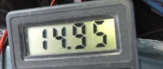
- Third step. Turn on the lights and music. Normal range is 13.7-14V. Pressing the gas pedal does not raise the voltage by 0.5V. A value exceeding 15V indicates a regulator failure. A faulty generator will not produce more than 13V.
Checking the diode bridge
The tester is in the “resistance measurement” position. The straightener consists of two parts. One clip contains three diodes with anode contacts on the body. The other is with cathode ones. The whole valve in the forward direction will show 0 ohms. The reverse resistance is 600 kOhm. An infinite value means a break; a zero value means the diode is broken.
Winding measurement
To check the field windings, you need to touch the slip rings with the probes of the device. The working value is from 1.8ohm to 5ohm. Readings outside the specified numbers indicate a malfunction.
The stator windings are checked in two modes - among themselves, for ground. In the first case, a value of several ohms is accepted as correct. In the second option, an infinitely large reading satisfies.
The following are practical tips for troubleshooting the most common generator equipment problems.
Brief description, principle of operation of the generator
Content
A car generator is an electrical machine that uses the mechanical energy of a power unit to generate electric current. Modern cars are equipped with alternating current electric generators.
The main task of the generator unit is to maintain the operating voltage of the vehicle's on-board network and charge the battery after starting the engine. Traditionally, the device is located in the front part of the engine compartment, driven by a belt drive from the crankshaft of the power unit.
Main components of the VAZ 2112 generator
The metal case, made of two covers, is tightened with long bolts and protects the windings from mechanical stress. The material chosen is aluminum alloy, which has all the necessary qualities: lightness, sufficient strength, immunity to magnetic fields, high heat transfer.
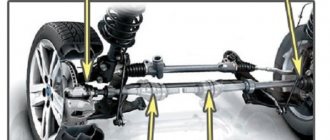
The main components of the VAZ 2112 generator: 1 – casing; 2 – output “B+” for connecting consumers; 3 – noise suppression capacitor 2.2 μF; 4 – common terminal of additional diodes (connected to the “D+” terminal of the voltage regulator); 5 – holder of positive diodes of the rectifier unit; 6 – holder of negative diodes of the rectifier unit; 7 – stator winding terminals; 8 – voltage regulator; 9 – brush holder; 10 – back cover; 11 – front cover; 12 – stator core; 13 – stator winding; 14 – spacer ring; 15 – washer; 16 – conical washer; 17 – pulley; 18 – nut; 19 – rotor shaft; 20 – front rotor shaft bearing; 21 – beak-shaped pole pieces of the rotor; 22 – rotor winding; 23 – bushing; 24 – tension screw; 25 – rear rotor bearing; 26 – bearing sleeve; 27 – slip rings; 28 – negative diode; 29 – positive diode; 30 – additional diode; 31 – pin “D” (common pin of additional diodes).
The stator is made up of tightly pressed metal plates to combat Foucault currents. The stator windings are located in thirty-six slots cut into the plates.
The rotor creates a rotating magnetic field. It consists of a core with windings of copper, varnished wires, rotates on closed, maintenance-free ball bearings. The shaft is fitted with copper rings connected to the excitation winding, a cooling fan impeller, and a V-shaped belt drive pulley.
The graphite brush assembly acts as a transmission link between the excitation winding and the battery, the self-excitation circuit.
A block of rectifier diodes, assembled according to Larionov’s circuit, converts three-phase voltage into constant power supply to the mains. A circuit of nine diodes is assembled on two metal frames used to dissipate heat during operation. Six main diodes power the on-board network. Additional semiconductor valves power the excitation winding after the generator reaches stable speeds and prevent the battery from discharging when the engine is stopped.
The voltage regulator controls the stability of the mains voltage at different engine speeds and performs temperature compensation of the battery charge depending on environmental parameters.
Algorithm for the operation of the VAZ 2112 generator
The driver turns the key in the ignition. A power circuit for the excitation winding is created from the battery. The starter rotates the crankshaft flywheel. At the same time, the generator rotor begins to rotate through the V-belt connection. The magnetic field created by the rotor current frames penetrates the stator windings. Induced electricity is generated. An alternating voltage appears at the output contacts of the device. During the time the engine is started by the starter, the generator manages to gain the required speed. The rotor winding is switched to power from a self-excitation circuit.
The rectifier module is responsible for creating direct current. The battery goes into charging mode. The voltage regulator maintains the parameters of the electrical network within specified limits.