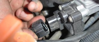
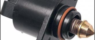
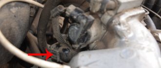
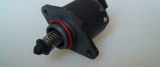
1. Release the clamp of the wiring harness block and disconnect the block from the idle speed control.
The terminals are marked on the idle air control block.
2. Connect the negative probe of the engine voltage.
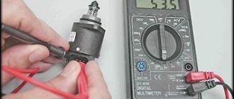
3. Having turned on the ignition on the VAZ car, use a voltmeter to measure the voltage at terminals A and D of the idle speed control block.
ATTENTION The voltage on the idle speed regulator block must be at least 12 V (the negative probe of the device must be connected to the engine ground). If the voltage does not reach the idle speed control block or it is less than 12 V, the battery is discharged, the power circuit is faulty, or the ECU is faulty.
4. After completing the voltage measurement, turn off the ignition on the VAZ-2104, VAZ 2105, VAZ 2107.
Removing the idle speed regulator from a VAZ-2104, VAZ 2105, VAZ 2107 car
1. Remove the throttle body.
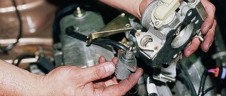
2. Using a Phillips screwdriver, unscrew the two screws securing the idle air control to the throttle body.
3. Remove the idle speed control. An O-ring is installed in the connection between the VAZ idle speed control and the throttle body. Replace a ring that has lost elasticity or is cracked.
4. Using an ohmmeter, we measure the resistance between the terminals of the windings of the idle speed control VAZ-2104, VAZ 2105, VAZ 2107.
The electrical resistance between terminals A-B and C-D should be within 52-53 Ohms. The resistance between terminals A-C and B-D should be high (tend to infinity). The faulty idle air regulator on a VAZ car needs to be replaced.
ATTENTION Before installing a new idle air regulator on a VAZ-2104, VAZ 2105, VAZ 2107, you must make sure that the valve needle protrudes no more than 23 mm.
5. Using a caliper, measure the protrusion of the needle of the new valve.
6. If the needle protrusion is more than 23 mm, its position must be adjusted. To do this, we apply 12 V voltage from the battery to terminal D of the idle air control regulator (the connection of the wire to the terminal must be insulated). With the bare end of the wire connected to the negative terminal of the battery, briefly touch terminal C of the idle speed control.
Since the valve moves slowly, we touch it repeatedly, simulating the operation of a switching power supply. After installing the needle in its extreme position, check the protrusion of the needle, which should be 23 mm. Otherwise, replace the valve with a new one.
Installation of an idle air regulator on a VAZ-2104, VAZ 2105, VAZ 2107 car
1. Apply engine oil to the sealing ring.
2. Installation of the idle air regulator is performed in the reverse order.
Quite often, a violation of the idle operation of the internal combustion engine in the seventh model of Zhiguli is associated with the failure of the idle speed controller. The breakdown occurs if the car is equipped with a VAZ 2107 idle speed sensor for the injector, and in the carburetor circuit for supplying the fuel mixture, the valve responsible for the supply periodically fails.
Features for injector and carburetor
The idle speed regulator (sensor) belongs to the fuel system of an internal combustion engine with distributed injection. The purpose of the part is to open the air pipe into the receiver when the throttle valve is closed within strictly defined limits.
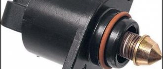
Structurally, the IAC on the VAZ 2107 is an electric motor, which consists of a stator, a magnetic rotor and a spring-loaded rod mechanism with a locking tip. The ECU sensor controls the opening of the damper to a certain area.
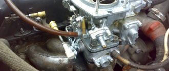
For carburetor engines, a different solenoid valve operation scheme is used. The regulator is installed in the carburetor; it is based on an electromagnet with a locking part. When voltage is applied from the ECU, the valve releases passage in the fuel nozzle.
Removing the speed sensor of a VAZ-2107-20 car
The vehicle speed sensor is installed on the gearbox between the drive and the speedometer cable. Its operating principle is based on the Hall effect. The sensor outputs rectangular voltage pulses to the controller with a frequency proportional to the wheel speed.
We carry out the work on an inspection ditch or overpass.
Turn off the ignition.
1. By pressing the spring clip, disconnect the speed sensor wire block from the engine control system wiring harness block.
2. Unscrew the union nut of the speedometer cable and disconnect the cable from the speed sensor.
3. Using a 22 key, loosen the tightening and unscrew the sensor by hand.
4. We install the speed sensor in the reverse order. In this case, the shank (square section) of the sensor shaft must fit into the hole in the gearbox shaft, and the shank of the speedometer drive cable into the hole in the speed sensor shaft.
https://youtube.com/watch?v=VoOLCDdab50
Sources
- https://remontauto-vaz.ru/page/datchik-skorosti-vaz
- https://carfrance.ru/zamena-datchika-skorosti-vaz-2114/
- https://autoruk.ru/2101-2107-klass/vaz-2107-20/kak-zamenit-datchik-skorosti
Location of the sensor on the VAZ 2107
In injection engines, the sensor is located on the intake manifold in the throttle block.
In carburetor engines, the control solenoid valve is located in the unit block.
Adjusting the float system of the VAZ 2107 carburetor
- Determine the location of the float. If necessary, it is worth aligning the holder bracket (then the float will lower into the chamber evenly).
- Make adjustments with the needle valve closed. To do this, open the chamber cover, move the float to the side, and pull the bracket tongue. It is necessary to achieve the desired value: the distance from the float to the cover gasket should be 6-7 millimeters, and in a submerged state - 1-2 millimeters. If the distance is greater, the needle is faulty.
With the needle valve open, the distance from the needle to the float should be 15 millimeters.
The adjustment should be made with the carburetor disassembled or directly on the engine.
Signs of breakdown
Problems with engine operation during idling are not always associated with a malfunction of the fuel system. For carburetor engines that use a classic ignition circuit, a jumping stroke in 70% of cases is associated with a broken group of contacts and incorrect carburetor settings.
The carburetor magnetic valve operates only when the ignition is on. Therefore, before repairing a part, the quality of the power supply to the central wire of the carburetor and the integrity of the circuit are checked. Causes of unstable engine idle speed:
- The carburetor is clogged with dirt.
- The winding in the IAC has burned out.
- Clogged jets, fuel or air filter.
- Incorrect carburetor setting.
The first signs that the IAC has burned out on an engine with a distributed injection system:
- Unstable operation of the internal combustion engine (stalls if the accelerator is released, troits).
- The revolutions float (decrease or increase).
- The engine power decreases and a difficult start is felt.
If the regulator is burnt out, the engine computer signal system does not display the CHECK error on the instrument panel, so the part is diagnosed based on the symptoms when checking the system.
Why is the engine speed unstable?
When it comes to the carburetor, there are several reasons:
- The carburetor is clogged, the movement of air and gasoline becomes impossible.
- The operation of the solenoid valve is disrupted - the winding is burned out or the nozzle is clogged.
- Fuel or air filters are clogged.
- Incorrect carburetor adjustments on VAZ 2107.
In most cases, the culprit is the solenoid valve. Its appearance is shown in the photo. It is necessary in the power system for the following purpose - it opens the fuel supply when the ignition is turned on and closes it when it is turned off. Consequently, the engine stops immediately after turning off the ignition.
The VAZ 2107 carburetor solenoid valve is a small device consisting of the following elements:
Frame.
Winding (one end connected to a metal body).
A rod that acts as a valve that opens and closes the fuel supply at idle.
Copper jet with holes
Please note that the jets are marked and there are several sizes. The solenoid valve operates only when the ignition is on
If suddenly there is a break in the power circuit, you can temporarily connect the central wire of the device to the positive terminal of the battery. Just try to carry out repairs as soon as possible.
The solenoid valve operates only when the ignition is on. If suddenly there is a break in the power circuit, you can temporarily connect the central wire of the device to the positive terminal of the battery. Just try to carry out repairs as soon as possible.
Diagnostics of IAC electrical wiring
Before replacing or cleaning a part, check the supply circuit with a multimeter. The order of ringing the chain step by step:
- Locate the sensor wires in the electrical cable block.
- Disconnect the block, turn on the ignition.
- Switch the multimeter to voltmeter mode, connect the minus probe to ground (car body).
- Plus, alternately apply “A” and “D” to the output.
If the voltage is similar to the parameters of the on-board electrical network (approx. 12 V), the supply circuit is in order. If the voltage is less than 10 V or there is no voltage at all, check the car's wiring.
Checking the EPHH needle valve.
We also remove the hose from the side outlet (fitting “2”) of the electro-pneumatic valve and connect this hose to the economizer. We start the engine. If the economizer valve is working properly, the engine should run at low speed. If the engine stalls at idle, the valve diaphragm may rupture.
To change the valve, disconnect the wires from the microswitch terminals.
2. Using a screwdriver, unscrew the two screws securing the economizer housing to the carburetor.
3. Remove the bracket with the microswitch...
4. ...as well as the economizer assembly.
5. Remove the gasket from the economizer.
6. Unscrew the two bolts holding the body and economizer cover together...
7. We halve the economizer and check the condition of the diaphragm.
If the diaphragm is defective or the needle and seat are worn, we replace the economizer assembly.
On older models it was possible to change parts individually.
We install the new economizer in the reverse order.
Replacement
Diagnostics, cleaning and replacement of the throttle body is carried out after removing the throttle unit from the car.
The sensor is carefully removed from the dismantled unit and inspected. To check the performance of the dhx, use a tester switched to ohmmeter mode. Step by step diagnostic procedure:
- Set the measuring range on the tester to 0-200 Ohm.
- Attach the probes to the terminals, first on “A” and “B”, then “C” and “D”. The working element will show a value within the range of 50-53 Ohms.
- Take measurements between opposite pairs: “A” and “C”, then “B” and “D”. On a working unit, the instrument readings should tend to infinity.
If the electrical parameters are normal, the rod is measured - the overhang length should not exceed 22 mm.
If the rod is jammed, its size is increased, there are no optimal indicators of the multimeter, the part is changed. It is not advisable to repair the sensor.
Speed sensor replacement process
As practice shows, the original speed sensor of the VAZ-2114 is not particularly reliable and durable, so it has to be changed quite often.
This is due to the wear of internal elements, which are constantly in motion and under the influence of temperature, as well as the breakage of the contact group.
Tool
So, as always, before moving directly to the replacement process itself, it’s worth understanding the tools that will be needed to complete the action: a new sensor and a set of keys (namely 10, 14, 21).
Algorithm
Now that everything is assembled, you can proceed directly to the replacement process itself. In order to avoid getting burns, it is necessary to carry out all work ONLY on a cold engine. Therefore, if the motorist has just arrived, it is worth letting the main power unit cool down. So, let's move on directly to the sequential process of replacing the speed sensor:
- Remove the negative terminal from the battery.
- Find the location of the speed sensor.
The designers placed it near the gearbox oil dipstick. - In order to unscrew the sensor, you will have to remove the absorber.
- Remove the wire connector from the sensor.
- We remove the sensor counterclockwise.
- The process was quite easy and simple.
- Assembly is carried out in reverse order.
Features of tuning carburetor engines
In the VAZ 2107 engine, the carburetor uses an undistributed fuel mixture supply circuit, there is no idle speed sensor as such in the system, the operation of the entire solenoid valve block is checked: jets, spring-loaded mechanism and power quality.
Malfunctions can be eliminated by flushing the carburetor, cleaning the jets and channels. It remains mandatory to adjust the fuel level in the float chamber and check the jets for compliance with the markings, since the parts have different sizes.
And that's how it all started. It started with the fact that in the summer, on those very days when the sun is hot on the belly and you want something cooling, I noticed that the baby began to mope, namely, to jump in speed. I think what's the joke? Since I have already said that I am a techie and I think it is necessary to figure out what’s going on. I followed the simple path through trial and error. I started disconnecting the sensors one by one and found out that the Idle Air Control sensor (hereinafter referred to as IAC) had preserved its brains.
I went to the spare parts store for the boys and the superman for spare parts gave me a sensor, and I mentioned that I have an injection pump and at the same time I’ll change the TPS sensor. I gave unrealistic hazel grouse for this pleasure and happily wandered to the place of the campicnic. I installed everything without problems, but this sensor (which is on the right in the photo) seemed cloudy to me.
But in the end everything stood up and worked as it should. After driving a couple of kilometers, I returned from my beloved and my gas pedal began to live its own life, namely, it did not return and did not want to be pressed. This caused the revs to jump again. As always, I’m slightly perplexed and think wow, this is a classic VAZ, everything here breaks and fixes itself, etc. and so on. I park in the hacienda, open the hood and look at the cable - everything is ok. I look closely, and the spring fastener on the throttle has fallen off
What a joke I thought. I took it apart and saw that oil appeared in the throttle, which should not have been there.
I cleaned the entire system, really blew smoke all over the yard like at a Rammstein concert, oh well, I changed the throttle to a new one (after suffering with its cooling pipes), but the problem with the speed remained. I thought that not caring about it would do. Then I drove around and learned to adjust everything with the clutch, which of course is not very correct. And so, before the New Year, I stopped by Auto 49 to pick up wipers and even asked about the sensor. To which Superman says to me: “The IAC sensors are not of high quality, they say, this batch arrived and we don’t know what to do since the summer.” I think it’s absolutely beautiful, you know, I’m driving around thinking what a fantasy it is, and it turns out they have a leftist lying down. Super easy! I went to my trusted spare parts at Petrashka. They gave me a sensor, and I say it already looks like a normal sensor (pictured on the right)
I arrive joyfully into a cozy courtyard, open the hood, take the screw, and try to unscrew the figurines. As a result, I had to remove the throttle and unscrew everything normally, I put the kit back together, turn the IGNITION key, all the strength and power of my engine comes together and it starts. Everything works like clockwork, pure bliss.
So people, having the hands, strength, time and endurance, can repair the cars themselves. And don’t forget that even in branded stores there are low-quality parts, always check if possible. What is my lesson now? All the best. And thank you for taking a couple of minutes to read this post.
Today I will tell you how to check the idle air sensor; by the way, the correct name is not the sensor, but the idle air regulator. Due to the fact that this device regulates engine idle speed, and does not read any indicators. Let's look at the breakdown of this sensor and what can be done about it using the example of a VAZ 2110 car, but the IAC is not much different in other cars. I forgot to say IAC is the Idle Air Controller in abbreviation. I myself often call it a sensor, so if later in the article you come across the words regulator or sensor, then don’t be too indignant.
Carburetor adjustment
Adjusting the carburetor involves several steps:
- Adjust the position of the float as described above.
- Check and set the “quality” and “quantity” screws to the initial state. Screw them all the way and unscrew them 2-3 turns for the “quality” screw and 3-4 for the “quantity” screw.
- Connect a tachometer or auto tester to the “K” terminal of the ignition coil, and the second probe to the housing.
- Start and warm up the engine to a temperature of 90°C
- Use the “quality” screw to set the maximum idle speed. The gasoline supply increases when the screw is rotated counterclockwise.
- Use the “quantity” screw to set the speed higher, approximately 80-90 rpm.
- Using the quality screw, we determine whether these speeds are maximum; if not, then we repeat the procedure.
- If the position of the quantity screw does not affect engine speed, tighten the quality screw so that the speed drops by 800-900 rpm.
This carburetor adjustment may not be entirely accurate, but does not require special equipment.
Symptoms of a broken IAC sensor
I will give several examples of how a car can behave if the idle air control valve breaks down. There are also a few examples of how you can independently discover that your IAC is not working.
- The first situation
and the most obvious way to detect the appearance of the Check Engine indicator on the dashboard. Using your phone or laptop, you can connect to your vehicle and find out why the Check Engine message is appearing. - The second situation is
“Floating idle speed”, the engine spontaneously increases speed, then decreases. Sometimes the spread of such fluctuations can reach several thousand. - Third situation
. The engine starts and immediately stalls, but continues to run if you press the gas pedal. - Fourth situation
. The engine needs much more time to warm up and reach normal operating mode, and until this point, unstable operation appears.
Checking status
If you have a tester for checking, the procedure is simplified. But you can diagnose performance without the help of special analyzers. Here you cannot do without the help of a friend, colleague, neighbor or just an acquaintance. You need to connect the connector to the removed sensor. Gently place your finger on the tapered needle and its tip. At the same time, you need to remember that you cannot put pressure on the needle. After this, please start the car (turn on the ignition). The finger should feel slight vibrations (shocks). This indicates the operating condition of the regulator.
Next, we inspect the IAC itself to identify its contamination. It is necessary to clean it, as this will increase its service life and affect the engine speed and its operation. It is easy to clean. We take a special cleaner designed for the carburetor. It is inexpensive, sold in any auto store, as well as in many hypermarkets in the car department. Dip a cotton swab into the liquid and carefully rinse all contacts.
We also fill the rod, spring and cone needle with cleaner and use an old toothbrush to remove all dirt. To improve performance, we also clean the throttle valve. Before returning the IAC to its place, it is better to also clean the valve and its seat, as well as the entire surface area on which the O-ring is attached. We coat the sealing ring itself with engine oil and put everything back in place in reverse order.
Where is the idle speed sensor located?
Different cars have different equipment and different locations of sensors and power units in the engine compartment. However, on any car you need to start looking for this sensor from the air intake unit. Since it is the IAC that regulates the flow of air for mixing with gasoline.
Using the VAZ 2110 as an example, let’s pay attention to the far part of the engine from the passenger compartment.
Irregularities in the operation of the VAZ 2107 engine at idle speed are a fairly common phenomenon. And if we are talking about a power unit with distributed injection, then very often the cause of such problems is a malfunction of the idle air controller (IAC). We will talk about it in this article.
General concepts and operating principle
A sensor is a specialized device belonging to the group of measuring instruments, used for processing and converting data, as well as displaying it on a mechanical or electronic display in the form of an understandable digital value.
As it becomes clear, IAC is not a completely rational name for the device in question; it would be more correct to say - idle air control (IAC).
So, the idle air regulator is one of the most important components of an internal combustion engine and plays a significant role in the smooth and uninterrupted operation of the car as a whole.
The idle speed control is an actuator, malfunctions of which are very difficult to identify with your own hands.
This is explained by the fact that the systems of VAZ cars do not provide for its self-diagnosis - in case of various malfunctions and malfunctions in the regulator, the “check engine” indicator light does not light up.
Idle speed regulator (sensor) VAZ 2107
In everyday life, the IAC is called a sensor, although it is not one. The fact is that sensors belong to measuring equipment, and regulators belong to executive equipment. In other words, it does not collect information, but executes commands.
Purpose
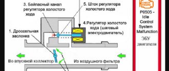
The IAC is a component of the fuel supply system of an engine with distributed injection, regulating the volume of air entering the intake manifold (receiver) when the throttle valve is closed. In fact, this is an ordinary valve that slightly opens the spare (bypass) air channel by a given amount.
IAC device
The idle speed control is an electric motor of a stepper design, consisting of a stator with two windings, a magnetic rotor and a rod with a spring-loaded valve (shut-off tip). When voltage is applied to the first winding, the rotor rotates to a certain angle. When it is fed to another winding, it repeats its movement. Due to the fact that the rod has a thread on its surface, when the rotor rotates, it moves back and forth. During one full revolution of the rotor, the rod takes several “steps”, moving the tip.
Operating principle
The operation of the device is controlled by an electronic unit (controller). When the ignition is turned off, the IAC rod is pushed forward as much as possible, which is why the passage hole of the bypass channel is completely blocked, and air does not enter the receiver at all.
When the power unit starts, the electronic controller, based on data received from temperature and crankshaft speed sensors, supplies a certain voltage to the regulator, which, in turn, slightly opens the flow area of the bypass channel. As the power unit heats up and its speed decreases, the electronic unit through the IAC reduces the flow of air into the manifold, stabilizing the operation of the power unit at idle.
When we press the accelerator pedal, air enters the receiver through the main channel of the throttle assembly. The bypass channel is blocked. To correctly determine the number of “steps” of the device’s electric motor, the electronic unit additionally uses information coming from the throttle position, air flow, crankshaft position and speed sensors.
When additional load occurs on the engine (turning on the radiator fans, heater, air conditioner, heated rear window), the controller, through the regulator, opens a spare air channel to maintain the power of the power unit, preventing dips and jerks.
Where is the idle air control on a VAZ 2107?
The IAC is located in the throttle body. The assembly itself is attached to the rear of the engine intake manifold. You can determine the location of the regulator by the wiring harness that fits its connector.
Idle speed control in carburetor engines
In carburetor power units of the VAZ 2107, idle speed is ensured using an economizer, the actuator of which is an electromagnetic valve. The valve is installed in the carburetor body and is controlled by a special electronic unit. The latter receives data on the number of engine revolutions from the ignition coil, as well as on the position of the throttle valve of the primary chamber of the carburetor from the contacts of the fuel quantity screw. Having processed them, the unit supplies voltage to the valve, or turns it off. The design of the solenoid valve is based on an electromagnet with a shut-off needle, which opens (closes) the hole in the idle fuel jet.
Adjusting the idle speed of a car engine with carburetors 2105, 2107 Ozone
Adjusting the idle speed of carburetors 2105, 2107 Ozone and their modifications is one of the most frequently performed operations in carburetor maintenance. As a result, it is necessary to achieve stable engine operation at a crankshaft speed of 850-900 rpm, as well as to normalize the content of CO and CH in the exhaust gases.
If the idle speed is adjusted incorrectly, the engine may start and immediately stall, it may stall, during acceleration there may be a “failure”, and during operation there will be increased fuel consumption.
Tools required for adjusting XX speed
— tachometer (you can use the one built into the instrument panel) — slotted screwdriver (3 mm)
In the absence of a tachometer, it is possible to adjust the idle speed by ear. But for this you must have at least some experience in car repair, since it is necessary to distinguish when the speed is normal and when it is increased or decreased.
Preparatory work
Before making adjustments, you must first make sure that the ignition timing is set correctly. The distributor cover, breaker contacts, armored wire and spark plugs are in good condition.
If the carburetor is after disassembly and reassembly or you simply need to set the initial value of the adjustment screws, then first tighten them completely, and then turn out the “quality” screw by 1-2 turns, and the “quantity” screw by 2-3. More details: “How many revolutions should I turn out and tighten the “quality” and “quantity” screws of the Ozone carburetor.”
— Warm up the engine to operating temperature (85-95 0). — With the engine stopped, connect the tachometer and start it again.
The procedure for connecting an autotester (tachometer)
— Rotate the “quality” screw and set the maximum idle speed
We rotate the screw both counterclockwise and clockwise, trying to catch the optimal position of the “quality” screw at which the XX speed is maximum.
Rotate the “quality” screw of the carburetor fuel mixture 2105, 2107 Ozone counterclockwise and clockwise
— Use the “quantity” screw to set an even higher rotation speed
For example, 80 rpm more. We also rotate the screw both clockwise and counterclockwise, trying to increase the idle speed.
We rotate the “amount” screw of the fuel mixture counterclockwise, increasing the total amount of the fuel mixture entering the engine cylinders, clockwise we increase the amount of air and optimize the composition of the mixture (it burns better)
Simply rotating it back and forth.
We check by rotating the “quality” screw in different directions whether the set idle speed is maximum
If not, then we carry out the above adjustments again.
Notes and additions
If, after such an adjustment, the content of CO and CH emissions does not correspond to the norm or the idle speed cannot be adjusted, then it is necessary to check:
— whether the fuel and air jets of the main dosing system are dirty; — whether the main fuel jets of the first and second chambers are reversed; — whether the fuel level in the float chamber is increased; — Is the needle valve working? - Is the fuel jet of the idle system clogged; — whether the holder of the fuel jet of the idle system or the solenoid valve has turned away; — whether the tubes have come off the electro-pneumatic valve; — whether the rubber o-ring on the fuel mixture “quality” screw is damaged.
— In some cases, it makes sense to modify the carburetor idle system. See “Modification of the idle system of Solex and Ozone carburetors.”
Twokarburators VK - More information on the topic in our VKontakte group, on Facebook Twokarburators FS and on Odnoklassniki - Twokarburators OK
Signs of IAC malfunction
Signs that the idle air control valve is faulty may include:
- unstable idling (the engine troits, stalls when the accelerator pedal is released);
- decreasing or increasing the number of engine revolutions at idle (floating speed);
- reduction in the power characteristics of the power unit, especially with additional load (turning on the heater fans, radiator fans, heated rear window, high beam, etc.);
- complicated engine starting (the engine starts only when you press the gas pedal).
But here it should be borne in mind that similar symptoms may also be inherent in malfunctions of other sensors, for example, throttle position sensors, mass air flow or crankshaft position sensors. In addition, if the IAC malfunctions, the “CHECK ENGINE” indicator lamp on the dashboard does not light up, and it will not be possible to read the engine error code. There is only one way out - a thorough check of the device.
Principle of operation
The idle speed sensor is a closed-type system and has feedback, that is, all components represent a conditional closed circle:
Accordingly, according to the scheme:
- Actuator - idle speed sensor;
- Sensor - any device that reads engine rotation speed (crankshaft or camshaft sensors);
- The object of regulation is the engine speed.
When the engine is idling, the throttle valve is in the closed position, and the required amount of air enters through the bypass (“bypass” - bypass), the width of the channel of which is determined by the XX sensor. The amount of air passing behind the damper is read by its mass flow sensor, and this directly affects the amount of fuel supplied through the injectors.
- The comparison circuit is an electronic engine control unit. It compares the engine speed set by the mechanisms and the actual engine speed, and also issues a command to open/close the bypass air channel, bypassing the throttle valve, which ensures uniform engine operation.
That is, the XX sensor, by opening the air channel, increases engine speed, thereby ensuring its warming up at higher speeds, which significantly reduces the warm-up time. After which, receiving a command from the electronic control unit, depending on the engine temperature, it gradually closes the bypass channel until the engine reaches a stable idle speed.
Checking the idle air control circuit
Before moving on to diagnosing the regulator itself, it is necessary to check its circuit, because the reason that it stopped working could be a simple break in the wires or a malfunction of the electronic control unit. To diagnose the circuit, you only need a multimeter with the ability to measure voltage. The procedure is as follows:
- Raise the hood and find the sensor wiring harness on the throttle assembly.
- Disconnect the wiring harness block.
The voltage between ground and each of the terminals must correspond to the voltage of the on-board network, i.e. approximately 12 V. If it is less than this indicator, or is absent at all, you need to diagnose the wiring and electronic control unit.
Selecting a speed sensor (items)
After considering the replacement process, it is worth deciding on the choice of the sensor itself.
2111-3843010 - original catalog number of the VAZ-2114 speed sensor.
Of course, many motorists have noticed that it has a plastic rod that is quite easy to break, and therefore it is not reliable enough.
Analogue
The way out of the situation of a low-quality factory sensor can be an analogue, which can be easily installed instead of the original. The Fenox company offers a part with article number SS10102O7 - a fairly high-quality non-original part that has managed to win the hearts of motorists.
Diagnostics, repair and replacement of idle air control
To check and replace the regulator itself, you will need to dismantle the throttle assembly and disconnect the device from it. The following tools and resources will be needed:
- screwdriver with Phillips bit;
- slotted screwdriver;
- round nose pliers;
- socket wrench or socket 13;
- multimeter with the ability to measure resistance;
- calipers (you can use a ruler);
- clean dry cloth;
- coolant for topping up (maximum 500 ml).
Dismantling the throttle assembly and removing the IAC
To remove the throttle assembly, you must:
- Raise the hood and disconnect the negative cable from the battery.
- Using a slotted screwdriver, hook the end of the throttle cable and remove it from the gas pedal pin.
- On the throttle block, use round pliers to disconnect the clamp on the throttle valve drive sector.
Video: removing and cleaning the throttle assembly on a VAZ 2107
Removal and installation of TPS
The first step is to disconnect the minus terminal from the battery, and then disconnect the chip with the power wires from the sensor, as shown in the photo below:
Now, using a Phillips screwdriver, unscrew the two screws securing the sensor to the throttle assembly.
After both screws are unscrewed, carefully move it to the side.
The seat has a special foam pad that needs to be kept intact. The new sensor is installed in the reverse order, so that the holes in it coincide with the holes in the throttle.
The price of a new TPS for injection VAZ 2104, 2105 and 2107 is about 200-500 rubles. The cost depends on the manufacturer and place of purchase.
How to check the idle air control
To check the IAC, perform the following steps:
- Turn the multimeter into ohmmeter mode with a measurement limit of 0–200 Ohm.
- Connect the probes of the device to terminals A and B of the regulator. Measure the resistance. Repeat the measurements for terminals C and D. For a working regulator, the resistance between the indicated terminals should be 50–53 Ohms.
If the resistance value between the listed terminals does not correspond to the specified values, or the stem overhang is more than 23 mm, the idle air control regulator must be replaced. There is no point in trying to repair the device. In the event of a break or short circuit in the stator windings, and it is these faults that cause changes in the resistance at the terminals, the regulator cannot be restored.
Cleaning the idle air control
If the resistance is normal and the length of the rod is fine, but it does not move after connecting the voltage, you can try to clean the device. The problem may be that the worm mechanism that moves the rod is jammed. For cleaning, you can use a rust-fighting liquid such as WD-40 or its equivalent.
The liquid is applied to the rod itself where it enters the regulator body. But don’t overdo it: you don’t need to pour the product inside the device. After half an hour, grab the rod and gently twist it from side to side. After this, check its functionality by connecting the wires from the battery to terminals D and C, as described above. If the regulator rod begins to move, the device can be used again.
Removal
2. Using a Phillips screwdriver, unscrew the two screws securing the idle air control to the throttle body.
3. Remove the idle speed control. An O-ring is installed at the connection between the regulator and the throttle body. Replace a ring that has lost elasticity or is cracked.
4. Using an ohmmeter, measure the resistance between the terminals of the windings.
The electrical resistance between terminals AB and CD should be within 52-53 Ohms. The resistance between pins AC and BD should be high (tend to infinity). A faulty regulator must be replaced.
Attention! Before installing a new regulator, you must ensure that the valve needle protrudes no more than 23 mm.
5. Using a caliper, measure the protrusion of the needle of the new valve.
6. If the needle protrusion is more than 23 mm, its position must be adjusted. To do this, we apply a voltage of 12 V from the battery to terminal D of the regulator (the connection of the wire to the terminal must be insulated). With the bare end of the wire connected to the negative terminal of the battery, briefly touch terminal C of the regulator. Since the valve moves slowly, we touch it repeatedly, simulating the operation of a switching power supply. After installing the needle in its extreme position, check the protrusion of the needle, which should be 23 mm. Otherwise, replace the valve with a new one.
