Hi all! Friends, today we have a seemingly simple topic - central locking. Everyone has heard about this car component, many use it regularly. But do you know what kind of block this is, what an activator is and what the essence of the central lock is?
Everything here is not as simple as it seems at first glance. From an operational point of view, the device is elementary. You pressed a button, turned the key, and you managed to close all the doors with your own hands, or unlock the trunk compartment, etc. Central locking is not just a remote control or a key that locks and unlocks everything in the car with one magical movement.
If you suddenly find that the car won’t lock, the key to all the doors has stopped working, as they say, you need to know not only the addresses of good service stations. Repairs are not always worth doing yourself. But at a minimum, you need to know where the central lock is located, what it consists of and how it works. I propose to share this information. I hope you find it useful while operating your car.
What is central locking
Central locking (CL) allows you to lock all doors in the car at once. Of course, without the help of this mechanism, the driver could also open and lock his car: not remotely, but manually. The presence of a central lock does not in any way affect the technical properties of the vehicle, so manufacturers classify this mechanism as a system that ensures the comfort of the car owner.
The central locking can be controlled either by the remote control or by turning the key in the driver's door
Door locking using central locking can be done in two ways:
- centrally (when one press of the key fob button closes all doors at once);
- decentralized (such a system allows you to control each door separately).
The decentralized system is the most modern version of the door locking device. In order for it to perform its functions, an electronic control unit (ECU) is additionally installed on each door. In the centralized version, all the doors of the car are controlled by a single unit.
Conclusion
Automobile manufacturers do everything necessary to ensure that operating a car is not only a comfortable experience, but also completely safe. It is for this purpose that all sorts of additional systems and auxiliary mechanisms are being introduced into modern vehicles. In particular, almost any car is equipped with a central locking or centralized door locking system. This option allows you to open all the doors in the car at once and without making any physical effort, since the locking process is carried out automatically, but if necessary, it can also be done manually.
Author: Oleg Mokrov
Features of the central lock
The central locking system in a car has several features that make the interaction between the system and the driver as simple and effective as possible.
- The central locking system can function successfully in combination with any alarm system.
- The trunk is also connected to the central locking system, but its opening can be controlled separately from the doors.
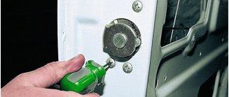
- For the convenience of the driver, the remote control button is located on the key fob and in the vehicle interior. However, you can also close the central locking mechanically by turning the key in the driver's door lock. Simultaneously with turning the key, all other doors of the vehicle will be locked.
In winter, during severe frosts, the elements of the central lock may freeze. The risk of freezing increases if moisture enters the system. The best way to solve the problem is a chemical defroster, which can be purchased at a car dealership. To get inside the car, just defrost the driver's door and start the engine. When the car warms up, the remaining locks will thaw on their own.
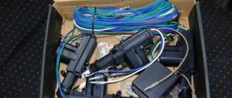
A complete set of elements necessary for installing a central lock
System design
In addition to the control unit, the central locking system also includes input sensors and actuators (actuators).
Input sensors
These include:
- door limit switches (limit switches), transmitting information about the location of car doors to the control unit;
- microswitches that fix the position of the structural elements of the door lock.
Microswitches perform different functions.
- Two of them are designed to fix the cam mechanism of the front doors: one is responsible for the lock signal (closing), the second – unlock (opening).
- Also, two microswitches are responsible for fixing the position of the central locking mechanisms.
- Finally, another switch determines the position of the lever mechanism in the lock drive. This allows you to evaluate the position of the door relative to the body. As soon as the door is opened, the system closes the switch contacts, as a result of which the central locking cannot operate.
The signals sent by each of the sensors enter the control unit, which transmits commands to the actuators that close the doors, trunk lid and fuel tank flap.
Control block
The control unit is the brain of the entire central locking system. It reads information received from input sensors, analyzes it and transmits it to actuators. The ECU also interacts with the alarm system installed on the car and can be controlled remotely using a remote control.
Actuator
The actuator is the final link in the chain, responsible for directly locking the doors. An actuator is a DC electric motor that is combined with the simplest gearbox. The latter converts the rotation of the electric motor into the reciprocating movement of the lock cylinder.
In addition to the electric motor, the actuators used a pneumatic drive. For example, it was used by manufacturers such as Mercedes and Volkswagen. However, recently the pneumatic drive has ceased to be used.
How to connect the alarm to the central locking system yourself?
To independently connect the central locking to the alarm system you need:
- experience working with auto electricians;
- set of tools;
- connection diagram (detailed instructions) taking into account the type of central locking installed on the car.
Preparing tools
The required set of tools for self-installation of an alarm system on a car should consist of:
- a set of Phillips and flat blade screwdrivers;
- wire cutters or scissors for cutting cables;
- set of wrenches;
- pliers or terminal crimping tool;
- knife or wire stripper;
- drill or screwdriver with a set of drills;
- soldering iron;
- network voltage meter;
- insulating tape.
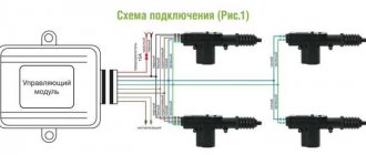
Connection diagrams
The circuits under consideration are intended for car alarms equipped with built-in relays for controlling locks - they have three wires each for locking and unlocking.
The universal connection option looks like this.
Connection diagram of the alarm system to the central locking
Central locking is controlled by constant polarity
The alarm wires connected to the central locking can be power or signal. For power outputs use the following circuit:
The white cable connected to the alarm connector provides a signal for unlocking (UNLOCK), and the green cable provides a signal for locking (LOCK). The relay indicated in the diagram above is responsible for locking. Normally open contacts must be connected to the “minus”; common contacts must be connected to the signal wires of the central locking system.
During installation, please note that the wiring from the connectors of the electronic central locking unit is not cut off - both alarm cables (white and green) are simply connected to it. The security system wires do not have to be connected to the relay connectors; you can connect them to low-current signal terminals.
If the central locking system uses not negative, but combined polarity, then diodes should be installed when connecting (the arrow on them should be directed towards the alarm connector).
To connect to the central locking system with constant positive polarity, the same circuit is used, but with minor differences.
Normally open contacts in this type of central lock are connected to the positive pole, but not to ground. In the diagram, the upper relay gives the command to lock, the lower relay gives the command to unlock. In this option, instead of relay contacts, you can also consider using signal pins, but when installing diodes, the arrow should be directed in the opposite direction - to the central locking connectors.
Central locking controlled by variable polarity
When controlling central locking with variable polarity, the alarm is connected directly to the power wires.
Use a probe to determine the required cables:
- One contact is placed to the positive pole, and the other is looking for a wire, upon contact with which the light bulb of the device lights up. When a command to open or close is sent to the central lock, the probe lamp goes out.
- Then the first probe of the probe is moved from “plus” to “minus” and again sends a signal to the central locking. The device lamp should light up when opening or closing.
When two power wires that control the door lock actuators are found, you need to cut them to connect the alarm.
If the “signaling” has low-current positive/negative outputs, two additional relays are used when connecting
After this, you need to make a connection according to the following diagram:
- NO contacts are connected to the positive wire;
- NC contacts – to cables going to the electronic unit or to the central locking control button;
- O-contacts are connected to control wires going to the door lock drives;
- The alarm output cables are connected to the relay coils on either side.
The second side of the relay is connected depending on the polarity of the car alarm output:
- positive output – to “minus”;
- negative – to “plus”.
Central locking with pneumatics
In pneumatic (vacuum) versions of central locking control, instead of two wires, signals are transmitted one at a time. You can find the control cable in the luggage compartment near the compressor or under the rear seat. When the locks are unlocked, it will have a positive charge, and when locked, it will have a negative charge.
Alarm connection diagram:
The required cable is determined by a probe - one probe of the device is set to “minus”, the other one checks the wiring, closing and opening the central lock. When unlocked, a positive charge is recorded on the control wire, and the device lamp lights up. Then the probe probe is moved to the “plus”, and the other is held on the same wire and when locked, a “minus” should appear.
The found cable is carefully cut and connected to the alarm contacts. To avoid confusion and damage to the electronics, you can apply first a positive, then a negative charge through the probe to the end going to the compressor. If everything is correct, the door locks will open and then close.
If the alarm system being installed has built-in power relays, then the connection is made as follows:
- at the unlocking relay, the NR contact is connected to the “plus”;
- NC contact - into a break in the wire directed to the central locking control button;
- O-contact – to the NC-contact of the locking relay;
- at the locking relay, the NR contact is connected to the “minus”;
- O-contact - into the break in the wire directed to the compressor.
How the device works
The car's central locking can be activated both when the ignition is running and when the ignition is turned off.
As soon as the car owner locks the car doors by turning the key, a microswitch in the lock is activated, providing locking. It transmits the signal to the door control unit, and then further to the central unit. This element of the system analyzes the received information and redirects it to the actuators of the doors, trunk and fuel flap. Subsequent unlocking follows the same pattern.
If a motorist locks the car using the remote control, the signal from it is sent to an antenna connected to the central control unit, and from there to the actuators that lock the doors. At the same time, the alarm is activated. On some vehicle models, the windows on each door may automatically roll up when the doors are locked.
If the car is involved in an accident, all doors are automatically unlocked. A signal about this is transmitted from the passive safety system to the central locking control unit. After this, the actuators open the doors.
Device contents
The remote control central locking kit consists of the following elements:
- control unit;
- actuators;
- input sensors.
Each of these components performs important functions. When purchasing a central lock, you need to pay attention to its performance. Each component should be reviewed in more detail.
"Children's castle" in the car
Children can behave unpredictably. If the driver carries a child in the back seat, then it is difficult to control the behavior of the small passenger. Curious kids may accidentally pull the car door handle and open it. The consequences of a small prank are unpleasant. To eliminate this possibility, a “child lock” was additionally installed on the rear doors of the cars. This small but very important device prevents the door from being opened from the inside.
An additional lock that blocks the opening of the rear doors from the passenger compartment is installed on both sides of the body and is activated manually.
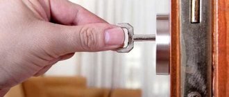
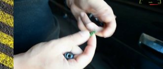
The method of activation of the mechanism depends on the make and model of the car. In some cases, the locking is activated using a lever, in others - by turning the spline. But in any case, the device is located next to the main door lock. For more information on using the child lock, please refer to your vehicle's owner's manual.
“Child lock” allows you to block the opening of doors from the inside and protect small passengers from falling out of the car
TYPE F. Single Wire Positive Control
Control is achieved by changing the level of positive potential on a single-wire line. This type of control is used on Ford Probe and Chrysler vehicles (Fig. 16, 17). This single wire provides both locking and unlocking. To ensure proper operation, both wires from the auxiliary unlock and lock relays must be connected to the same vehicle wire that controls the door locks.
Ford Probe car
The control wire is located under the panel trim at the driver's feet and is green/black. The locking signal is a +12 V positive pulse. The unlocking signal is a +12 V positive pulse connected through a 4.7 kOhm resistor.
Cars Chrysler Cirrus, Dodge Stratus 1995
Models 1993-1995 New Yorker, Concorde, LHS, Eagle Vision have this type of control or 3 wire positive control. This single wire provides both locking and unlocking. To obtain normal operation, both wires from the additional unlocking and locking relays must be connected through appropriate resistors to the same vehicle wire that controls the door locks (see Figure 17). The resistors used provide conversion of +12 V voltage from additional relays into a +3 V lock signal and +6 V unlock signal.
The locking signal is a +12 V positive pulse connected through a 620 Ohm resistor.
The unlocking signal is a +12 V positive pulse connected through a 2.7 kOhm resistor. Control wire color chart (the control wire is located under the driver's side panel trim)
| car model | Wire color | Connector |
| 1995 Chrysler Cirrus | White\light green | Brown 16 pin |
| Dodge Stratus Chrysler New Yorker, Concord, LHS, Eagle Vision, 1993-1995 | Orange\purple | Blue or black 16 pin |
Double locking system
Some cars use a double locking system, where the doors are locked both from the outside and from the inside. This mechanism reduces the risk of vehicle theft: even if a thief breaks the car window, he will not be able to open the door from the inside.
Double locking is activated by pressing the central locking button on the key twice. You will also need to press the remote control twice to open the doors.
The double locking system has an important drawback: if the key or locks malfunction, the driver himself will also not be able to open his car.
The central lock in a car is an important mechanism that allows you to close all the doors of the vehicle at the same time. Thanks to additional functions and devices (such as a child lock or double locking system), the driver can protect himself and his passengers (including small children) as much as possible from the sudden opening of doors during a trip.
Installation Guide
How to install and connect a central locking system with an activator and a remote control with your own hands:
- First of all, the battery is turned off, after which the door trim is removed. Remove all trim, including all screws and fasteners. It is also necessary to unscrew the trim panel under the steering wheel.
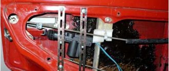
- Next, you need to decide on the location where the device will be mounted. According to many experts, the best option would be to install the central locking system in the lower left corner, since even when the glass is lowered, it will not affect the operation of the central locking system in any way.
- The next stage of installing a system with an activator and a remote control will be the installation of lock activators. All these activators are mounted in the corresponding holes in each door. If there are no holes, you will need to drill them yourself. The activators are fixed with self-tapping screws.
- Next, you need to connect the activator to the lock rod. In this case, the most important point is the alignment of the center of travel of the rods. After these actions, the activators are required to place the fixing elements on the rods of the manual unit. Immediately after connection, you should immediately check whether the circuit is operational.
- Then you should lay out the wiring. The chain that comes from the activators must be securely fixed; for this, use clamps. The clamps should not be installed at the bottom of the door, since moisture often collects there. To do everything correctly, it would be more optimal to purchase a special corrugation or rubber pipe that will protect the wiring from the external environment and bends.
- The next step is to dismantle the control panel (instrument), you need to find the place where the wiring runs, usually it is behind the glove box. You need to connect the activator drives, then insulate and route them. The resulting chain must be laid under the control panel, as well as the glove box.
- Now you need to install the pass-through tube into the rack.
- Then you need to connect a fuse to the connector, and then connect it to the central locking unit. Eventually the center console will need to be assembled.
- Next, the wire is connected from the remote control system to the vehicle. The negative output is connected to the car body, and the positive output is connected directly to the fuse.
- When all connection steps are completed, all that remains is to check the functionality. To do this, connect the battery and check how all the doors close. It would also be a good idea to check the wiring. If everything works fine, reassemble the trim and other interior elements in the reverse order.
Gain access to wiring.
Install a lock on the door.
Connect the central locker to the car circuit.