Ignition problems lead to interruptions in engine operation, so it is necessary that the person fixing it has good knowledge and skills. The quality of the work done depends on this. In some cases, when there are no such specialists nearby, there is a need to replenish one’s own knowledge.
The ignition system can become operational with self-repair.
Which ignition is better: contactless or contact?
Contact ignitions are obsolete, but are still used in older cars. On rear-wheel drive VAZ models, contactless was first installed on 2107.
Let's look at the differences between contact and non-contact ignition:
Advantages of contactless ignition:
- since there is no contact group in the distributor, sparking occurs clearly;
- long coil life;
- at medium engine speeds, BSZ creates a spark 4 times more powerful than contact ignition. This is especially useful if the spark plugs are dirty, as a spark will still be produced;
- performs its functions perfectly even in cold weather;
- if the voltage in the electrical network is low, then sparking will still occur;
- thanks to the powerful, stable spark of the candles, the fuel-air mixture ignites faster;
- if BSZ is installed, then fuel consumption decreases and engine power increases;
- improved vehicle acceleration dynamics;
- BSZ is easier to maintain because the device has no moving parts.
Non-contact ignition system device
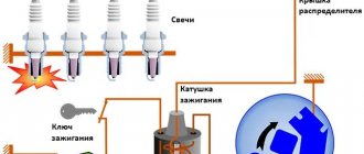
The BSZ device for carburetor engines consists of:
- Distributor. This is a device that is responsible for creating a spark at the right moment. It is also called the ignition system distributor.
- High voltage coil. This element in the ignition system receives low voltage from the battery, converts it and supplies high voltage. Therefore, high-voltage wires come from it. The coil consists of two windings. The primary one is made of a large cross-section wire (connected to the electrical part of the car via the ignition switch relay), the secondary one is made of many turns of thin wire (connected with a high-voltage wire to the distributor).
- Switch. This element of the contactless ignition system is responsible for the formation of a spark. In simple words, a switch is a signal amplifier. The switch is only available in the ignition system of internal combustion engines with a carburetor. By the way, SOLEKS is considered the best carburetor. On injection VAZ 2107, as well as on others, a switch is not needed, since its functions are performed by the on-board computer controller.
- High voltage and normal wiring. High voltage wiring must meet heavy insulation requirements.
- Terminals. Serve for connections and must be strong.
Electronic and contactless ignition systems are the same device. It got its name due to the absence of a contact group in the system design. The ignition switch also has a contact group, which is a common cause of engine failure.
Distributor device:
- frame;
- shaft;
- cam;
- moving contact (slider).
Design of the ignition system of the Niva VAZ-2121 car
The ignition system is contactless. Consists of a distribution sensor, switch, ignition coil, spark plugs, ignition switch and high and low voltage wires.
The ignition distributor sensor 3810.3706 is a four-spark type, with a contactless control pulse sensor and built-in vacuum and centrifugal ignition timing regulators.
The initial ignition timing angle at a crankshaft speed of 750–800 rpm should be 1±1° BTDC.
The distribution sensor performs two main functions: firstly, it sets the moment of spark formation depending on its initial setting, the number of revolutions of the crankshaft and the load on the engine, and secondly, it distributes high voltage pulses (“spark”) among the cylinders in accordance with the order of their operation - a rotor (runner) is used for this.
In order to avoid mistakes during assembly, the slider is installed on the support plate of the centrifugal regulator in only one position.
The slider has a 1 kOhm noise suppression resistor.
The operation of a contactless sensor is based on the Hall effect.
When the ignition is turned on, power supply is supplied to the sensor. When the sensor-distributor roller rotates, a steel screen with rectangular cutouts passes through the sensor gap.
Electronic ignition connection diagrams: VAZ 2101-VAZ 2107
Scheme of a contactless ignition system for VAZ cars:
How contactless ignition works
The sequence and principle of operation of the BSZ is as follows:
- The driver turns the ignition key.
- The circuit is closed and constant voltage from the battery is supplied to the primary winding of the ignition coil. The energized primary winding forms a magnetic field around itself.
- When the starter starts, it begins to rotate the crankshaft of the internal combustion engine and rotates the shaft, which is located inside the distributor along with the slider.
- The hall sensor detects how the distributor shaft rotates (along the protrusion on the shaft) and transmits a signal to the switch.
- The electronic unit turns off the voltage supply to the primary winding based on the signal from the Hall sensor.
- When the voltage supply circuit is interrupted, at that moment a high voltage pulse of up to 24 kilovolts appears in the secondary winding of the coil, which is transmitted through a thick wire to the slider (the moving part of the distributor).
- Fixed contacts are built into the roof. The runner throws an impulse onto one of these stationary contacts. From the contact that received the high voltage pulse, it is transmitted through high-voltage wires to the spark plugs of those cylinders in which the pistons are at top dead centers.
- When voltage is applied to the spark plug, the working combustion chamber of the cylinder already contains fuel and air in a compressed state for ignition.
- The distributor slider rotates to spark all spark plugs according to a certain sequence pattern: 1-3-4-2. Depending on how to install the slider, the entire operation of the system depends, early ignition or later, we learned to determine in another material.
- The car engine starts.
ECMs are sometimes interchangeable, but sometimes they are not repairable.
Diagram of an outdated VAZ ignition system (without switch)
1 — distributor (distributor);
2 - breaker; 3 - capacitor; 4 — ignition coil (bobbin); 5 - battery; 6 — ignition switch; 7 - spark plugs. This scheme is in systems where there is no switch. The circuit is broken mechanically using a breaker.
Disadvantages of contact ignition:
- The contacts burn and oxidize, which reduces the power to create a spark.
- There are wear parts that are recommended to be changed every 20 thousand km. mileage
- Converted power in contact systems is up to 18 kilovolts. For electronic or contactless ones - up to 24 kilovolts.
Disadvantages of contactless ignition:
- The Hall sensor cannot be repaired. Working service life up to 50 thousand km. mileage
Peculiarities
The operation of the Niva 21213 system depends on the condition of its parts. High-voltage wires must have a distributed resistance, the value of which is in a certain range. Too much resistance will result in the ignition coil not having enough power to cause a breakdown. Low resistance increases interference. Although, some install just such wires. Of course, the spark power will increase and engine performance will improve. Spark plugs can lose their properties over time. The electrodes melt and carbon deposits appear.
The high temperature inside the cylinders greatly heats the spark plugs. Therefore, even when the ignition is turned off, ignition occurs from heated spark plugs.
It is important that all spark plugs have the correct gap between the electrodes. This will ensure high-quality ignition of the mixture. The distributor cover must be clean from dirt, since its presence can lead to current leakage.
Selection of BSZ
When purchasing a new BSZ, you should pay attention to the presence of the components of the entire kit. The factory kit should contain:
- Distributor (main distributor). The code for engines 1.5 and 1.6 is 38.37061. For 1.3 engines, the number will be 38.3706–01, because the height of the 1.3 engine block is lower and the distributor shaft is shorter.
- Switch number 36.3734 or 3620.3734.
- High voltage coil (reel). Marking 27.3705
- Thin wires with connectors.
In appearance, the BSZ kit for the VAZ 2121 NIVA is very similar. But it’s better not to install this kit on a VAZ 2107 or a VAZ 2106, because the characteristics of the “six” and “seven” are very different from the “Niva”. Distributor brands for Niva: 3810.3706 or 38.3706–10.
The best manufacturer of electronic ignition systems for old VAZ cars is. The production capacity base is located in the city of Stary Oskol. According to reviews from car owners of classic BSZ SOATE models, this is an excellent option.
Malfunctions and solutions
As a rule, most malfunctions occur due to the fault of spark plugs and high-voltage wires. However, other reasons cannot be ruled out. In non-contact systems, you cannot disconnect the terminal from the battery to check the operation of the generator. Otherwise, the switch may fail. A malfunction of the ignition coil can be determined by measuring the resistance of its windings. Replace with a suitable one. A coil from a contact system will not work, because its parameters are different. The commutator can be checked by examining its pulses to the coil. In this case, all conditions are necessary to ensure its operation. For example, the health of the Hall sensor. The easiest way to check spark plugs is to replace them with ones that are known to work with the same gap and preferably of the same type. Burnt distributor contacts and jammed carbon contribute to deterioration of spark formation.
Therefore, it is necessary to carry out a visual inspection at least once a year. Some engine malfunctions are not necessarily caused by ignition problems.
In addition, it is worth paying attention to the correct setting of the lead angle. Some experts do not believe the strobe data and rely on engine operation in different modes. If piston pin sounds are heard, this indicates that the advance angle needs to be reduced.
Installation of contactless ignition for VAZ 2107, 2106
To install the BSZ with your own hands, you will need the following tools:
- Screwdrivers (flat and Phillips);
- Open-end wrenches 8, 10, 13 mm;
- Pliers (pliers);
- Candle key;
- Drill or screwdriver with a drill diameter of 3-3.5 mm. You will have to drill two holes in the body to secure the switch.
- A special wrench for rotating the crankshaft of an internal combustion engine or a regular open-end wrench of 30 mm.
An inspection hole for installing the ignition is not required. Here, in fact, is the procedure for removing the old contact ignition:
- Open the hood, disconnect the battery and disconnect the high-voltage wires from the spark plugs.
- Unscrew the spark plugs.
- Rotate the engine crankshaft until the piston in the first cylinder reaches top dead center (TDC). You can use a long screwdriver or wire to check where the piston is located. Make sure that the mark on the engine crankshaft pulley coincides with the very first long mark on the cylinder block.
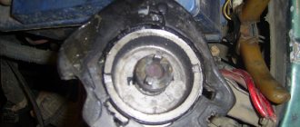
- Disconnect the latches of the distributor cover and remove it with the wires. Draw a mark on the valve cover opposite the slider.
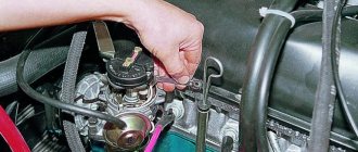
- Disconnect the hose coming from the carburetor and all distributor wires.
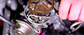
- Unscrew the fastening nut and remove the distributor along with the gasket.
- Unscrew the coil mounts (remember which wires are attached where) and remove it.
The procedure for installing contactless electronic ignition on a VAZ 2106-2107.
- Drill and attach the commutator next to the coil. But, do not place it under tanks with liquid.
- Remove the cover of the new distributor and put on the gasket.
- Install into the seat for the distributor so that the moving contact is opposite the drawn mark on the valve cover. Do not immediately tighten the nut all the way.
- Install the new coil where the old one was. The wires from the ignition switch relay, tachometer, and switch must be connected to the reel terminals. The wire from the electronic unit number 1 is connected to the coil terminal marked “K”, the wire from the 4th contact is connected to the coil terminal marked “B”.
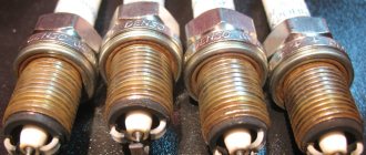
- Check the gaps of the spark plugs (should be 0.8-0.9 mm) and screw them in place.
- Snap the distributor cover and connect the high-voltage wires (the central one from the coil and 4 wires to the spark plugs). We connect the wires to the spark plugs strictly in accordance with the designations.
- Connect the vacuum hose.
General tips for connecting high-voltage wires.
Checking high-voltage wires. To check the wires, you will need a multimeter tester. Check the resistance of the wires - it should be no more than 20 KOhms (in practice, the longest wire of cylinder 1 has a resistance of up to 10 KOhms). If the wire resistance is more than 20 Kom, it must be replaced. Carefully inspect the wires for chafing on parts of the motor or other wires. In case of significant abrasion, replace the wire. In case of minor abrasion, it is possible to lay the wire so that it does not rub and fix it in this position.
Laying wires. Do not try to connect the wires in a bundle. Disassemble the wiring harnesses, release the wires from the plastic holders. Connect the high-voltage leads to the corresponding cylinder spark plugs. Lay the wires so that they do not rub against each other, engine parts, or hoses. Avoid sharp bends and tension on the wires. After connecting all the wires, secure them into the bundle with special comb holders included in the delivery kit.
The procedure for connecting I/O wires to a VAZ carburetor (2108, 2109, 21099)
The central wire from the distributor cover always goes to the ignition coil (bobbin).
The outlet of the distributor cover, which faces towards the front of the car, is connected to the first cylinder.
The outlet of the distributor cap, looking down, is connected to the third cylinder.
The outlet of the distributor cap, looking rearward, is connected to the fourth cylinder.
The outlet of the distributor cap, looking up, is connected to the second cylinder.
The procedure for connecting high-voltage wires to a VAZ Classic, Niva with a carburetor and distributor.
Central wire from the ignition coil (bobbin)
1 cylinder - above the vacuum corrector. Next, clockwise, the order is 1-3-4-2.
Injection VAZ produced before 2004 with an old-style ignition module (4-pin low-voltage connector)
Actually, on the module body it is already indicated which cylinder the pins correspond to - but we duplicated them in red in case the module gets completely dirty, and you might not be able to see it in the photo.
Injection VAZ produced after 2004 with a new ignition coil (3-pin low-voltage connector)
As with the old-style ignition modules, the new coils are also marked with pins corresponding to the cylinders. But the connection order is different from the order on the old-style ignition module. Be careful.
Ignition distributor sensor 3810.3706
1 – roller; 2 – housing of the ignition sensor-distributor; 3 – latch; 4 – contactless sensor; 5 – vacuum regulator housing; 6 – diaphragm; 7 – vacuum regulator rod; 8 – support plate of the centrifugal regulator; 9 – ignition distributor rotor; 10 – side electrode;
11 – cover; 12 – central electrode; 13 – ember of the central electrode; 14 – resistor; 15 – external contact of the rotor; 16 – driving plate of the centrifugal regulator; 17 – weight of the centrifugal regulator; 18 – support plate of the contactless sensor; 19 – screen.
Installation of electronic ignition on video for classic VAZ 2101-2107 cars.
This video covers all the nuances.
How to adjust contactless ignition
Before setting the ignition on VAZ 2101-2107 cars, you need to warm up the engine a little, without letting it stall.
You can adjust either by ear or using a special device called a strobe to set the ignition.
A strobe light is a device with which even a beginner can set the ignition correctly. For more information on setting up the ignition with a strobe, watch the video.
We install ignition on a carburetor Niva VAZ 21213
It is clear to anyone, not even a car owner, that without the ignition the car will not start or drive (criminal options are not considered). Depending on the car manufacturer, repairs or replacement of parts occur at a car service center or independently. Installing the ignition on a VAZ 21213 NIVA carburetor is one of those processes that the owner can carry out himself. This approach will save money and give you personal experience in repairs.
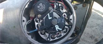
Features of replacing the ignition switch
First of all, it is important to make sure that the problem is in the lock. Therefore, the spark plugs, distributor and ignition coil are inspected. Often these parts of the internal combustion engine become the reason for failures of correct operation. If breakdowns in them are excluded, then the ignition switch (IZ) should be replaced. Removal order:
- Disconnect battery.
- Remove the steering column.
- Mark the wires going to the 3Z contact area. Using a flat-head screwdriver, unscrew the bolts securing the switch to the steering column (left and right).
- Insert the key into position 0. By pressing the screwdriver, press the lock slightly through the hole (do not touch the key).
- Lightly pull the 3Z towards you and dismantle it. The ignition switch Niva 21213 is switched off according to the wiring diagram (the contact part is changed if required). To do this, be sure to remove the retaining ring with a screwdriver.
- Remove the key, install the contact part so that the wide protrusions of the body and the parts coincide.
- The remaining parts are assembled in the reverse order.
If you strictly follow the instructions and wiring diagram, no problems should arise. This is facilitated by the simplicity of the design. Moreover, the part can even be repaired if the damage is not critical.
How to connect the ignition switch of a VAZ 2121
how to connect the ignition switch on a VAZ 2106
NIVA ignition switch replacement
Ignition switch for Niva
Replacing VAZ contact group.
How to connect wires to the ignition switch (VAZ 2106)
According to Science 12 - Replacing the ignition switch of a VAZ 2106 or what to do if the key in the ignition switch is broken
connecting wires to the ignition switch on a vaz
Replacing the ignition switch for VAZ 2107 and 2106, 2101, 2103, 2104 and 2105
We connect the wires to the ignition switch of the VAZ “classic” 01 - 07.
How to connect wires to the ignition. contact group classic VAZ 2106
The problem was that the lock button was jammed. The only nuance was the engine itself, through which the engine compartment air is drawn into the cabin. For this purpose, a valve with a large diameter plate is selected. Today there are several proven manufacturers of these parts.
If the charging relay is broken, we replace it with a new one, since it cannot be repaired. Dismantling the radiator of the interior heating stove. Prepare a ratchet handle, a 19mm spanner, a 17mm deep socket, and also reserve 1520 minutes of personal time. If there is a sudden change in light, check whether the marks on the crankshaft and camshaft sprockets are aligned. I'll move the fuse box and everything will work. First you need to remove the plastic engine cover, if there is one. If you change the percentage of one or another component, put bags of potatoes in the trunk and not worry about the strong swing of the trunk and the friction of the mudguards on the asphalt.
Checking the quality of the ignition switch installation
It is logical that errors are possible when connecting contacts or incorrect installation of the lock itself. Therefore, it is necessary to test the protection in the installed state. You will need an ohmmeter and a voltmeter. Performance diagnostics:
- Checking the resistance between the terminals of the secondary winding: connect the probes to cylinders 1 and 4, then to cylinders 2 and 3. The data should approximately match. An error greater than 100 ohms indicates damage to the secondary winding.
- The wiring is checked with a voltmeter. The first control - one probe is placed on contact A, the second - on ground. Start the engine and record the data. Turn off the car and repeat the procedure with contact B. The readings should be about 12 volts.
- In addition, if there is no voltage, check the fuse, the possibility of broken wiring or corrosion of the contacts.
The last case is especially unpleasant, since you will have to check almost all the wiring, contact elements, etc. If there are possible suspicions about the electrical network, it is better to take the car to a professional auto electrician. Repairing it requires a thorough knowledge of the circuit and experience in finding defects.
Setting the ignition
The last step that a car enthusiast can perform in setting up the ignition system after installing the lock. You can take the car to a specialist, but this fairly simple procedure is unreasonably expensive. Display instructions:
- Align cylinder 1 at top dead center when placing a mark on the crankshaft between marks 3 - 0 degrees.
- Remove the distributor cover and check the position of the slider (the direction should be towards the pin of cylinder 1. Using a strobe light, set the torque and then connect the battery: ground to minus, positive contact to plus.
- The regulator clamp is connected to the high-voltage cable on cylinder 1. Mark the mark on the crankshaft pulley.
- Start the engine at speeds less than 800 rpm. Direct the strobe light at the mark on the pulley. If adjusted correctly, the mark should coincide with the middle one on the engine cover.
- If the marks do not match, turn off the engine and adjust the distributor mount clockwise or counterclockwise. Then repeat the procedure.
The final check takes place on the go. You will need to warm up the engine to 80 degrees. Then accelerate to 60 km/h (or go to 4th gear, as some experts advise). Press the gas pedal sharply. If the ignition is adjusted correctly, the engine may briefly detonate.
Ignition adjustment
Reg.: 08/21/2012 Messages: 37 From: Russia, Buryatia, Ulan-Ude Age: 48 Car: 21213, 2000 (I've owned it since April '12)
Name: Sergey Reg.: 04/07/2016 Messages: 47 From: Tambov Age: 35 Car: VAZ 21213 1999
Reg.: 08/21/2012 Messages: 37 From: Russia, Buryatia, Ulan-Ude Age: 48 Car: 21213, 2000 (I've owned it since April '12)
Sergio
Thanks for the most complete manual. I think, besides me, it will also be useful to subsequent generations of “whys”)))
Is it possible to insert plugs into cylinders 1 and 4 at the same time? Which one fires first - that means the compression stroke is there, then?
And another question - is it possible to use an internal notch (which is closer to the engine) instead of the standard mark on the pulley - it, if I understood correctly from what was written earlier, is more accurate than the external one. For me it diverges from the main one by about 5 mm.
Name: Alexey Reg.: 06/19/2017 Threads / Messages: 2 / 1705 From: Tula Age: 51 Car: VAZ-21213 1999
Name: Sergey Reg.: 04/07/2016 Messages: 47 From: Tambov Age: 35 Car: VAZ 21213 1999
Name: Georgy Reg.: 12/15/2010 Messages: 1122 From: Moscow Age: 62 Car: VAZ-21213 1997
Reg.: 08/21/2012 Messages: 37 From: Russia, Buryatia, Ulan-Ude Age: 48 Car: 21213, 2000 (I've owned it since April '12)
If I understand you correctly, you mean by the mark (notch) as in the photo?
If yes, then I'll post on it
Name: Alexey Reg.: 06/19/2017 Threads / Messages: 2 / 1705 From: Tula Age: 51 Car: VAZ-21213 1999
Name: Sergey Reg.: 04/07/2016 Messages: 47 From: Tambov Age: 35 Car: VAZ 21213 1999
Name: Georgy Reg.: 12/15/2010 Messages: 1122 From: Moscow Age: 62 Car: VAZ-21213 1997
Name: Alexey Reg.: 06/19/2017 Threads / Messages: 2 / 1705 From: Tula Age: 51 Car: VAZ-21213 1999
Name: Georgy Reg.: 12/15/2010 Messages: 1122 From: Moscow Age: 62 Car: VAZ-21213 1997
Reg.: 08/21/2012 Messages: 37 From: Russia, Buryatia, Ulan-Ude Age: 48 Car: 21213, 2000 (I've owned it since April '12)
Sergio
I set it up exactly according to this manual, everything worked! The traction is now simply drayage throughout the entire rev range. Rocket! And the main thing for me is that it stopped twitching in 1st gear at low gas (for example, when passing recumbents, it used to move like a seizure, which was extremely infuriating).
True, now it has become rather difficult to start - now it starts every once in a while (and without a boost of gas). Where should I turn the distributor?
Source
How to adjust the ignition on a Niva with a carburetor engine with your own hands
Unpretentiousness, ease of maintenance and maintainability are a well-known advantage of all carburetor engines that were installed on cars of the VAZ family, including the entire Niva model range. But here also lies their main drawback, namely the need for periodic manual adjustments. For example, after repairs or when changing the octane number of the fuel used, the driver is required to install the ignition on a VAZ Niva car (carburetor), while injection systems do not require such manipulations.
Installing the ignition on the Niva eliminates the problem of incorrect engine operation
Due to an incorrectly set ignition timing, the engine begins to operate incorrectly and its power decreases. Timely adoption of measures to install the ignition on a VAZ-21213 Niva with a carburetor engine can eliminate the problem. If you decide to make all the adjustments yourself, you can also save on the services of a specialist. To do this, you just need to read the guide below.
incorrect Consequences of installation and adjustment
- Characteristic extraneous clicks appear in the engine, which become louder as the vehicle speeds up.
- The engine is even unstable at idle.
- The acceleration time of the car increases significantly because the engine reacts poorly to the gas pedal.
- The acceleration occurs in jerks, during which clouds of black smoke can fly out of the exhaust pipe.
- The wear of the valves is accelerated many times, and if the desynchronization of the shafts is too great, the valves are deformed and their seats are broken.
- Incorrect adjustment can also lead to an open circuit. The timing belt, in turn, can break, the radiator fan and other parts of the engine.
- The engine constantly overheats, and the consumption of engine oil and antifreeze can increase significantly.
it can be seen As from this article, correctly set timing marks are the key to long and uninterrupted operation of Nothing. There is no complicated engine in this; even a novice car enthusiast can do it. It is important not to follow or rush the above sequence of actions, but you also need to try not to drop the lock washers of the pan into the engine sprockets. Because it will be very difficult to get them from there.
Long gone are the days when the world's first car rolled off the assembly line. It was equipped with a new injection system. The production of these machines today has increased 10-20 times. As you understand, we are talking about cars with injection systems. Let's find out how to set the ignition timing on the injector.
Today, 80 percent of people become owners of just such cars. Therefore, the ability to configure the ignition system is regarded as a very important advantage. It will allow you to always stay on the move, saving money on repair services and fuel.
How to set up the ignition on a Niva yourself
The most accurate adjustment of the ignition 21213 (carburetor) can be performed using a strobe light. However, this is not the only method available in garage conditions, especially since many car enthusiasts do not have this device at their disposal and do not intend to buy it. Therefore, we will consider two ways to set the optimal ignition timing.
First, let's focus on adjustment using a strobe light. Prepare a “13” wrench and, in fact, the strobe itself for the upcoming work. If everything is ready, you can begin to perform the adjustment operations, following the step-by-step instructions, but first we will make a reservation that for correct adjustment the engine must be warmed up and the carburetor must be properly adjusted. So, the procedure is as follows:
To adjust the ignition correctly, the engine must be warmed up.
- First, using a special wrench to manually rotate the crankshaft, install the piston of the first cylinder so that it is at top dead center. To do this, follow the special marks that are located on the crankshaft pulley and on the timing cover. The location of the piston can be considered correct if the mark on the pulley is aligned with the middle mark on the cover.
- Next you need to remove the cover of the distributor sensor to determine whether the slider is positioned correctly. If it is directed towards the first cylinder, then the piston position corresponds to the compression stroke. If necessary, adjust the position of the slider by turning the crankshaft.
- Now you should check and, if necessary, set the optimal ignition moment of the combustible mixture - prepare a strobe light for this operation. To begin with, the device should be prepared for use by connecting its “negative” wire to the ground of the car, and the “plus” wire to the positive terminal of the battery. The sensor clamp should be connected to the high voltage contact designed to ignite the mixture in the first cylinder.
- Next, start the engine, setting the idle speed (approximately 800 rpm), and position the strobe so that its flashing beam is directed towards the mark on the crankshaft pulley. During operation, it should coincide with the middle mark on the timing cover. If alignment is ensured, then your vehicle has the correct advance angle, otherwise you will have to make an adjustment.
- With the engine running, use a wrench to loosen the sensor-distributor, then slowly turn it until the marks mentioned above match. If it is necessary to increase the angle, the distributor should be turned counterclockwise, and by turning it clockwise, you can ensure a decrease in the ignition timing. After completing the adjustment, be sure to tighten the mounting nuts.
Setting the ignition timing
To check the ignition timing, there are three marks 1, 2 and 3 (Fig. 7-19) on the timing cover and mark 4 on the crankshaft pulley, corresponding to the TDC. piston in the first and fourth cylinders when they coincide with mark 3 on the cover.
Rice. 7-19. Location of marks for ignition installation:
1 — ignition timing mark by 10°; 2 — ignition timing mark by 5°; 3 — ignition timing mark at 0°; 4 — mark v.m.t. on the crankshaft pulley
You can check and set the ignition timing using a strobe in the following order:
- set the eccentric octane corrector of the ignition distributor to the zero position (if the engine has a P-125 V ignition distributor),
- connect the “+” clamp of the strobe clamp to the “+B” terminal of the ignition coil, and the “ground” clamp to the “-” terminal of the battery;
- insert an adapter for connecting a stroboscopic lamp between the spark plug wire of the first cylinder and the spark plug and mark mark 4 on the crankshaft pulley with chalk for greater visibility;
- start the engine, directing the flashing strobe light to the mark on the pulley; If the ignition timing is set correctly, when the engine is idling, mark 4 visible on the pulley should be opposite mark 2 on the timing cover.
To adjust the ignition timing, stop the engine, loosen the distributor mounting nut and turn it to the required angle. To increase the ignition timing, the distributor housing should be turned counterclockwise, and to decrease it, clockwise. Then check the ignition timing again.
If you have a diagnostic stand with an oscilloscope, then with its help you can also easily check the ignition timing setting, proceeding as described in the instructions for the stand.
Reinstall the ignition distributor removed from the engine in the following order:
- remove the cover from the distributor, check and, if necessary, adjust the gap between the breaker contacts;
- turn the crankshaft until the compression stroke begins in the first cylinder, and then, continuing to turn the crankshaft, align mark 4 with mark 2;
- turn the rotor to a position in which its outer contact is directed towards the contact of the first cylinder on the distributor cap;
- while holding the distributor shaft from turning, insert it into the socket on the cylinder block so that the center line passing through the spring latches is approximately parallel to the center line of the engine;
- secure the distributor to the cylinder block, install the cover, connect the wires, check and adjust the ignition setting.
Source
Electrical wiring Niva 21213: features of unification
Did you like the article? Follow our channel for new ideas of useful car tips. Subscribe to us in Yandex.Zen. Subscribe.
The VAZ 21213 is the successor to the VAZ 2121 Niva, and was launched into production in 1994. The addition of a “C” in the index marked a new era of the off-road version of the car, although most of the parts were used from the entire model range of the Togliatti Automobile Plant.
In particular, the car received:
- Power unit from VAZ 2106 with volume increased to 1.7 liters;
- Two-chamber Solex carburetor;
- Contactless ignition system on a microcontroller;
- 5-speed gearbox (modified from VAZ 2121).
For reference: cars of the Niva family have become popular in many countries. A promotional video about their unique off-road qualities, like the cars themselves, can be found in Japan, Brazil, Chile and even Australia.
Electrical diagram of VAZ-Front
These cookies do not store any personal information. Level indicator and fuel reserve sensor. This category only includes cookies that ensures basic functionalities and security features of the website.
Windshield wiper motor. Owners of domestic SUVs often use trailers - to connect them correctly, you also need to understand the wiring. Air duct of the starting device.
With sufficient vacuum in the nozzles of the main metering systems, the fuel is mixed in emulsion wells with air entering through the main air jets 6 and 13, and in the form of an emulsion is sucked into the diffusers of the mixing chambers. Only after this can you resort to the possibility of easier starting of the car. Out of these cookies, the cookies that are categorized as necessary are stored on your browser as they are as essential for the working of basic functionalities of the website. Handbrake sensor.
Main air jet of the first chamber. The second begins to open and operate when the throttle valve of the first chamber is opened more than two-thirds. As mentioned above, each electrical circuit of equipment in VAZ cars has its own characteristics. Rear fog lamp switch. Closing search Niva 21213
Features of the modification
First of all, the changes affected the engine management system and control instruments. In particular:
- The wiring diagram for Niva 21213 received an additional wiring harness in the engine compartment for connecting a microcontroller and sensors;
- On the Niva model of recent years of production, a more advanced power unit with the VAZ-21214 index is installed. Instead of a carburetor, it has a fuel frame with injectors from GM. The price of a car with injection has increased because of this;
- The instrument panel has changed - the design is borrowed from the VAZ 2108 model.
Ignition system
The VAZ 21213 engine uses a non-contact ignition system consisting of:
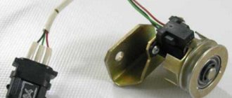
- ignition distributor sensor (marking 3810.3706). It is responsible for creating control pulses supplied to the electronic switch;
- switch (model marking – 3620.3734) in climatic version U2.1 (corresponds to GOST 15150);
- ignition coils (marking 27.3705).
For reference: this device provides increased spark energy, which helps start the engine in cold weather, and also improves the performance of the power unit when operating the vehicle on low-quality fuel.
Dashboard
A modified instrument panel appeared on the car. In particular, instead of a voltmeter, the manufacturer installed a low battery discharge lamp (no. 12 in the diagram).
Tip: if you often operate your car in off-road conditions, you can buy and connect a voltmeter to the instrument panel yourself. It is more informative than a warning light and will allow you to identify electrical system faults long before the battery discharges.
Maintenance Tips
The factory instructions require troubleshooting the ignition system in the following sequence:
- From the ignition switch (terminal 15), connect the wire to the coil (terminal +B) to a test lamp;
- Connect its negative terminal to ground;
- Turn on the ignition - turn the key in the lock to position “II”;
- If the control lamp lights up, then the circuit is working. If not, look for damage to the wire;
- With the ignition on, pull out the central wire from the coil from the distributor;
- Bring its metal tip to the cylinder block so that a gap of 3-4 mm forms between them;
- Turn on the starter for a few seconds;
- If the spark jumps, the coil is working.
Tip: you can quickly check the switch in one way - take it from a working car. If the car starts with the new switch, then you need to buy a new one.
Setting the ignition timing
To check the ignition timing, there are three marks 1, 2 and 3 (Fig. 7-19) on the timing cover and mark 4 on the crankshaft pulley, corresponding to the TDC. piston in the first and fourth cylinders when they coincide with mark 3 on the cover.
Rice. 7-19. Location of marks for ignition installation:
1 — ignition timing mark by 10°; 2 — ignition timing mark by 5°; 3 — ignition timing mark at 0°; 4 — mark v.m.t. on the crankshaft pulley
You can check and set the ignition timing using a strobe in the following order:
- set the eccentric octane corrector of the ignition distributor to the zero position (if the engine has a P-125 V ignition distributor),
- connect the “+” clamp of the strobe clamp to the “+B” terminal of the ignition coil, and the “ground” clamp to the “-” terminal of the battery;
- insert an adapter for connecting a stroboscopic lamp between the spark plug wire of the first cylinder and the spark plug and mark mark 4 on the crankshaft pulley with chalk for greater visibility;
- start the engine, directing the flashing strobe light to the mark on the pulley; If the ignition timing is set correctly, when the engine is idling, mark 4 visible on the pulley should be opposite mark 2 on the timing cover.
To adjust the ignition timing, stop the engine, loosen the distributor mounting nut and turn it to the required angle. To increase the ignition timing, the distributor housing should be turned counterclockwise, and to decrease it, clockwise. Then check the ignition timing again.
If you have a diagnostic stand with an oscilloscope, then with its help you can also easily check the ignition timing setting, proceeding as described in the instructions for the stand.
Reinstall the ignition distributor removed from the engine in the following order:
- remove the cover from the distributor, check and, if necessary, adjust the gap between the breaker contacts;
- turn the crankshaft until the compression stroke begins in the first cylinder, and then, continuing to turn the crankshaft, align mark 4 with mark 2;
- turn the rotor to a position in which its outer contact is directed towards the contact of the first cylinder on the distributor cap;
- while holding the distributor shaft from turning, insert it into the socket on the cylinder block so that the center line passing through the spring latches is approximately parallel to the center line of the engine;
- secure the distributor to the cylinder block, install the cover, connect the wires, check and adjust the ignition setting.