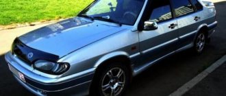
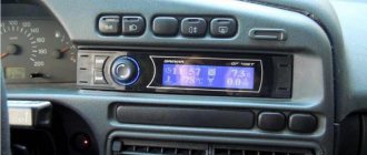
VAZ 2115 and 2114 cars are equipped with modern equipment that allows you to monitor the serviceability of all systems and units of these brands. To repair temporarily faulty lamps of these models, it is not necessary to go to a service station, but you can acquire a simple tool, and knowledge of where the relay is located to monitor the serviceability of the lamps of a VAZ 2114 and 2115 car, and fix the fault yourself.
There is a mounting block in the engine compartment of VAZ 2114 and 2115 cars. Its location can be seen in this photo No. 1
VAZ manufacturers have placed in it various relays, as well as fuses, which are responsible for the operation and monitoring of the serviceability of not only lighting devices, dimensions, car turns, interior lighting, as well as windshield wipers.
In order to open this mounting block, you need to disconnect two clamps from it, as shown in the photo, and remove the special safety cover. This can be done using pliers or other devices, but it is better not to damage these clamps.
Photo 2
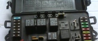
If it is necessary to repair or replace some parts (for example, fuses), then it is better to disconnect the unit itself from the current. To do this, it is disconnected from the battery, that is, the terminals are removed, and then it must be disconnected from the wires connected to it. They are located in a special plug, which is easily separated from the unit itself. Only after this can repairs be made.
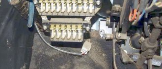
After these manipulations, the VAZ owner will see fuses that have special designations, as well as several relays, and those that are responsible for monitoring the serviceability of the lamps of the VAZ car. If the car has technical documentation, then in the figure these relays for monitoring the health of the lamps will have a special designation. When technical documentation is missing for some reason, then you need to carefully look at the provided photo.
Photo No. 3
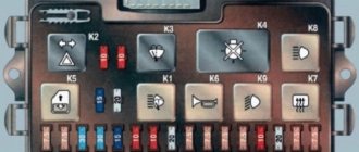
On it, these relays are designated as follows:
- K4, it is responsible for the serviceability of the brake light indicator lamps, as well as the vehicle’s side lights;
- K8 is responsible for the proper operation of the car’s high beam lamps;
- K9 is responsible for the proper operation of turning on the low beam lamps of the car.
So if problems arise, the driver must know which relay is responsible for what. They have special designations, as indicated in photo No. 3.
Also in this mounting block there are fuses that are responsible for the functions of VAZ lamps, and have a resistance designed for a certain current strength, and in the event of overvoltage or a technical malfunction, they give a signal to the relay, which, in turn, outputs it to the dashboard.
The location of this block on the above car models does not change, but in some modifications or years of production, the location of the fuses and the relays themselves, which are responsible for performing certain control functions, may be changed. It is from this block that all the signals go to the dashboard, which inform the driver about a particular malfunction of the car’s light bulbs.
It is important to know that some cars are not equipped with such relays. But if you look closely and disassemble the dashboard, you can find an additional wire leading from the mounting block, where, at the request of the car owner, you can install the relay yourself. After such installation, a light signal will appear on the dashboard, which will indicate a malfunction of the lighting equipment.
Search principle
To find a fault in any vehicle on-board network system, you should use the method of sequential elimination of elements. The point is to consistently check electrical appliances and sections of the circuit, excluding elements from the list of reasons that could cause a breakdown. To do this, you need to clearly understand the design and operating principle of the system. When troubleshooting, you need to move from the components that require the least effort to check, to the most difficult to diagnose elements.
Electrical diagram
We immediately emphasize that the pinout of connectors and color markings of wires may differ not only between different models of the same automaker, but also among one model of different years of manufacture. Before you start searching for the cause of the breakdown, you need to find an electrical diagram specifically for your car model.
We will consider the principle of operation of brake lights and the troubleshooting algorithm using the example of the VAZ 2101-2102 circuit. The photo shows the general diagram of the vehicle's lighting and light signaling. We need to isolate the components involved in the operation of brake lights.
- 6 – mounting fuse block;
- 13 – brake light switch. It is a non-locking button (returns to its original position after removing the force). Located directly next to the brake pedal. When the brake pedal is released, the contacts of the limit switch are open, no current passes through it. Accordingly, when pressed, the contacts close, allowing flow through the lamps;
- 19 – lamps that light up when you press the brake pedal.
We do not have a diagram of the mounting block, but we know in advance that the brake lights only work when the ignition is on. There is a wire from the mounting block to the brake light limit switch, on which there is a constant + after the ignition is turned on. As soon as the limit switch contacts close, + goes to the brake light bulbs, which are connected in parallel. The “ground” of the rear lights is common and consists of a wire screwed to the car body.
In the diagram we presented, the elements are depicted as close as possible to how they look in reality. Don’t be alarmed if you only find a schematic diagram for your car with symbolic images of the elements. Schematic diagram of external lighting for VAZ 2114, 2115:
- 3 – mounting block;
- 8 – lamps for side lights and brake lights;
- 11 – brake light limit switch;
- K4 – relay for monitoring the serviceability of brake light lamps and side lights.
Fuses responsible for monitoring the lamps of a VAZ car
Despite the presence of special relays in the mounting block, the driver must also pay attention to the markings of the fuses that are responsible for controlling the lighting devices. In some cases, precisely because they burn out, the relay begins to signal lamp failure.
F 1 -10 amperes – is responsible for the rear fog lights and the indicator for their activation;
F 8 -7.5 amperes – it is responsible for the operation of the right fog lamp;
F 9 -7.5 amperes – it is responsible for the operation of the left fog lamp;
F 12 -7.5 amperes – this fuse is responsible for the operation of the low beam of the right headlight of the car;
F 13 -7.5 ampere – this fuse is responsible for the operation of the low beam of the left headlight of the car;
F 14 -7.5 amperes – this fuse is responsible for the operation of the high beam lighting of the left headlight of the car, as well as for the indicator that it is turned on;
F 15 -7.5 ampere - this fuse is responsible for the operation of the high beam lighting of the right headlight of the car, as well as for the indicator that it is turned on.
These fuses are clearly marked, which can also be seen in photo No. 3, and are responsible for the serviceability of not only the device itself, but also the electrical circuit. Therefore, if any problems are detected in the lamps, first of all you need to pay attention to the fuses.
As stated above, in some modifications, and depending on the years of manufacture of the car, the location and some markings may be changed. But when buying a car, the kit includes technical documentation, where everything is described, but in case it is missing, then you can use the photos that are available in this publication.
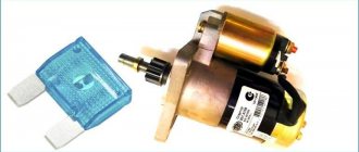
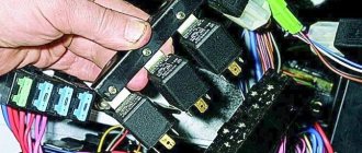
Their installation is easy. The fact is that in the block where they are located there is a special key, with which you can easily remove all the fuses, and put them in place by lightly pressing on them.
Photo 4
In order to remove and replace the control relay, you also do not need to make much effort. They have a fork at their base, and if you grab it with your hand and pull it up with a little effort, it can be easily removed. It can be put in place in the same way.
It is important to know that in the case of tuning a car, namely adding LEDs to the headlights, a situation may arise that all the fuses to which they are connected begin to blow out. In this case, experts recommend replacing them with resistors. You need to ask the specialist from whom the diodes themselves are purchased about which resistor is best. Installing the resistor itself will not be difficult, since its installation follows the principle of installing and removing a fuse.
Fault localization
Understanding the operating principle allows you to determine exactly why the brake lights may not light up:
The fuse has blown. In the diagram, the fuses are marked with the letter F (from English - Fuse) and the serial number of the seat in the fuse block, for example, F3;- poor contact at connectors;
- the light bulbs have burned out, but since the lights are connected in parallel, the likelihood that 2 lamps will burn out at once is extremely low;
- poor contact on the negative terminal of the lights. In this case, problems may begin not only with the feet, but also with the lighting of the remaining lamps in the lanterns;
- Damage to the negative track in the lamp board. From the total mass directly to the brake light lamp, the minus goes along a special path on the board. The path may collapse from water or mechanical impact;
- malfunction of the brake light switch, the so-called frog;
- broken wiring, oxidation of contacts.
Explanation of the additional fuse and relay block
To turn on the main systems of any car, the manufacturer has designed the installation of auxiliary fuses. As a rule, they are located in the center console area. Each auxiliary module consists of several important relays and fuses.
In this particular case, the box is located to the left of the glove compartment, behind the side trim of the center console. To quickly access the box, you need to remove part of the plastic protection. The protection is attached to Phillips bolts, so you need to prepare the appropriate screwdriver.
Location of additional fuse and relay box 2114, 2115, 2113
Additional unit in the cabin Diagram of the additional unit
Table 3. Explanation of the additional fuse and relay block
| № | Current, A | Purpose (Fuses) |
| 1 | 15 | Main distribution relay |
| 2 | 15 | Controller power |
| 3 | 15 | Fuel pump |
| № | Purpose (Relay) | |
| K4 | Fuel pump | |
| K5 | Cooling fan | |
| K6 | Main system control relay |
There are also options for other decryptions.
Explanation of the additional fuse and relay block
Relay:
Fuse:
f2 - main relay;
f3 - ECU (electronic control unit).
Relays that control the supply of current are present in the design of many vehicles. They are designed to perform a very important function - they turn on and off important electrical devices and mechanical systems of the vehicle. In simple terms, this is a device for supplying current to a required element.
How to troubleshoot?
The most common reasons that the brake light on the VAZ 2114 does not work are the following factors:
- Fuse failure.
- Broken wires in one of the sections of the circuit.
- Limit switch faulty.
- Bulbs burn out.
- Oxidation of contacts in lamp sockets.
- Damage to the contact board.
The most common and at the same time the most easily removable of the above reasons is a blown fuse. To identify such a malfunction, you need to examine the fuse box. A 10-amp fuse F3 is responsible for the brake lights, which also protects the ignition switch, computer and interior lighting.
Malfunctions in the operation of the latter may also indicate a malfunction of the stop fuse (and in this case, troubleshooting should begin with the block). If it turns out that the fuse has blown, then you should replace it with a new, similar one.
A new fuse installed in place of a failed one must be designed for exactly the same maximum current. If it is less, the fuses will blow more often, and if it is more, the protected device itself may burn out.
The problem may also be in the fuse block itself - sometimes the tracks on its printed circuit boards burn out or the contact legs oxidize. In order to check its serviceability, it is enough to measure the voltage at the contacts of the newly installed fuse.
How does the VAZ-2114 stove work?
The furnace equipment built into the VAZ-2114 operates according to the following principle. When turning the heater tap, the driver activates the supply of coolant or antifreeze. Antifreeze heated to 90 degrees is selected to the radiator; all that remains is to determine the fan rotation mode - here the driver is offered a choice of 3 formats at once.
After setting the desired position of the dampers, the air flow enters the interior of the VAZ-2114, and also blows on the windshield and legs. Without adequate fan operation, there can be no talk of any heating.
Warm air will be directed into the cabin too slowly, which is almost imperceptible for the driver and passengers of the car in the harsh Russian winters.
Malfunction of the lights themselves
If during the check from the fuse box to the limit switch no problems are found, then you should move on. Now you should test the wiring from the second limit switch connector to the stop connectors with a tester. If it is working, then you need to check the board. The printed circuit board on which the taillights are mounted is not ideal, and is one of the biggest problems of all VAZ cars.
Its tracks often burn out or peel off, causing the lights to stop working. This problem can be solved in two ways - either re-solder the tracks (which can be done with a regular soldering iron, although not in road conditions) or replace the board with a new one (most motorists choose the second option).
Another reason why the VAZ 2114 brake lights do not work may be oxidation of the lamp sockets. In order to eliminate this problem, it is enough to clean all contacts from oxides that have appeared on them.
This is best done in one of the following ways:
- small grit sandpaper;
- WD-40 solution;
- kerosene;
- purified gasoline (“galosh”).
You should absolutely not use gasoline or other solvents to clean contacts.
The last option for faulty stops is the light bulbs themselves. It makes no sense to give any detailed advice here - you just need to replace the burnt out light bulbs with new ones.
By following all the tips listed above, the car enthusiast gets the opportunity to check the entire electrical circuit of the brake lights, starting from the fuse box and ending with the bulbs in the lamps. Thanks to this, the guarantee that the fault will be accurately detected and eliminated is 100%.
How to replace the VAZ-2114 heater relay with your own hands
The ignition regulator, located in the VAZ-2114 directly under the instrument panel, cannot be repaired, it can only be replaced. The work of dismantling the old part and installing a new one does not require special knowledge, so follow the step-by-step instructions offered by the specialists, and soon the installation will be successfully completed:
- Disconnect the battery from the network by removing the terminal connected to the minus.
- Using a slotted screwdriver, unscrew the 4 screws located on the steering column housing. After this, removing the component will not be difficult.
- A Phillips screwdriver will allow you to unscrew another self-tapping screw holding the lower part of the case.
- If there are no fasteners, remove the protective housing from the steering block.
- At the bottom there is a block where the harness is located along with the wiring, and the VAZ-2114 heater relay is connected to them.
- Disconnect the adjuster from the block, carefully pull it out and install a new part.
- Assemble the structure together, returning the fasteners to their original place. Check how the heater now works and whether heated air enters the car interior.
Additional Tips
Before each trip, especially over long distances, you should check the functionality of all lighting equipment, including brake lights. In order to reduce the likelihood of breakdowns along the way, you need to periodically check the condition of the sockets and bases of the rear light bulbs, and periodically clean them of oxides and dirt.
In case a breakdown does occur, you should always have an additional set of light bulbs and 10 amp fuses in your car, as well as a multimeter to check them.
Car electrical equipment
The electrical equipment of a car (another name is the electrical system of a car) is designed to generate electrical energy and power various systems and devices of the car.
The electrical equipment of a car combines current sources and consumers, controls, and electrical wiring. All structural elements of electrical equipment are integrated into the on-board network.
The sources of current in a car are the battery and the generator.
The battery is designed to supply consumers with electric current when the engine is not running, when the engine is started, and when the engine is running at low speeds.
The main source of electric current is the generator. It provides electrical power to all consumers, as well as charging the battery.
The capacity of the battery and the power of the generator must correspond to the power of electricity consumers in all operating modes of the vehicle, i.e. Energy balance must be maintained in the system.
Energy consumers can be divided into three groups: main, long-term and short-term. The main energy consumers ensure the vehicle's performance. These include: fuel system, injection system, ignition system, engine management system, automatic transmission, electric power steering.
Long-term consumers are the cooling system, lighting system, active safety systems, passive safety systems, heating and air conditioning systems, anti-theft systems, audio systems, navigation systems.
Short-term consumers include most comfort systems, starting system, glow plugs, horn, cigarette lighter.
Control elements ensure coordinated operation of current sources and electricity consumers. The system uses the following control elements: fuse panels, relay blocks, electronic control units. They are located, as a rule, decentralized.
On modern cars, many functions of relays and switches are assigned to electronic control units, but it is not yet possible to completely abandon these devices. For example, the on-board network control unit is assigned the following functions:
- energy consumption control;
- monitoring the voltage at the battery terminals and, if necessary, increasing the engine speed at idle;
- load regulation by disconnecting individual consumers, mainly from comfort systems;
- control of the lighting system, windshield wipers, rear window heater, etc.
In addition to traditional electrical wiring, the vehicle's on-board network uses multiplex systems - the so-called. data buses that ensure the connection of electronic control units with each other and the transmission of control signals in digital form.
How to check wiring
You can diagnose electrical equipment using a voltmeter, ohmmeter or multimeter, or special diagnostic stands. Computer diagnostics are also carried out, during which error codes and main indicators of the machine’s on-board network are read. To independently check circuits and troubleshoot electrical faults, one multimeter or signal lamp is enough.
We use a multimeter
Fuses in the on-board network are considered the “weakest” link in terms of durability. In case of emergency situations (for example, in the event of a short circuit), the safety elements “take the blow”, protecting the rest of the electrics and electrical equipment of the machine. Fuses cannot be restored and must be replaced during repairs.
Checking the voltage
Before checking the wiring in the car, it is necessary to measure the voltage of the electrical circuit between individual components and electrical equipment. You can call like this:
- Set the multimeter to voltmeter mode.
- Connect one probe of the measuring device to the “minus” of the battery or to the ground of the machine.
- Connect the second probe to the supply wire of the circuit.
If a certain value appears on the device display, then there is voltage in this section of the electrical circuit. You can compare the values with those required according to the vehicle's owner's manual.
Looking for a short circuit
After measuring the voltage, search for short circuits. This will require either a multimeter or a pilot light. As for the lamp, if the wiring is in good condition and there is no short circuit, it should not light up.
A short circuit in the wiring, as well as a lack of voltage (zero or infinite resistance in the electrical circuit), indicates a malfunction in one of 2 components:
- Consumer - electrical equipment, devices, fuses, blocks.
- Wiring – broken or shorted wires, poor wiring contacts at the point of connection with the consumer.
Checking for a short circuit can also be done in voltmeter mode. To do this, it is necessary to remove all fuses in the area being tested and connect the probe to the terminals of the fuse element. The value “0” on the screen indicates the presence of a short circuit in the circuit. If, when you try to move the wires, voltage appears in the circuit, then the short circuit is caused by the wiring and the wires will need to be replaced.
Checking the quality of grounding
Cars use a single-wire wiring diagram - this means that the “minus” goes to the ground (body) of the car. However, corrosion of metal parts, their oxidation and destruction, “loosening” lead to grounding failure and, as a consequence, to disruption of on-board circuit contacts.
Read more: Transmission oil for walk-behind tractor Neva MB 2
Checking the grounding, as well as other electrical elements of the car, is carried out using a multimeter. The procedure is as follows:
- Disconnecting the battery.
- Connecting one multimeter probe to the body (metal parts) of the car.
- Connecting the second probe to the grounding element or wiring connection.
The value displayed on the device screen should be compared with the factory data (car operating manual). If the values diverge greatly, then it is necessary to restore the grounding - clean the metal at the connection point, check the reliability of the fastening.
Checking the integrity of the circuit
The connection of wires in the electrical circuit of cars is one of the most vulnerable points in the entire electrical system of the car. In addition to the destruction of insulation, loss of integrity and breaks at the connection points, oxidation of the contacts also often occurs here. Defects can be determined not only using a measuring device, but also visually. If the integrity of the circuit is broken precisely at the connection point, then soldering of wires with connectors will be required. Otherwise, you need to find the damaged area, which will require a signal lamp or multimeter.
Starter, ignition, rear fog lamp relay
In order to carry out quick checks and repairs, the ignition system relay is installed under the front dashboard of the car, behind the hood release handle. It is located just below the central dashboard. The module is closed with a plastic plug, which must be opened slightly to test for functionality.
Starter, ignition, rear fog lamp relay
Next to the indicated relay, there is a similar one for the rear fog lights and the starter.
The main task of the relay when igniting is to reduce the applied load to the contacts. When the engine starts, the relay turns off some electrical circuits in the vehicle system. The system is used not only in injection, but also in carburetor engines.
In the event of a malfunction or malfunction in the ignition system, it is necessary to monitor the operation of the relay. For this purpose, open the box and carefully remove the desired element. It is attached using contacts to special grooves. The first thing to do is look at the oxidation of the contacts, if necessary, clean them with a soft cloth or treat them with a special liquid.
To check functionality, you need to use a regular multimeter. We connect to incoming connections and check the numbers. If there is no short circuit when current is applied, it means the element is not working. Replacement is carried out in a similar manner. It is necessary to use a standard element with the number of amperes indicated on the housing.
Use the second wrench as leverage
If you are trying to unscrew a stuck/rusted/oxidized bolt or nut and are unsuccessful, stop for a second and remember Archimedes, who said the great phrase: “Give me a fulcrum and I will move the Earth.” This means that the task is simplified. Remember, the torque required to remove a bolt or nut is equal to the force times the distance. So why go out of your way to increase “power” when you can simply increase “distance”?
Take the second wrench and put it on as shown in the photo. That is, put it on the end of the first key to get one large lever. We twist the bolt/nut, but try not to overdo it.
How to unscrew the caliper nipple?
When swaying the brakes, usually all people have the same algorithm of action. First, a hose is put on the caliper nipple, then the nipple itself is released with an open-end wrench. But what to do if the nipple doesn’t want to budge? It is better to use a socket wrench for these purposes and here's why:
If your brake caliper nipple is soured and you try to unscrew it with a regular spanner/open-end wrench, you are making a mistake. The surface area of these wrenches is small, but the risk of tearing off the edges on the nipple is unusually high.
It is much safer to use a socket wrench instead. With a long handle. We treat the stubborn guy with penetrating lubricant, let the oxides loosen their grip, and carefully loosen the nipple. The brakes are ready to be bled.
This is another sound piece of advice to add to your knowledge base. Since the nipples on the calipers, as we all know, are made of soft material and even the slightest turn of the spanner can tear off the splines, forcing you to resort to using pliers. Any use of materials is allowed only if there is a hyperlink to 1GAI.ru
Reworking the relay circuit
The number of LEDs installed in series can be determined experimentally, but in practice 5 pieces are enough: such a load is quite enough to trigger the circuit. At the same time, the circuit on the board opens, which allows it to work with both conventional and LED lamps. However, in this case, the device will not be able to signal that the turn signal bulb has burned out.
The refinement algorithm is considered using the example of a relay that operates using a U643B controller manufactured by the Chinese company Atmel. Such controllers are often used in electronic equipment circuits of modern passenger cars.
One of the functions of such a controller is to warn of a malfunction of the turn signal bulbs. The criterion for malfunction is a critical decrease in the current in the circuit, as a result of which the blinking frequency increases sharply.
Electronic turn signal relay circuit for LEDs
The operating value of the LED current is set at the output of the “Lamp failure detection” controller circuit. The nuance is that the efficiency of LED lamps is much greater than that of conventional lamps. The inconvenience is that the current consumption is reduced, and increased flickering of the LEDs is perceived by the controller as a malfunction of the turn relay.
In order to get rid of this drawback, you simply need to replace resistor R3 of the circuit with a more powerful one. This will lead to an increase in the total load, and a corresponding increase in the current strength - to values at which the turn signals will no longer blink.
An alternative solution for some car enthusiasts is to cut out the section of the circuit in the circuit that is responsible for measuring the current. However, this action also reveals a serious problem.
Since the U643B controller works with its initial parameters already set by the manufacturer, with such “tuning” of the turn signal, you can accidentally change the so-called Device Code - the controller identification code by external devices. It is impossible to reflash it. In addition, by cutting out one of the contacts in the turn signal relay circuit, you can get frequent blinking of the turn signals, which does not always satisfy the car user.
Reverse restoration will most likely not yield anything, since the relay controller has already “remembered” its new parameters and changed the Device Code.