Removing and installing a caliper on a VAZ 2114-2115
The front brake calipers on the VAZ 2114-2115 have to be removed quite rarely, and replaced even less often. But there are cases when the clamping bracket mounting bolts rust so badly that when unscrewed they simply break off. Many people do not drill and replace the caliper with a new one. In order to remove it from the car, you will need the following tool:
- Head 19
- Driver and ratchet handle
- extension
- brake pipe wrench
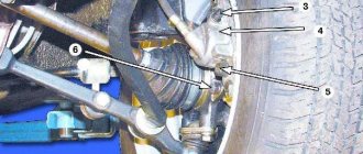
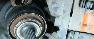
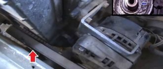
So, after the car is jacked up and the front wheel is removed, it is necessary to spray the caliper mounting bolts with penetrating lubricant from the back side. Then you should unscrew the brake hose, as shown in the photo below:
Lift it up and secure it so that the brake fluid does not leak out of the reservoir. Now you can unscrew the two caliper mounting bolts:
When the effort is not so great, it is better to use a ratchet:
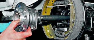
After this, you can lift the caliper assembly with pads up, since nothing else holds it.
If you are changing the entire assembly, then buy a new mechanism and install it in the reverse order. After this, you will have to bleed the brakes, as air may form in the system, which will lead to poor braking.
Source
Examples of prices for current items
When buying a caliper for a VAZ 2109-2115, you can operate with the available amount, since there are quite a lot of good quality analogues to choose from, namely:
- Caliper assembly, R13 TRIALLI – RUB 1,880 .
- ATE assembled with a ventilated moving bracket – RUB 2,480 .
- LUCAS with an extended hose (without adapter) – RUB 4,050 .
- LADA (standard set for R13 wheel) – 4,270 rubles .
The choice of calipers is represented by more than 17 analogues, 2 original brands and 3 brands operating under AvtoVAZ license. Consequently, the price may change based on the financial policy of the manufacturer, as well as the final cost of the caliper.
Removing the caliper VAZ 2114
Removal and installation
Withdrawal. Raise the front of the car and place it on stands and remove the wheel. Unscrew the pipeline fitting and disconnect the flexible hose from the line; Plug the holes in the hose and tube to prevent brake fluid from leaking. Remove the hose from the guide bracket.
After unscrewing the two bolts that secure the shoe guide to the steering knuckle, remove the guide assembly with the caliper and working cylinder.
Installation of the brake mechanism is carried out in the reverse order of removal. After installation, restore the brake fluid level in the reservoir and bleed the hydraulic drive system to remove air.
Disassembly and assembly
Rice. 6-20. Unscrewing the cylinder mounting bolt: 1 – cylinder mounting bolts; 2 – cylinder; 3 – bolts connecting the cylinder with the caliper
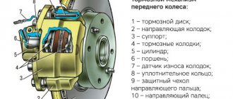
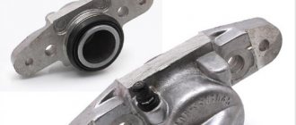
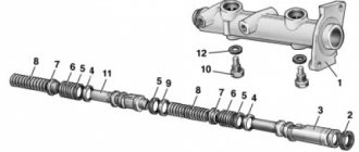
Rice. 6-21. Parts of the front wheel brake mechanism: 1 – wheel cylinder; 2 – fitting for bleeding the brake drive; 3 – sealing ring; 4 – piston; 5 – protective cap; 6 – retaining ring; 7 – caliper; 8 – pad guide; 9 – brake pads; 10 – protective cover; 11 – guide pin; 12 – guide pin fastening bolt; 13 – brake hose; 14 – bolt securing the cylinder to the caliper
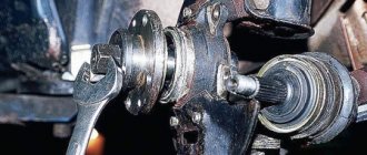
Disassembly. Disconnect the hose from wheel cylinder 2 (Fig. 6-20). Unlock and unscrew bolts 1 securing the wheel cylinder to the guide pins, holding the guide pin by the edge with a wrench. Remove guide 8 (Fig. 6-21) of the pads and pins. Remove the brake pads 9.
WARNING. Do not unscrew bolts 3 (see Fig. 6-20) connecting the caliper and cylinder, except when replacing the caliper or cylinder.
Remove the retaining ring 6 (see Fig. 6-21) and the protective cap 5 from the cylinder and piston. Carefully push a stream of compressed air through the fluid inlet to push the piston out of the cylinder. To avoid damaging the piston on the surface of the caliper when pushing it out, install a wooden pad under the piston (Fig. 6-22).
Unscrew the bleeder fitting from the cylinder body and carefully inspect the working surface of the cylinder. There should be no scoring, damage or corrosion.
Rice. 6-22. Pushing the piston out of the cylinder
Assemble the brake mechanism in the reverse order of disassembly. In this case, it is recommended to replace sealing ring 3 (see Fig. 6-21) and cap 5 with new ones. Lubricate the cylinder mirror, piston 4 and the sealing ring with brake fluid, and apply graphite grease or Ditor grease to the surface of the piston, install the piston in the cylinder and, without removing any remaining grease, put on the protective cap 5 so that its edges fit into the groove of the piston and cylinder, then install retaining ring 6. Lubricate the guide fingers with UNIOL-1 grease (1.5 g for each finger). Tighten the bolts securing the caliper and cylinder to the pins to the torques specified in Appendix 1, then lock them. Before tightening the bolts, apply sealant to them to prevent corrosion of the threaded part of the connection. After assembling and installing the brake mechanism, restore the fluid level in the reservoir and bleed the hydraulic drive system.
Malfunctions
Any driver experiences an unpleasant feeling when the clutch pedal sinks to the floor. This can happen if the clutch cable breaks; it is also possible that the release fork breaks (this case is discussed in another article). The cable breaks more often on older cars that are used in extreme conditions or all year round.
The cable may become frayed, which affects the smoothness of the pedal and the operation of the clutch. This cable also requires replacement.
If the clutch cable is broken, you can drive your car to the repair site. You need to start the car in first gear and shift while driving. The following situation is possible: the cable broke while the gear was engaged, and the car stalled.
There is a possibility that it will be difficult to engage the neutral position. Then your car won’t even be able to roll off the roadway. The transmission is disengaged by rocking the car forward and backward and disengaging the transmission at the same time. You can jack up one of the wheels and spin it by hand, this will also help.
Even if the cable is not replaced, gear shifting is possible. It is possible to get to the service station, but such driving has a negative impact on the service life of the gearbox.
The cost of the spare part is low, about 300 rubles. The cost of replacing a cable in a car service is 400 rubles.
Installation details and purchasing spare parts
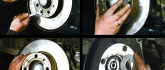
So, it's time to start installation. The first step is to unscrew the brackets, cylinders and guides. Typically, new discs have a large central hole (CO), and therefore, for correct operation and accurate centering, I would advise cutting a strip from a tin beer can, which must be inserted between the hub and the disc to eliminate play. After this operation, you can put on the disc and screw on a new bracket. Diagnostics of the car's brake system must be performed without fail.
Simple step-by-step instructions for installing rear disc brakes
Step 1
We loosen the tension of the cables and bring the rear pads together, then use a 12mm wrench to unscrew the guide pins. Use a metal brush to clean the seat and carefully knock down the brake drum. I recommend using a rubber mallet to avoid damaging anything. Truly super tuning of a VAZ 2114 car requires patience and strength. Using a screwdriver, pry up the spring that tightens the pads and remove it. We pull out the spacer bar and take out the upper tension spring. After this, remove the brake pad, first lowering the handbrake lever.
Step 2
When all the old parts have been removed, you can begin installing the HCD. Decide how you want the caliper to be placed - behind or in front of the axle. The effectiveness of the brakes will not change in any way from this operation. I put the axles behind. This is more symmetrical and the weight of the brake mechanism will help with braking. Now you need to join the hub and faceplate into one piece. This operation should be taken seriously. It will be useful to watch a video on this issue, where domestic masters show their tuning of Russian cars in order to share their experience and show some of the intricacies of performing this work. The centering process must be carried out very carefully.
Step 3
Now you can straighten the corners of the beam before placing the hub combined with the faceplate on the beam. This must be done so that the corners do not interfere with the caliper. Personally, I flattened them with a hammer. This work can also be done using a grinder. You should not install a grinder under the left hub bolt, otherwise you will have to work with the grinder again and file the head of the bolt. The brake caliper bracket may rest against it.
Step 4
Well, now the most important thing. We install the bracket on the faceplate and put the brake disc on the hub. Place spacers at the connection points. This must be done at connection points. It happens that the size of the washers may differ, then you need to buy them for a specific car, in our case it is tuning a 14 model car. We tighten the faceplates and the connection of the brackets (I recommend doing this with a force of 3-4 N.M). We screw the hose to the caliper, install the pads, and you can close the tube sealing line. Now we seal the brake line. We check the line for leaks by pumping up the pressure with the pedal. If everything works as it should, then you can begin installing the HCD on the other side.
Source
Purpose of the timing belt
An internal combustion engine is a complex system that consists of hundreds of parts and several more or less independent mechanisms. And the engine will only function normally if its mechanisms, assemblies and systems work in harmony. This quality - consistency of operation - is of decisive importance for the engine. For example, a certain position of the pistons corresponds to a strictly defined position of the valves, and if this condition is not met, the engine simply will not work.
Therefore, in internal combustion engines there is an urgent task of synchronizing and coordinating the operation of several systems. In modern engines, this problem is solved using several drives - a gas distribution mechanism drive, a generator, a water pump, an ignition distributor, a fuel pump, etc. But the most important thing is the timing drive, which is necessarily present in all types of engines.
- 1,050 rub.
- 350 rub.
- RUB 3,785
- RUB 1,190
- 415 rub.
- 300 rub.
- RUB 2,070
- RUB 3,350
- RUB 1,135
The engines of VAZ passenger cars initially used a timing drive, implemented using a metal chain that connected the crankshaft gear to the timing shaft gear and some other units. However, later VAZ designers abandoned the use of a chain, preferring a simpler, more reliable and modern solution - a rubber timing belt.
The timing belt in VAZ engines solves several problems at once:
- Transmission of torque from the engine crankshaft to the shaft (or shafts, if there are two) of the gas distribution mechanism;
- Transmission of torque to auxiliary units, primarily to the water pump of the engine cooling system;
- Ensuring synchronous operation of the crankshaft and timing gear;
- Preventing mismatch between the operation of the crankshaft and timing gear in all engine operating modes.
It should be noted that in VAZ cars the timing belt serves to drive the camshafts and water pump. This belt could, in principle, rotate the generator and other mechanisms, but VAZ designers abandoned this idea. Why? Because in this case, a broken belt or jamming of any of the units would immediately disable the entire engine, so it is more reliable and safer to make a separate drive for some units. And a breakdown of the water pump will not stop the engine immediately, so combining the drive of this unit with the timing drive does not pose a potential danger.
VAZ cars use several types of timing belts, which differ in characteristics and design.