One of the very relevant topics for domestic motorists is how to correctly set the ignition in a car using a strobe light. Agree that only a few experienced drivers and mechanics are fluent in this technique. For those who are familiar with it only by hearsay, experts recommend that you familiarize yourself in detail with how exactly a strobe functions, what its key characteristics are, how to independently make a device for such an installation, and, finally, what is the practical algorithm for adjusting the ignition using the device. This will help them prevent excessive fuel consumption, unreasonable engine overheating and other undesirable phenomena that negatively affect the operation of the machine and shorten its service life.
How to operate the device?
By assembling the device according to one of the given diagrams, you can simply and easily, and most importantly, accurately adjust the ignition on carburetor engines, check the correct operation of spark plugs and coils, and control the operation of the advance angle regulators.
To set the ignition as correctly as possible, it is usually assumed that the mixture is ignited a couple of degrees before the piston reaches the highest point. This angle is called the "lead angle". As the crankshaft speed increases, the angle should also increase. So, this angle is set at idle, and then it is necessary to check the correct setting in all operating modes of the unit.
The principle of creating the device
A strobe light for ignition adjustment is especially necessary for those who have a car with a carburetor. This is due to the peculiarities of the settings, since it is difficult to imagine correctly even in the mind, not to mention in reality, the ignition timing, which is present on contact distributors and all contactless distributors. It is simply impossible to cope in such a situation without a strobe light. Moreover, by using the services of this most precise device, you can adjust the ignition with extreme precision in just 7–8 minutes. This indicator, like other important elements of the car, must be given due attention, since without it the normal functioning of any vehicle is impossible. The need for such a product, the high cost of the factory version in the store and the availability of the necessary parts simply push a person to create his own strobe light.
Doctrine on fuel assembly combustion
How to check the ignition timing
As many people know, fuel assemblies do not burn completely after ignition. Or rather, it burns out, but not immediately. Moreover, it does not detonate in the engine cavities, as some amateurs believe. The combustion of gasoline is a chemical reaction that has its own speed. And you need to be able to coordinate it with the speed of the piston stroke. This is the method of obtaining the most optimal gas pressure at the required point.
The combustion of fuel assemblies is not just a chemical process, but a whole theory. For example, if you delve into the jungle of this area of science, it becomes clear that with a small spark from a candle, the front of the flame begins to spread. The spark burns for approximately no more than 1 millisecond, and during this insignificant time the temperature reaches the highest Celsius level - 10 thousand degrees. The volume of flammable material that receives the first charge is essentially instantly destroyed. And from this heat the flame front is transmitted throughout the entire chamber (CC).
It has been proven that the initial combustion rate is negligible. But as the flame increases, the speed increases by 70-80 times. Remains of fuel assemblies, which do not disappear completely due to the fact that they are located near the less cooled walls of the combustion chamber, burn out noticeably more slowly. Thus, the entire combustion process takes approximately 30 degrees UPKV (rotation angle of the crank shaft).
At different positions of the SPD, correspondingly different flows occur inside the engine. If the angle is set correctly, the ignition is not disrupted, then the optimal pressure of gases is delivered to the place where the piston passes TDC. According to the degrees scheme – 10-12°.
If the OZ deviates, for example, towards delay, then the most optimal gas force maintains the 45 degree zone, which implies a lower position of the piston. It turns out, as we see from the diagram, that the gases seem to be sent after the piston going down. The efficiency of such piston operation is reduced to almost zero.
It is in such cases, during the process of late ignition, that the fuel assembly burns out after the exhaust valves open. And the hot gases of the exhaust system can easily ignite only the approaching charge of the mixture. This is what causes the popping sounds, which are sent to the air flow distributor.
Article on the topic: Do-it-yourself refilling of the car air conditioner
An unfavorable situation also occurs with early ignition. In this case, the apogee pressure level occurs at TDC or earlier. The gases begin to put pressure on the piston, which has not yet reached its apogee. Obviously, this option will not lead to anything good - the power of the internal combustion engine will noticeably decrease, detonation and other troubles will occur.
DIY strobe light diagram for a car
One of the most important conditions for proper operation! car gasoline engine is the correct setting of the ignition timing. In VAZ car engines, the ignition timing is set using four marks - one on the crankshaft pulley, and three on the block body. Usually, a rather cumbersome device is used to adjust the ignition. -strobe light For power supply, the strobe is connected to the car battery, and the third wire. - to the spark plug wire of the first cylinder. When the engine is running, the strobe lamp flashes every time. as soon as a high voltage pulse arrives at the spark plug of the first cylinder. The pump light is directed to the marks. As a result of the synchronous flashing of the lamp, we see four marks - three on the block and one on the pulley, which seems motionless to us. The relative position of these skeins determines the correct installation of the ignition (the mark on the pulley should be opposite the middle mark on the block, if this is not the case, you need correct by turning the distributor housing).
A standard strobe is a rather bulky, heavy and fragile device, mainly due to the gas-discharge pump and pulse transformer it contains. But, using a modern element base, you can make a strobe a little larger than a ballpoint pen.
Figure 1 shows a diagram of a strobe light in which a 12V LED car light bulb operates instead of a gas-discharge pump (nowadays it has become fashionable to install such LED pumps in sidelights instead of incandescent pumps).
Rice. 2.
The device is connected to the vehicle systems using three wires with crocodile clips. Two are to the battery, and the third is to the wire of the 1st cylinder. The third “Crocodile” (connected to the spark plug wire) has been slightly modified. — its “teeth” are bent inward so as not to spoil the spark plug wire, and it rather resembles a metal clothespin.
As soon as a high voltage pulse arrives at the spark plug of the 1st cylinder, through the capacitance between the core of the spark plug wire and the body of the “Crocodile-clothespin”, a voltage surge is supplied to pin 2 of element 01.1 (zener diode VD1 protects the input of the element from overvoltage) Single vibrator based on elements 01.1- D1.2 will generate a pulse whose duration is about 1 mS. This pulse, through a buffer cascade on elements 01.3 and 01.4, is supplied to the base of transistor V11, which is part of the pulse switch VT1-VT2. The key opens and the LED light HL2- flashes
Now about the details of circuit C1. R1 and R2 are soldered directly into the “Crocodile” handle, which is connected to the spark plug wire.
Connecting cable. — soft shielded, no more than 10 cm long. For connection to the battery. - ordinary wires, as for “carrying”, of any length (within reasonable limits). Diode V02 is used to protect the circuit from accidental power reversal. LED HL1 is an indicator of correct connection to the battery.
The basis for the device was a cylindrical Chinese pocket flashlight. All its “internals” (switch, light bulb, batteries) were removed, leaving an empty body and a conical reflector. The base of the reflector is slightly widened so that it can accommodate an LED car light bulb. The case contains a printed circuit board (Fig. 2) on which most of the parts are mounted. The housing has holes drilled for connecting wires and the HL1 LED.
Trimmer resistor R4 is used to set the duration of the HL2 flash such that
in which the mark on the rotating pulley of a running engine is visible stationary and not smeared, but visibility remains sufficient.
If the device does not respond to impulses in the spark plug wire to which the “Crocodile-clothespin” is connected, and begins to respond only when the “Crocodile” is strongly compressed, you need to increase the resistance R2.
Instead of an LED light bulb, you can use a regular super-bright LED by connecting it through a resistor with a resistance of about 10 Ot. But using a strobe will not be so convenient, because due to the lower brightness of the light, it will need to be placed closer to the marks on the engine.
Tags
Description of the strobe
How to make a simple strobe for setting up an OZ on LEDs, what elements will the circuit of the device consist of? First, let's look at the main characteristics of the device.
Working diagram
The main constituent elements using the example of the above diagram:
The power circuit consists of switch SA1, diode element VD1 and capacitor device C2. The diode is used to protect other components from erroneous polarity reversal. The capacitor itself is used to block possible interference, thus preventing failure of the trigger
The purpose of switch SA1 is to activate and deactivate power. An equally important component is the input circuit, which includes the controller, resistor elements R1 and R2 and capacitor device C1. The role of the controller here is played by the device clamp, which is called a crocodile, it is fixed on the high-voltage wire of the first cylinder
If the connection is correct, then the above elements form a simple differential circuit. Trigger circuit. This component consists of two single vibrators used to generate a signal of the desired frequency at the output. These components perform the function of frequency setting. The output stage is made using resistor elements R5-R9, and transistors VT1 are also used for this purpose. VT2 and VT3. These devices are necessary to increase the output current of the trigger board. The resistor device R5 sets a certain base current of the transistor element number 1 (the video was shot by Maxim Sokolov).
https://youtube.com/watch?v=66UN9BAWN0A
Operating principle
The device for setting the advance angle is powered by a built-in battery or car battery. When the switch is activated, the trigger starts working first. At outputs 2 and 12 of the board, an increased potential is formed, and a low potential is formed at pins 1 and 13. At this moment, capacitor parts C3 and C4 receive power from resistors.
The signal from the controller goes through the differential circuit and is ultimately supplied to the DD1.1 input. Since it is a one-shot device, it results in switching of the device. Then C1 is overdischarged in the circuit, which again contributes to switching the trigger.
Element DD1.1 will respond to pulses supplied from the controller, thus generating new rectangular pulses at the first pin. In the case of the second one-shot DD1.2, the principle of operation will be identical - thanks to this device, the pulse duration at pin 13 is reduced by 10 times. This element operates under a load supplied from the amplifier stage of transistors, which open for the duration of the pulse. Thanks to the resistor components R6, R7 and R8, the current is limited, its value in total should not exceed 0.8 amperes.
The current value is not high, this is due to the following factors:
- the pulse duration is no more than 1 second;
- Usually, car owners need no more than 10 minutes to set up the OZ; during this time the crystals will not overheat;
- diodes used today have improved performance and features when compared to devices used more than 10 years ago.
Printed circuit board and assembly parts
In order to build a strobe light with your own hands, you will need a board with all the necessary elements.
As an example:
On the board we are considering, the diode function is performed by the KD2999V controller. In principle, you can use any other one, you just need to take into account that the diode element must have a minimum voltage drop. Capacitors are also used
It is important that they are rated at 0.068 µF. As for the main capacitor device C1, it is a high-voltage part, the voltage of which is 400 V. The trigger device - TM2 - has excellent resistance to possible interference. It is necessary that the transistors used VT1, as well as VT2, have a high gain. As for the diodes marked with the symbols HL1-HL9, they should have maximum brightness, and it is also desirable that the dispersion angle be small
Diode components are mounted on a separate circuit; their number should be 3 in a row.
Creating a strobe light on a chip
The simplest strobe for installing the ignition is to create a device that is based on the DD1 microcircuit, which is a single-vibrator. Several diodes are connected to this microcircuit, which help protect it from possible errors that occur during connection. Before the next pulse hits the microcircuit, it is in its usual quiet state. The system is equipped with two different pins, with the first having a low level, which is opposed by a high inverse pin. Accordingly, the connected capacitor is connected with a plus to the inverse terminal, due to which it is charged. A pulse passing through the entire microcircuit “hooks” a trigger, behind which a charged capacitor is connected to operation. The entire process takes place directly through the resistor. The soldered-in DD1 chip responds to the electric current supplied to it, displaying the energy through the glow of LEDs.
>How to properly connect a car strobe light?
Everyone knows that not only the stable operation of the entire engine, but also fuel consumption depends on how correctly your ignition timing is set.
In order to install a car strobe light not on LEDs, but one that is intended for installing the ignition and installing the UOS, you should start the engine at idle and begin to illuminate the special installation marks with the strobe light.
One of them is movable, that is, located either on the crankshaft, or on the flywheel, or on the generator drive pulley, the other is located on the engine body itself.
The capacitive sensor must be attached to the high-voltage wire of the spark plug of the first cylinder so that the flashes are synchronized with the moments of spark formation in the spark plug. Thanks to the light from the flashes, both marks can be seen. If they are located one against the other, it means that the ignition timing is set ideally; if there are small offsets, the position of the distributor-distributor should be adjusted until the marks coincide.
Now let's take a closer look at the procedure for tuning a car engine using a strobe light.
First, take the car out of the garage. Inspect the strobe, carefully checking to see if there is any mechanical interference. It is best to carry out this procedure in the evening, or in cloudy weather, because direct rays of the sun can create light interference, which will prevent you from using a strobe.
Then, turn off the engine. When connecting the device to the battery, use clamps and be sure to observe the polarity(!). Incorrect connection of the contact wires will lead to a short circuit! Carefully read the instructions supplied with the device in order to avoid this.
In order to form a capacitive coupling with the device, it is necessary to attach the signal cable connected to the spark plugs of the first cylinder to the wire.
Arrange the wires so that they do not get caught in any rotating parts of the machine.
Locate the white mark on the crankshaft pulley or flywheel. After this, identify the same marking on the power unit housing.
Don't forget to follow safety regulations. First, remove all metal objects from yourself, and then set the gear shift lever to neutral.
Wear dielectric gloves. Avoid all possible contacts of body parts and clothing items with moving mechanisms. Start the car and let it run until the idle speed stabilizes.
Loosen the mounting bolt that prevents the distributor from turning.
Next, take a strobe light and point its lamp at the crankshaft pulley. This way you can illuminate the mark on the housing and the mark on the engine.
Slowly turn the distributor body; you are required to achieve maximum coincidence of the marks, as we said above. If the marks match, turn off the engine and turn off the strobe. By tightening the mounting bolt, secure the distributor body.
Well, now, you can start testing the car and checking the correct ignition adjustment. To do this, you will need to accelerate the car on a flat section of the road to 50 km/h, and then sharply press the gas. If you hear detonation knocks that last no more than two seconds, you can be sure that you did everything right and deserve a rest.
Using the device
To set the advance angle (moment) with your own hands, use a device to illuminate the setting marks while the car engine is idling. One of them is located on the rotating parts of the car engine (on the crankshaft pulley or on the flywheel). The second mark is stationary, it is located either on the cover of the front part of the car’s cylinder block, or on the gearbox housing. If in the light of the device the movable mark appears to be opposite the stationary mark, the car’s ignition is normal and does not require adjustment of the timing (angle) of advance.
If the marks do not match, to adjust the timing, you need to change the position of the distributor accordingly. To delay the ignition timing, you need to turn the distributor in the direction of rotation of the slider, and to do it earlier, in the opposite direction. If sparking in your car is controlled by a microprocessor, look for a faulty sensor or entrust the solution to this problem to professionals.
With a strobe light, setting the ignition on a carburetor engine is always much more convenient than “by ear”. But the price tags for such equipment sometimes “bite,” which pushes many motorists to alternative solutions to this issue, for example, by making a strobe light with their own hands.
Ignition setting device made of LEDs
This device can be made using LEDs, but this strobe contains a specific microcircuit. It is launched through pulses that contain negative polarity. There are certain resistances in the structure of this type of circuit; they serve as limiters in order to reduce the amplitude of the incoming signal. In this case, the car battery will serve as the power source for the device itself.
Connecting the strobe light that sets the ignition is done using the following steps:
- you need to warm up the engine and leave it on;
- connect the handmade device to electricity;
- wind the sensor onto the cylinder wire;
- direct the light to a specific point located in the body;
- wrap the ignition housing until these marks come together;
- fix it in this state.
A homemade strobe for setting the ignition is not inferior in function to devices made at the factory. In this case, the main factor is to follow all manufacturing instructions and adhere to the diagram of the DIY device. Products made from scrap and simple materials may require little investment. Homemade strobes are fairly easy to repair if they become worn or broken.
The ignition installation device can be found in any specialized store; there are several types of them and they are quite common. However, the cost of this device often scares off vehicle owners, because it is not a cheap pleasure.
In the event of a malfunction or breakdown that occurs over time, replacing the worn part can be equal to the cost of the entire device itself. That is why car enthusiasts began to make strobe lights with their own hands. After all, to create it you will need parts that can be found in any store.
It is worth noting that a homemade device will cost several times less than a factory device. If you can’t make the device yourself, you can always find a craftsman who will do this work. Such specialists today work in almost every locality.
Making your own strobe light will save you a fair amount of money.
Introduction
It's no secret that many problems that sometimes arise with a car can be corrected even by a novice car owner.
Despite the apparent complexity of the mechanism, sometimes you can avoid another visit to the service center or the purchase of another unit for replacement. Anyone who wants to save money on purchasing a low-quality device can independently make, for example, a strobe light, which is designed for installing an ignition. Many beginners may be put off by the name, which seems too complicated and pretentious, but don’t rush to conclusions. To know how to make a strobe light for installing the ignition without purchasing an identical factory device, you should familiarize yourself with several proposed methods and stock up on all the necessary materials and tools. For those who are not confident in their abilities, it will be enough to go to a car store at least once and find out about the cost and quality of a production strobe light. In fact, almost the majority of car owners resort to using conventional gas-discharge lamps to create this cunning device. True, such devices cannot be distinguished by long-term operation, especially since the cost of a lamp that once fails is not very different from the amount for which you can purchase a new strobe light. All this together can prompt a car enthusiast to create his own device. Let's look at the simplest and most accessible methods of creating a strobe.
Average price of a factory product and its disadvantages
The factory version of the device has some disadvantages that significantly reduce the usefulness of such an acquisition.
It is always more convenient to set the ignition on carburetors with a strobe light
Firstly, the cost of factory stroboscopes is quite considerable. So the digital model Multitronics C2 will cost the buyer about 900-1000 rubles. The more functional AstroL5 strobe will cost 1,300 rubles. Focus F1 - a model suitable for servicing both gasoline and diesel engines - will require 1,700 rubles, its more “advanced” brother Focus F10 - 5,600 rubles.
Secondly, manufacturers often use an expensive gas-discharge lamp in the design of their products. It has a limited resource and may require replacement after a short time, which will not only hurt your pocket, but will be tantamount to buying a new strobe light.
"Advantages" of factory devices
Before you decide to purchase a standard factory strobe, you need to study in detail all its features and learn about the principle of operation. So, let’s first understand the scope of application of this device. A device called a strobe light allows the car owner to easily adjust the ignition. Having this device at hand can significantly speed up the entire setup process. Equipped with a lamp, the unit gives signals about the presence of a spark, so you can quickly and correctly set the required ignition timing.
It is impossible not to note the efficiency and accuracy of efficient factory instruments that can cope with this task in just a few minutes. However, despite such advantages, for some reason the vast majority of car enthusiasts try to create such a unit with their own hands, without rushing to buy a production version. Most likely, this aspect is due to the rather high cost of stroboscopes. The overwhelming majority of factory models are equipped with expensive gas-discharge lamps, the subsequent replacement of which becomes equal in price to purchasing a new device. Commercially available factory analogues are sold in the price range from 1000 to 6000 rubles (a simple Multitronics will cost the buyer 1000 rubles, Astro L5 at 1300, Focus F1 at 1700, and Focus F10 at 5600 rubles).
If desired and the need arises, you can create such a device yourself, you just need to find all the materials that include the simplest and most ordinary things that are in everyone’s garage. A simple car strobe light can be made from a flashlight, LEDs, and even a simple laser pointer. Despite its almost complete pricelessness, a hand-made device will be able to serve no less durable and reliable, proving the effectiveness of the service in practice.
The device of the ignition system of the VAZ 2106
The ignition system (IS) of a gasoline engine is designed to create and timely supply pulse voltage to the spark plugs.
Composition of the ignition system
The VAZ 2106 engine is equipped with a battery-contact ignition system.
VAZ 2106 cars are equipped with a battery-contact ignition system
The ignition system includes:
- accumulator battery;
- switch (ignition switch with a group of contacts);
- double-winding transforming coil;
- distributor (distributor with contact-type breaker and capacitor);
- high voltage wires;
- candles.
The ignition includes low and high voltage circuits. Low voltage circuits include:
- battery;
- switch;
- primary winding of the coil (low voltage);
- breaker with spark arresting capacitor.
The high voltage circuit includes:
- secondary winding of the coil (high voltage);
- distributor;
- spark plug;
- high voltage wires.
Purpose of the main elements of the ignition system
Each SZ element is a separate unit and performs strictly defined functions.
Accumulator battery
The battery is designed not only to ensure the operation of the starter, but also to power the low voltage circuit when starting the power unit. During engine operation, voltage is supplied to the circuit not from the battery, but from the generator.
The battery is designed to start the starter and supply power to the low voltage circuit
Switch
The switch is designed to close (open) contacts of a low-voltage circuit. When you turn the ignition key in the lock, power is supplied (cut off) to the engine.
The ignition switch closes (opens) the low voltage circuit by turning the key
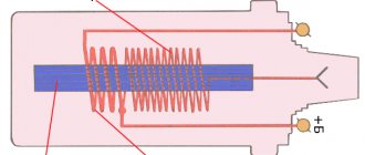
Ignition coil
The coil (bobbin) is a step-up two-winding transformer. It increases the voltage of the on-board network to several tens of thousands of volts.
With the help of an ignition coil, the voltage of the on-board network is increased to several tens of thousands of volts
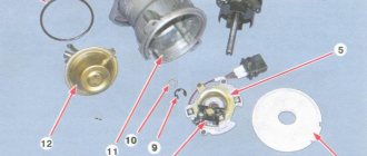
Distributor (distributor)
The distributor is used to distribute the pulse voltage coming from the high-voltage winding of the coil to the rotor of the device along the contacts of the top cover. This distribution is carried out by means of a slider having external contact and located on the rotor.
The distributor is designed to distribute voltage across the engine cylinders
Breaker
The breaker is part of the distributor and is designed to create electrical impulses in a low-voltage circuit. Its design is based on two contacts - stationary and movable. The latter is driven by a cam located on the distributor shaft.
The breaker design is based on moving and stationary contacts
chopper capacitor
The capacitor prevents the formation of a spark (arc) at the breaker contacts if they are in the open position. One of its outputs is connected to the moving contact, the other to the stationary one.
The capacitor prevents sparking between the open contacts of the breaker
High voltage wires
Using high-voltage wires, voltage is supplied from the terminals of the distributor cover to the spark plugs. All wires have the same design. Each of them consists of a conductive core, insulation and special caps that protect the contact connection.
High-voltage wires transmit voltage from the contacts of the distributor cap to the spark plugs
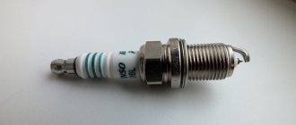
Spark plug
The VAZ 2106 engine has four cylinders, each of which has one spark plug. The main function of spark plugs is to create a powerful spark that can, at a certain moment, ignite the combustible mixture in the cylinder.
Spark plugs serve to ignite the fuel-air mixture
Operating principle of the ignition system
When you turn the ignition key, current begins to flow through the low-voltage circuit. It passes through the contacts of the breaker and enters the primary winding of the coil, where due to inductance its strength increases to a certain value. When the breaker contacts open, the current instantly drops to zero. As a result, an electromotive force arises in the high-voltage winding, increasing the voltage tens of thousands of times. At the moment such a pulse is given, the distributor rotor, moving in a circle, transmits voltage to one of the contacts of the distributor cover, from which voltage is supplied to the spark plug through a high-voltage wire.
This is interesting: Ignition switch device - operating principle
Operating principle of the device
So, after creating such an important device as a homemade car strobe light, you should understand the principle of its operation in order to seamlessly adjust the ignition angle in the future. A capacitor to which an electric current is applied is charged by a resistor. When the charge reaches the required level, the current is supplied by a resistor to the opened transistor. It is at this time that the relay begins to work, which is designed to create a circuit including a thyristor, diodes and a capacitor. The entire unit is a specialized divider through which the charge passes to the main contact of the thyristor. The opened control element entails the discharge of the capacitor, which is expressed through the lighting of the diodes. The flash of light that appears in the flashlight goes out. The main output of the transistor is connected through a thyristor and resistor to the central wire, as a result of which the transistor closes and the relay turns off.
The strobe for setting the ignition is signaled by a long glow of the diodes; this occurs due to a broken contact with a delay. After some time, the contact is de-energized and interrupted. The homemade device again assumes a state of inactivity, flashing at the moment the next impulse occurs. To achieve a brighter glow of the LEDs in the flashlight, you can use a capacitor with a larger capacity.
How to properly set up a homemade product
To test the device in practice and set the ignition timing, do the following:
Fines for crossing the stop line and speeding will no longer bother you!
- Warm up the engine and leave it idling.
- We connect a homemade strobe to a power source.
- We wind the copper sensor onto the core of the first cylinder.
- We direct the light source to a special mark that is applied to the body.
- Find a fixed point on the flywheel pulley.
- In order for the two points to come together, it is necessary to rotate the ignition housing and then fix it in a certain position.
In practice, homemade stroboscopes are in no way inferior to factory ones. The main thing is to correctly assemble the circuit and check the operation of the device. Home-made stroboscopes are quite inexpensive and can be easily repaired if necessary.
More details in my Logbook
After another tinkering with the car, the vehicle went astray. As always, I didn’t make a mark on the distributor - I forgot. There was clearly a lot of angle exposed to the ear, there was detonation. But by reducing the angle, I still didn’t achieve the former high-torque power. My friends didn't have a strobe light. I was puzzled by buying a new one, but after shopping, the desire disappeared; I had to pay 1000 wooden ones for a “flashlight”! The speculators have gone completely crazy! After searching for options to get out of this situation, I decided to do it myself! The only problem-free scheme with ease of installation and without various settings was a car strobe from a laser pointer by the author N. ZAETS “LED car strobe” (“Radio”, 2000, No. 9).
So it was recently redrawn for easier reading.
Looking for information about the performance of this circuit, I came across the EverGrand blog. It has a “signet” laid out in SL6, for mixing and subsequent etching on the board, with a very compact layout
THANK HIM SO MUCH! Very nice and helpful guy! I had a chance to talk to him due to the constant supply of voltage to the transistors (the strobe light was constantly on when connected to the battery). The reason was not in the circuit, but in non-working K561LE5 microcircuits. Whom the “narrow-eyed” rivet without checking! Only the third one earned! Purchased microcircuit!
What is required for assembly: 1. Microcircuit - K561LE5 (I took an analogue of HCF4001BE) Transistors: 2. KT315A - 1 pc. 3. KT815A - 1 pc.
Resistors: 4. 15k - 1 pc. 5. 3k - 1 pc. 6. 100k - 1 pc. 7. 4.7k - 1 pc. 8. 430 Ohm - 1 pc. (I set it to 100 Ohm, since the light was dim with the previous one) 9. 1k - 1 pc.
Capacitors: 10. 68 pF - 1 pc. 11. 3300 pF - 1 pc.
12. Antenna cable for TV. 13. Clothespin 14. LEDs in various designs.
Translated using LUT technology, then etched, drilled, soldered
Video “Visual instructions for self-installation of ultrasound using a strobe light”
You can learn how to correctly adjust the ignition angle of a car using a device such as a strobe from the video below (the author of the video is Vladislav Chikov).
The information is applicable to repairing many vehicles.
In general, it is believed that without a strobe and the basic mode it is definitely impossible to set up the OZ. But. Nothing is impossible on the territory of the former USSR.