Hi all! I think you have repeatedly seen cars with a certain structure on the hood designed to capture air and build up pressure, thereby increasing the power of the internal combustion engine. Here we are talking about a mechanical air blower for a car.
Today I want to talk about it in more detail. And you can decide for yourself whether it’s worth buying it, including second-hand on Avito, or trusting specialized specialists. Or maybe this is completely unnecessary for you, and it will just be interesting to understand the features and operating principle of the supercharger.
I would like to say right away that it is impossible to make such a thing for a car from a vacuum cleaner, even if it is a VAZ 2114. But you can install a supercharger on the carburetor and injector.
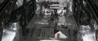
000_MOTO_1110_072
The advantages of centrifugals include simplicity of design, compactness and low weight.
There is also no strict need to use intercoolers, since they heat the air much less than vane superchargers and turbochargers. The advantages of centrifugals include simplicity of design, compactness and low weight. There is also no strict need to use intercoolers, since they heat the air much less than vane superchargers and turbochargers.
The idea of increasing engine power by pushing an additional portion of air and fuel into it is as old as the world. And this can be achieved if a pressure greater than atmospheric pressure is created at start-up. This is what superchargers are used for. There are many models, but in “Moto” Nos. 8 and 9 (Horex and me with my crazy “gold”) we talked about centrifugal ones. In short, these are high-speed fans, and, figuratively, “boy vacuum cleaners.”
The very idea of forced air injection into the cylinders was proposed shortly after the invention of the internal combustion engine itself. Already in 1885, Gottlieb Daimler received a German patent for the supercharger. The idea was that some external fan, pump or compressor would force an increased charge of air into the engine. In 1902, in France, Louis Renault patented a design for a centrifugal supercharger. But after the release of several cars, all work in this direction was stopped - the imperfection of technologies and materials tipped the scales with more “against” than “for”. The abbreviation PCN (driven centrifugal supercharger) took root in the everyday life of engine mechanics in the 30s of the twentieth century - however, only in aviation. The introduction of monitoring stations made it possible to kill two birds with one stone: to increase specific power and reduce the drop in power at high altitudes. (As altitude increases, the density of air decreases; accordingly, less of it enters the engine, and to maintain power, the oxidizer has to be forced in.) All superchargers installed on internal combustion engines can be divided into two main groups based on their operating principle: centrifugal and positive displacement. And according to the type of drive - drive (driven by the crankshaft) and gas turbine (using the energy of exhaust gases).
What is a monitoring station? Let's plunge into childhood and remember the spinning top. What happens if you splash water on top of a spinning top? That's right, water will splash around under the influence of inertial forces (centrifugal force), and the spinning top will remain almost dry. Likewise, in a centrifugal supercharger, the role of the spinning top is played by the impeller, and the role of water is played by air molecules. I think that as a child, everyone looked inside a vacuum cleaner and saw behind the grate of the dust collector compartment a strange disk with blades and a nut in the middle. This is the simplest centrifugal supercharger, only it works for suction, and not for creating excess pressure. What happens if you connect the hose to the vacuum cleaner, but from the side from which it blows air? And if it is also introduced into the engine intake...
The impeller of a real CN has a rather complex cone-shaped shape, and the blades have a complex profile and bend. The performance and efficiency of the entire supercharger depends on their geometry. (For example, the larger the diameter of the impeller, the more pressure it can produce at the same speed, but at the same time it consumes more power; or when the number of blades increases, the pressure increases, but the performance decreases.) The air, passing through the air channel into the supercharger, falls on the radial blades of the impeller. The blades throw it to the periphery of the casing through a thin slot. There, the air is slowed down in a snail-shaped diffuser, its speed drops, and the pressure rises.
In fact, the monitoring station is half of a turbocharger already familiar in the world, but instead of the “hot” (turbine) part, it is mechanically driven from the crankshaft. Due to the very principle of operation, the centrifugal supercharger has one significant drawback. To operate effectively, the impeller must rotate not just quickly, but very quickly. The pressure produced by a centrifugal compressor is proportional to the square of the impeller speed. Accordingly, hence the main disadvantage of centrifugals: a narrow operating range. But this theoretical minus in practice turns out to be a plus. After all, if the supercharger forcibly pumps air into the engine all the time, this will lead to an increase in traction throughout the entire speed range, and it will be difficult to cope with such “fruit” at the bottom. It’s another matter if excess pressure in the intake begins to arise at medium speeds and reaches a peak at high speeds, when the filling of the cylinders deteriorates due to friction losses on the intake tract of the air-fuel mixture (this causes the downward tail of the torque curve in the high speed range at many dino graphs). The centrifugal coolly “inflates” the tops, helping the mixture enter the cylinders in the required volume. That is why there is no need to turn off the supercharger at low speeds, as is necessary with positive displacement compressors.
Types of turbochargers
Turbine with exhaust gas bypass WGT.
The hot scroll of the turbocharger has a wastegate valve that releases exhaust gases bypassing the turbine rotor in order to limit the increase in turbocharger pressure above a predetermined value. As a result, the flow of gases through the turbine decreases, which reduces both the degree of air compression by the turbine and the excessively high rotation speed of the turbocharger shaft. At low engine loads, the valve closes and the entire exhaust gas flow is directed to the turbine.
Turbine with variable turbine geometry VNT.
A turbine with variable geometry TIG (Variable-Nozzle Turbine - VNT, Variable-Turbine Geometry - VTG, Variable-Geometry Turbo - VGT) differs from classic turbochargers by the presence of a ring of special blades (blades). This makes it possible to control the flow of exhaust gases through the turbine. At low engine speeds the blades are in a semi-closed state. Exhaust gases have to “squeeze” into the narrow passages between the blades. The speed of the gas increases (Bernoulli's law) and it spins the turbine faster. At higher engine speeds, the blades open. The cross section for the passage of gases increases, the speed drops, and the turbine rotates more slowly.
Turbine with VST throttling.
Spool-controlled turbines (VST Variable Sliding Turbine) have been used in low-power passenger car engines. The VST turbine operates similarly to a fixed geometry turbine, with the difference that one of the two spool ports is initially opened. When the maximum permissible boost pressure is reached, the spool, continuously moving in the axial direction, opens the second channel. The channels are designed so that the largest part of the exhaust gas flow is directed to the turbine. The remaining part of the exhaust gases, due to further movement of the control valve, is directed to bypass the compressor impeller inside the turbocharger.
Turbine with Twin-scroll (Twinscroll) - double snail. A “twin-scroll” turbine differs from a conventional one in the presence of two channels dividing the turbine’s working chamber in two. Thus, the exhaust gases are supplied to the turbine separately, due to which pulse charging is used more efficiently.
How is the advantage achieved? On a four-stroke engine, the cylinder operating order (for example, ZMZ-409) is 1-3-4-2. Let's imagine that cylinder 1 finishes its cycle and reaches the bottom point, the exhaust valve opens. At the same time, cylinder 2 completes the exhaust cycle by closing the exhaust valve and opening the intake valve. With a conventional single turbo, the exhaust pressure from cylinder 1 will prevent air intake from cylinder 2 since both exhaust valves are open. So, if you separate the cameras, the problem will be resolved. In addition, turbines with variable Twin-scroll have recently appeared: a distribution valve (Quick Spool Valve) is installed at the inlet of the turbine scroll, which redirects the flow of exhaust gases into different channels. And if we take into account that different channels have different geometries, then we actually get a universal, controllable turbine that works well at both low and high engine speeds.
Twin scroll turbocharger Borg Warner EFR-7163-J (VTV) with integrated QSV valve (variable geometry)
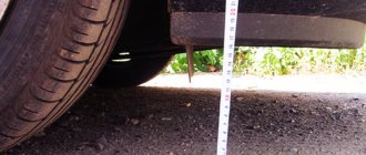
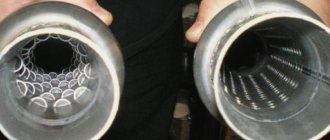
004_MOTO_1110_072
The size of the gap between the impeller blades and the housing is the main parameter affecting the efficiency of the compressor.
The size of the gap between the impeller blades and the housing is the main parameter affecting the efficiency of the compressor.
Everything is great, but centrifugal engines also have undeniable shortcomings. The main thing is that you need to spin the impeller to crazy speeds, so you have to use a step-up gearbox, which has 50–150 thousand rpm on the output shaft (for some monitoring stations this figure reaches 250 thousand!). Rare bearings and seals can withstand this, and therefore the issue of service life and efficiency is often more pressing than increasing power. And the overall efficiency of the engine is reduced due to the fact that the supercharger sucks power directly from the crankshaft. But every hole of problems can be climbed out of by a thin rope of technological solutions. For example, BRP on its sports jet skis drives the supercharger directly from the crankshaft flywheel gear, and is saved from gear-damaging jerks by using a friction damper on the supercharger shaft. Yamaha drives the snail through an intermediate shaft. If we look at the tuning units, we see that, for example, Rotrex (which is adored by European motorcycle tuners, including yours truly) uses a friction roller gearbox, in which the impeller shaft is sandwiched between the planetary gears and does not require bearings. The Americans from ProCharger, having brought a kit to the market for Harley-Davidson, focus on the precision of manufacturing the gearbox; their colleagues from Powerdyne like to “supercharge” snowmobiles and use an additional belt drive as a multiplier.
And again we remember our childhood, and also, who remembers, physics. When we inflated our bicycles, mopeds and motorcycles with pumps, remember how the hose going to the wheel got hot? That's right, more pressure means higher temperature, higher temperature means less air density, which means less oxygen molecules per unit volume. To compensate for this decrease in density, the compressed air must be cooled. How? The same as antifreeze or oil - in the radiator, or more precisely, in the intercooler (in scientific terms, charge air cooler). Intercoolers are mainly of the air-to-air type (a seemingly simple radiator with thicker channels) and air-to-liquid, when between the compressor and the intake manifold there is a compact “radiator in reverse”, which takes heat from the compressed air into the liquid, and then discharges it into atmosphere through an additional radiator.
But still, why not turbo? After all, in the world of cars, more and more manufacturers are equipping their cars with turbocharging. Alas, the “turbo” not only increases power, but also creates resistance at the exhaust, greatly heats the air at the intake not only due to its compression, but also due to the proximity of the hot exhaust manifold; in addition, the engine experiences “turbo lag” or “turbo lag” (when the impeller, having no mechanical connection with the crankshaft, does not have time to spin up after the throttle is opened, which causes a short-term dip in traction - the complete antithesis of the expression “follow the handle”). Because of all of the above, the turbo motorcycles that appeared in the early 80s (say, the Yamaha XJ650 Turbo) failed in the market, and now neither the designers of serial vehicles nor the tuners are in a hurry to “stick a snail” into motorcycle engines. The exception is drag racing equipment and other cars for record straight races; there, “turbo lag” is usually compensated by “anti-lag” (a system that allows you to sharply increase the temperature of the gases in front of the turbine - wild barbarity, justified only by complete disregard for the resource). However, let’s not say “never” - the French from Yam74, after experimenting with the Tmax monitoring station, eventually switched to the “turbo”, and not without success. Therefore, we will wait for developments.
TURBO NOT TURBO
If you examine the design of such units, you can identify a certain similarity in structure
Namely, such compressors operate from a drive that does not require intervention in the standard engine systems, namely the lubrication and exhaust gas system, which is very important! This design is really very simple - a direct connection is established with the “crankshaft”, which allows the engine and supercharger to interact perfectly during acceleration. That is, the higher the speed, the faster the “crankshaft” rotates, and accordingly the supercharger spins! Thanks to this interaction, there is practically no such thing as “turbo lag”
Also, an additional advantage is the lack of operation at high temperatures, like with TURBO options, which means that the service life is greatly increased - after all, here the “turbine” does not need to cool down, that is, “” or “boost controllers” are not required, we just turn off the car and work stops. The site autoflit.ru recommends doing exactly the same. If you're interested, come in.
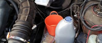
008_MOTO_1110_072
Rotrex disassembled (top) and its oil system (bottom).
The planetary gearbox with smooth rollers operates mainly due to a special oil circulating through the system. Therefore, unlike their gear counterparts, which are lubricated from the general engine lubrication system, Rotrex has its own oil circuit with a radiator and filter. Rotrex disassembled (top) and its oil system (bottom). The planetary gearbox with smooth rollers operates mainly due to a special oil circulating through the system. Therefore, unlike their gear counterparts, which are lubricated from the general engine lubrication system, Rotrex has its own oil circuit with a radiator and filter.
Design and operating principle of mechanical supercharging
In the modern automotive industry, several types of mechanical pressurization systems are used, each of which has its own design features and principle of air injection.
Mechanical pressurization device
The mechanical pressurization system consists of the following elements:
- mechanical supercharger (compressor);
- intercooler;
- throttle valve;
- bypass valve;
- air filter;
- boost pressure sensors;
- air temperature sensors in the intake manifold.
The mechanical supercharger is controlled using the throttle valve, which is open at high speeds. In this case, the pipeline damper is closed, and all air enters the engine intake manifold. When the engine is running at low speed, the throttle valve is opened at a slight angle and the piping damper is fully open, allowing some air to be returned to the compressor inlet.
The air coming from the supercharger passes through the intercooler, which reduces the temperature of the charge air by approximately 10°C, promoting a higher compression ratio.
Types of mechanical boost drive
The transmission of torque from the crankshaft to a mechanical compressor can be carried out in various ways:
- Direct drive system - involves mounting the compressor directly on the engine crankshaft flange.
- Belt drive. The transmission of force is realized using a belt. Different manufacturers use their own types of belts (flat, V-shaped or toothed). Belt systems have a short service life and are prone to slippage.
- Chain drive. It has a principle similar to a belt drive.
- Gear drive. The disadvantage of such a system is increased noise and large dimensions.
Types of mechanical compressors
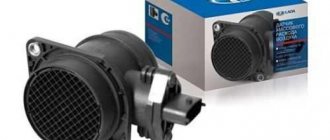
Each type of boost drive has its own operational characteristics. There are three types of mechanical superchargers:
- Centrifugal blower. The most common type of mechanical superchargers. The main working element of the system is the wheel (impeller), which has a similar design to the turbine compressor wheel. It rotates at a speed of about 60,000 revolutions per minute. In this case, air is sucked into the central part of the compressor wheel at high speed and low pressure. After passing through the supercharger blades, the air is supplied to the intake manifold, but at low speed and high pressure. This type of supercharger is used in conjunction with turbochargers to eliminate turbo lag.
- Screw blower. It is a system of two rotating augers (screws) of a conical shape. The air, entering the wider part, passes through the compressor chambers and, due to rotation, is compressed and forced into the intake manifold pipe. Such systems are used mainly on sports and expensive cars, since they are quite complex to manufacture. Their advantage is high operating efficiency.
- Cam blower (roots). One of the first types of mechanical superchargers. Structurally, it consists of two rotors with a complex cross-section profile. The rotor axes are connected by two identical gears. As the system rotates, air moves between the housing walls and the cams, resulting in its being forced into the intake manifold. The disadvantage of this system is the formation of excess pressure, which provokes malfunctions in the operation of the boost. To eliminate this phenomenon, the cam blower design includes either an electrically driven clutch (control with supercharger cut-off) or a bypass valve (without blower cut-off).
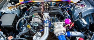
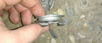
009_MOTO_1110_072
A homemade supercharger, built on the basis of a domestic turbocharger, in which the “hot” part was replaced by a gearbox.
The notch on the impeller is a consequence of balancing: the metal was cut not from the blade, but from where the notch would not create turbulence in the air flow. Our “Kulibins” used an “inside out” gearbox - it’s compact and the oil itself disperses along the teeth due to centrifugal force. The faceplate connects the snail and the gearbox. It also contains a bearing and an impeller shaft seal. A homemade supercharger, built on the basis of a domestic turbocharger, in which the “hot” part was replaced by a gearbox. The notch on the impeller is a consequence of balancing: the metal was cut not from the blade, but from where the notch would not create turbulence in the air flow. Our “Kulibins” used an “inside out” gearbox - it’s compact and the oil itself disperses along the teeth due to centrifugal force. The faceplate connects the snail and the gearbox. It also contains a bearing and an impeller shaft seal.
Driven blowers
How to install an air blower yourself
There are several approaches that allow you to install a mechanical air blower on VAZ family cars with your own hands. This means making a device yourself that provides turbo mode or boosting the engine, or using a ready-made KIT kit.
With this approach, the mechanical air blower will be decisive. The entire future design depends on it. The main thing is to find an air supercharger from an imported car that meets the requirements, or you will have to use a homemade one. This is also possible, and in this case suitable parts and components from completely unexpected devices, for example, a vacuum cleaner, are used.
Superchargers driven by gas wave pressure
A supercharger driven by wave pressure of gases (Fig. “Supercharger using wave pressure of gases”) is a gas-dynamic machine, the main component of which is a rotor with open channels located coaxially along its circumference (“sectional wheel” or “rotor”).
Through the openings for the inlet and outlet of fresh air and exhaust gases and the end surfaces of the rotor, the pressure in the channels is increased. Fresh air is compressed in the rotor channels during gas-dynamic processes. During this process, fresh gas and exhaust gases briefly come into contact with each other. Essential for operation is the physical fact that the process of gas-dynamic compression occurs over a significantly shorter period of time than the time of mixing of two gas flows.
The principle of operation of a supercharger driven by gas wave pressure is based on the fact that the pressure wave at the open end is reflected as a rarefaction wave, and at the closed end as a pressure wave; this also applies to the reflection of a rarefaction wave. To control and maintain this
process, the channel openings must pass through “open ends” and “closed ends”, i.e. the sectional rotor must rotate. The drive power is used simply to compensate for rotor bearing and ventilation losses and to accelerate the rotor in the event of a sudden increase in load. By appropriately configuring the housing gas path, it is possible to ensure a sufficiently uniform temperature distribution in the rotor to ensure sufficiently small clearances. Acoustic performance can be improved by configuring sections accordingly.
The gas flow and state diagrams (Figure "Gas Flow and State Diagram of a Wave Pressure Supercharger") illustrate the processes in a basic supercharger driven by gas pressure wave at wide open throttle and moderate engine speed. The energy exchange in the ducts occurs at the speed of sound, and thanks to the operating principles used, the supercharger reacts very quickly to changes in engine demand, with the actual reaction time being determined by the charging processes in the air ducts and exhaust pipes. The speed of sound, as well as the physical characteristics, are a function of temperature, which means they are primarily dependent on the amount of engine torque rather than the engine speed.
Comprex supercharger
If the transmission ratio between the engine and the sectional rotor is constant, as is the case for a belt-driven supercharger, the wave process is optimal only at a certain operating point. To eliminate this drawback, special “pockets” are placed in the front part of the casings, allowing for high supercharger performance and an optimal boost curve in a relatively wide range of operating conditions.
The Comprex blower rotor is permanently lubricated and the rotor bearing is located on the air inlet and outlet sides. The air casing is made of aluminum, and the gas casing is made of NiResist material. The rotor with axial cells is made by lost wax casting. The boost pressure is adjusted according to engine demand using a bypass valve.