03/04/2022 2,514 VAZ 2114
Author: Ivan Baranov
The mass air flow sensor is used to estimate and balance the air flow entering the engine. Signals from the device are sent to the motor control unit. Based on data from the mass air flow sensor and other sensors, the required mixture composition is formed. To prevent the device from breaking down on the road, it is necessary to diagnose it. There are several ways to check the mass air flow sensor on a VAZ 2114.
[Hide]
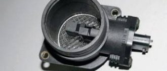
DMVR device on VAZ 2114
The overall design of the sensor consists of two filaments made of a platinum-based alloy. The threads are heated by electric current, with one being the working thread and the other being the control thread. The working element is located in the air flow supplied to the engine, which cools the part. As the temperature of the filament changes, resistance increases or decreases. The data is compared with the parameters of the control element, and based on this, the amount of air passed is automatically calculated.
On later VAZ 2114 models, thermistors began to be used, which have increased durability and measurement accuracy. This is exactly the sensor that is used on the VAZ 2114.
Where is the mass air flow sensor located?
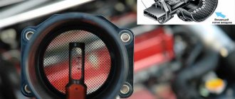
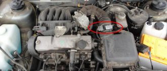
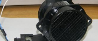
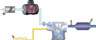
The mass air flow sensor on the VAZ 2114 is located in the air duct located behind the air purification filter. A wiring harness is connected to the sensor, ending with a plug.
Installation location of the air flow sensor on the VAZ 2114 engine
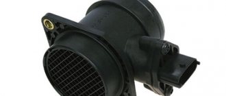
Sensor design features
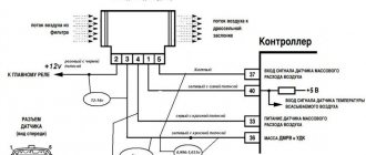
The VAZ 2114 can use mass air flow sensors of domestic and imported origin. The design of the devices is the same and corresponds to the diagram below.
Design of the air flow sensor VAZ 2114
The DMRV includes:
- 1 — block for connecting the wiring harness;
- 2 — sensor operation controller;
- 3 - measuring element;
- 4 — outer body;
- 5 — metal protective mesh;
- 6 — guide deflector;
- 7 — fastening the sensor body to the body;
- 8 — direction of air flow.
Types of mass air flow sensors, their design features and operating principle
Three types of VU meters are most widespread:
- Wire or thread.
- Film.
- Volumetric.
In the first two, the operating principle is based on obtaining information about the mass of the air flow by measuring its temperature. The latter may involve two accounting options:
- By changing the position of the slider, driven by a special blade, which is affected by the air flow passing through the device. Considering the presence of rubbing mechanisms, the level of reliability of such structures is quite low. This was the main reason for the refusal of car manufacturers from sensors of this type. For reference, here is a simplified example of the design of a volumetric flow meter.
Volumetric air flow sensor device - By counting Karman vortices. They are formed if a laminar air flow washes over an obstacle whose edges are quite sharp. The frequency of the vortices breaking off from them is directly related to the speed of air flow passing through the device.
Vortex sensor design (widely used by Mitsubishi Motors)
Designations:
- A – pressure measurement sensor to record the passage of the vortex. That is, the frequency of pressure and vortex formation will be the same, which makes it possible to measure the flow of the air mixture. At the output, using an ADC, the analog signal is converted to digital and transmitted to the ECU.
- B - special tubes that form an air flow similar in properties to laminar.
- C – bypass air ducts.
- D – column with sharp edges on which Karman vortices are formed.
- E – holes used to measure pressure.
- F – direction of air flow.
Wire sensors
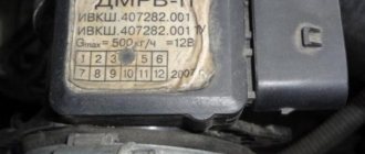
Until recently, thread mass air flow sensor was the most common type of sensor installed on domestic cars of the GAZ and VAZ model range. An example of a wire flow meter design is shown below.
Design of volumetric meter IVKSH 407282.000
Designations:
- A – Electronic board.
- B – Connector for connecting the mass air flow sensor to the computer.
- C – CO adjustment.
- D – Flow meter housing.
- E – Ring.
- F – Platinum wire.
- G – Resistor for temperature compensation.
- N – Ring holder.
- I – Electronic board casing.
Operating principle and example of a functional diagram of a filament VU meter.
Having understood the design of the device, let's move on to the principle of its operation, it is based on the hot-wire method, in which a thermistor (RT), heated by the current passing through it, is placed in the air flow. Under its influence, the heat transfer changes, and, accordingly, the resistance RT, which makes it possible to calculate the volumetric flow rate of the air mixture? using King's equation:
where I is the current passing through RT and heating it to temperature T1. In this case, T2 is the ambient temperature, and K1 and K2 are constant coefficients.
Based on the above formula, you can derive the volumetric air flow rate:
An example of a functional diagram with bridge connection of thermoelements is shown below.
Typical functional diagram of a wire mass air flow sensor
Designations:
- Q - measured air flow.
- U – signal amplifier.
- RT - thermal resistance wire, usually made of platinum or tungsten filament, the thickness of which is in the range of 5.0-20.0 microns.
- RR – temperature compensator.
- R1-R3 are ordinary resistances.
When the flow velocity is close to zero, the RT is heated to a certain temperature by the current passing through it, which allows the bridge to be kept in equilibrium. As soon as the flow of the air mixture increases, the thermistor begins to cool, which leads to a change in its internal resistance, and, as a result, an imbalance in the bridge circuit. As a result of this process, a current is generated at the output of the amplifier unit, which partially passes through the temperature compensator, which leads to the release of heat and makes it possible to compensate for its loss from the flow of the air mixture and restores the balance of the bridge.
The described process allows you to calculate the flow rate of the air mixture based on the amount of current passing through the bridge. In order for the signal to be perceived by the ECU, it is converted into a digital or analog format. The first allows you to determine the flow rate by the frequency of the output voltage, the second - by its level.
This implementation has a significant drawback - a high temperature error, so many manufacturers add a thermistor similar to the main one to the design, but do not expose it to air flow.
During operation, dust or dirt deposits may accumulate on the wire thermistor; to prevent this, this element is subjected to short-term high-temperature heating. It is performed after the internal combustion engine is turned off.
Film air meters
A film MAF works on the same principle as a filament one. The main differences lie in the design. In particular, silicon crystal is used instead of platinum filament resistance wire. It is coated with several layers of platinum plating, each of which plays a specific functional role, namely:
- Temperature sensor.
- Thermal resistances (usually there are two of them).
- Heating (compensation) resistor.
What is the optimal air flow for VAZ 2114 cars?
The amount of air required to form the mixture depends on the speed:
- at idle speed (850-950 rpm) - 9.5-10.5 kg of air per hour;
- at medium speed (2000 rpm) - 19-21 kg of air per hour.
Reducing the air supply leads to a leaner mixture, and increasing it leads to a richer mixture. Small deviations in measurement accuracy have little effect on the operation of the engine, but with errors of 2-3 kg, the engine begins to operate unstably. Some control units compensate for measurement inaccuracies based on data from other sensors. For example, the January 5.1 block additionally adjusts the mixture composition based on the signal from the lambda probe.
The main causes of failure of the mass air flow sensor
The most common causes of sensor failure are:
- dust ingress;
- oil contamination;
- short circuit of the wiring due to damage to the insulation or plug;
- mechanical damage to active elements.
A common cause of incorrect operation of the mass air flow sensor is the failure of electronic components, which increases the sensor’s response time to changes in air flow. A working sensor monitors changes at a speed of 0.5 ms, and if it breaks down, the response time increases by 20-30 times. The defect is detected only by recording the operation graph with an oscilloscope. Such a sensor cannot be repaired; it must be replaced with a new one.
What factors disable the mass air flow sensor?
Factors causing failure of the air flow sensor:
- Dust may be caused by improper installation of the sensor on the filter, which causes the sealing ring to become distorted. With this defect, a thin coating of contamination will be present on the sensor input grid. Another cause of dust is a clogged air filter, so regular maintenance will prolong the life of the air flow sensor.
- Oil is thrown onto the sensor if the level in the crankcase is high or if the oil separator in the ventilation system is clogged. An additional negative factor is engine wear, which causes lubricant to actively enter the crankcase ventilation.
- Contact with sharp objects on the insulation, oiling. Such impacts are the result of careless repairs.
- Damage to the sensor is possible during vehicle maintenance (impacts to the body) or during improper cleaning of the active part.
Characteristic signs of failure of the mass air flow sensor
Symptoms of DMRV malfunctions:
- Unstable engine operation at idle;
- reduction in acceleration dynamics;
- spontaneous change in speed in all operating modes;
- difficulty starting;
- Check Engine light turns on.
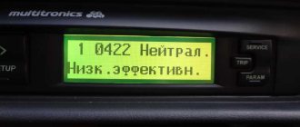
If an additional trip computer is installed on a VAZ 2114 car, then during diagnostics, in addition to direct sensor errors, codes indicating misfires and lean mixture conditions are possible.
What's the result?
As you can see, if there are signs of problems and the first symptoms of the DMVR VAZ 2114 or another car appear, you should check the device as soon as possible for possible breakdown. In this case, you can quickly diagnose the air flow sensor with a multimeter in a regular garage.
For this reason, it is necessary to perform regular checks of the ECM, scan for errors, and also pay attention to any failures and symptoms of malfunctions of the sensors of the electronic engine control system (TSP, DPKV, etc.).
How to check the mass air flow sensor yourself?
To independently check the sensor, there are several methods based on disconnection, as well as inspection and testing with a multimeter. There are no other diagnostic methods at home. A thorough inspection of the mass air flow sensor is carried out on a special stand, which makes it possible to record sensor problems under various operating modes. Another common testing method is to install an identical device removed from another vehicle.
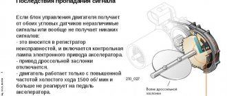
Disabling the mass air flow sensor
The easiest way to check the mass air flow sensor on a VAZ 2114 is to disconnect the plug. If there is no signal, the engine control unit goes into emergency operation mode, determining the approximate air volume based on the throttle position. At the same time, fuel consumption increases slightly - for the VAZ 2114 it reaches 10-12 liters per 100 km. A characteristic feature is the increase in idle speed to 1500 rpm. But when using the controller January 7.2. or Bosch M7.9.7 the increase in idle speed is not carried out due to the features of the software.
Visual inspection
External inspection requires removal of the air duct from the sensor. During the inspection, the dustiness of the inside of the housing and the corrugated air supply hose is assessed. There should be no traces of oil or dust on the surface.
Checking the device with a multimeter
The purpose of diagnostics is to measure the voltage supplied by the sensor.
Bosch products are checked in a similar way:
- 0280218004;
- 0280218037;
- 0280218116.
To measure you will need:
- test device:
- a set of measuring probes;
- WD-40 liquid.
The measurement is made between the yellow and green wires. Voltage values can be displayed on the screen of some on-board computers (menu voltage from sensors, U Mass air flow sensor).
Checking the mass air flow sensor using a multimeter is demonstrated in the video from “IZO))) LENTA”.
Determining the pinout of the mass air flow sensor
The location of the wires in the block starting from those closest to the windshield:
- yellow - positive input signal (in diagram 7);
- gray-white insulator - positive power signal (in diagram 12);
- green — sensor grounding (in diagram 30);
- pink-black insulator - sending a signal to the main relay.
Pinout of MAF contacts
Other colors of wiring insulation are possible, but the pinout sequence remains unchanged.
Instructions for testing
Measurement sequence:
- Insert the probes into the connector to the places where the wires are installed. To facilitate the procedure, the probes are lubricated with WD-40 liquid. The positive signal comes from the yellow wire, the negative signal from the green wire. It is not recommended to pierce the insulation and use additional cables, as this reduces the accuracy of the measurement.
- Switch the multimeter to DC voltage measurement mode with a limit value of 2.0 volts.
- Turn on the ignition, do not start the engine.
- Measure the voltage and compare it with the required value.
Comparison of test results with established standards
In accordance with the table, the sensor state is determined based on the measurement results.
| Voltage, V | Sensor status |
| 0,996-1,01 | New sensor |
| 1,01-1,02 | Working condition |
| 1,02-1,03 | Beginning of sensor wear |
| 1,03-1,04 | It is advisable to replace |
| More than 1.04 | Sensor is faulty |
Functionality check
Before diagnosing the mass air flow sensor, you need to know the symptoms that allow you to determine the degree of performance of the MAF (abbreviation for the English name of the device) sensor in the car. We list the main symptoms of a malfunction:
- The consumption of the fuel mixture has increased significantly, while at the same time acceleration has slowed down.
- The internal combustion engine idles with jerks. In this case, a decrease or increase in speed may be observed in idle mode.
- The engine does not start. Actually, this reason in itself does not mean that the flow meter in the car is faulty; there may be other reasons.
- A message appears about a problem with the engine (Cheeck Engine)
Example of the "Cheeck Engine" message displayed (marked in green)
These signs indicate a possible malfunction of the mass air flow sensor; in order to accurately determine the cause of the failure, diagnostics must be performed. It's easy to do it yourself. Connecting a diagnostic adapter to the ECU (if this option is possible) will help to significantly simplify the task, and then determine the serviceability or malfunction of the sensor using the error code. For example, error p0100 indicates a fault in the flow meter circuit.
Finding an error using a diagnostic adapter
But if you need to carry out diagnostics on domestic cars manufactured 10 years ago or more, then checking the mass air flow sensor can be carried out in one of the following ways:
- Testing while moving.
- Diagnostics using a multimeter or tester.
- External inspection of the sensor.
- Installation of a similar, known-good device.
How to restore the mass air flow sensor?
The optimal solution for problems with the mass air flow sensor is to replace the faulty sensor with a new one. But since the cost of the device is about 2500-3900 rubles, many owners are trying to “revive” the old part.
There are four recovery methods:
- installation of additional resistance;
- blocking part of the air supply channel to the thermistor with aluminum tape;
- updating the engine control unit firmware;
- washing the sensor body and housing from dirt.
Installing additional resistance
Additional resistances are installed in the circuit connecting the sensor to the control unit. When an electric current passes, the voltage decreases, which can be brought to the required limits. The resistance value is selected experimentally. Most often, a 1 kOhm resistor is soldered to the yellow wire and a 15 kOhm element to the green wire.
Blocking part of the air supply channel
The repair principle is based on partially cutting off the air supply to the thermistor. Due to this, less intensive cooling is ensured and it is possible to bring the voltage value to the state of a working device. The cross section is selected experimentally with voltage monitoring using a multimeter. In some cases, owners block the supply channel by 70-80%. Aluminum tape is used for gluing.
Sealing the canal with tape
The photo clearly shows the area of the closed channel
Correcting the firmware of the engine control unit
An adjustment means a change in the calibration or operating schedule of the mass air flow sensor stored in the unit’s memory. The dependence graph is constructed in such a way that at a sensor voltage of 0.996 volts, the flow rate is considered equal to zero. But if the sensor fails and the starting voltage is 1.055 volts, then the control unit considers the air supply to be 1.8 kg when the engine is not running. Changing the graph using the MAF Corrector utility will allow you to set the flow rate to 0, which will improve engine performance. This method can be recommended to owners who are well versed in the control unit software.
Do-it-yourself cleaning of the air flow sensor
The air volume sensor is cleaned after it is detected that it is not working correctly. The procedure is performed by partially disassembling and removing the device body with active elements. At the same time, the body is washed and cleaned from remaining leaves and dirt deposits. In many cases, washing the air flow sensor on a VAZ 2114 does not help restore the device’s parameters.
Mechanical methods of cleaning the mass air flow sensor on the VAZ 2114 are prohibited, as is blowing dust with compressed air.
What products should be used to clean the sensor?
To clean sensors, there are special liquids supplied in pressurized aerosol cans. An example of such a product is a special air flow sensor cleaner Luftmassensor-Reiniger from Liqui Moly. There are similar liquids from other manufacturers. You can wash the sensor with a mixture of 70% isopropyl alcohol and 30% distilled water, after warming the device to 60-70 ºС with a hair dryer.
When washing the mass flow sensor it is prohibited:
- try to clean the sensor with cotton balls, hard objects and brushes;
- use household cleaning products;
- Use carburetor cleaners based on acetone or ether.
Cleaners based on heavy petroleum products, for example, WD40, will remove plaque from working parts, but will leave a greasy film that must be washed off with isopropyl alcohol. The use of ether-containing substances is not recommended due to the destruction of the compound filling and electronic components.
Algorithm of actions
Sequence of steps when washing the mass air flow sensor:
- Remove the sensor together with the housing from the engine air duct. The device is attached with a clamp to the channel and two bolts to the air filter housing.
- Unscrew the two screws securing the sensor to the housing. The bolts have a star head, but many owners unscrew them with pliers.
- Wash the measuring thermistors and the air passage channels with a cleaning agent. If the cleaning method with alcohol is used, the removed sensor is heated with a stream of warm air and placed in a container. The alcohol-water mixture is also heated to 60-70 degrees.
- Dry the sensor.
- Wash the sensor housing with warm soapy water. Rinse under running water and dry.
- Assemble the sensor and install it in place.
Photo gallery
The photographs show some of the steps for flushing the air flow sensor of a VAZ 2114.
Unscrewing screws with pliers
Disassembled mass air flow sensor
Work Item Appearance
Sensor from a different angle
The second element is clearly visible in the channel
First flush point
Second flush point
Third flush point
The inside of the washed body
General view of the case