The tachometer is a device that is actively used on gasoline and diesel cars. This device is used to measure the rotation speed (rpm) of the crankshaft or generator. Most modern vehicles are equipped with a standard tachometer straight from the factory.
The need to independently install a tachometer on a diesel engine may arise for various reasons. It should be noted that the tachometer connection diagram on a diesel engine is somewhat different from a similar solution for gasoline internal combustion engines. When choosing a tachometer for a diesel engine, it is necessary to take this feature into account, since a tachometer for gasoline engines will not fit on a diesel engine.
We also recommend reading the article on how to replace the glow plugs of a diesel engine yourself. From this article you will learn about the features of the procedure for replacing glow plugs.
How to connect a car tachometer with your own hands
The main function of the tachometer in a car is to determine the correct gear, which has a positive effect on the life of the engine. Most cars have an analog tachometer built into them during assembly.
The driver looks at the arrow approaching the red line and knows when to shift into a higher gear.
Not all cars have the type of device that satisfies the owner, so you just need to figure out what they have and how to connect the tachometer.
Did you know? The term “tachometer” comes from the Greek τάχος - speed and μέτρον - measure.
Types of tachometers
There are two types of tachometers: digital and analog.
The first looks like a small screen on which the driver can see all the data he needs while driving.
The second one is simpler and looks like a board with arrows and values.
Remote
A remote tachometer is installed on the front panel of the car. For greater ease of placement, this device has a leg for mounting on the panel.
In addition, their stylish appearance gives the car elegance.
Staff
The standard tachometer is built into the dashboard of the car. This device is more convenient, since it is easier for the driver to perceive the movement of one arrow, rather than several indicators while driving. A standard tachometer is more often used in cars, and manufacturers of electronic devices produce kits for self-equipping cars.
Important! Measuring instruments are produced according to the car brand. The readings from a non-native mechanism will be incorrect. https://www.youtube.com/embed/TdI-Nn8XjmY
How to connect a tachometer through the computer If your car does not have a carburetor engine, and the injector, the tachometer is not connected to the ignition. In this case, you need to connect the engine control unit to the controller.
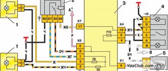
The connection diagram for the tachometer is simple: take the ground to the body (ground), connect the plus from the device to the ignition positive. The tachometer has two inputs: the first goes to the control unit, the second to the crankshaft position sensor.
The device connected to the computer will read pulses directly from the control unit controller.
Connection diagram for a tachometer on a gasoline engine
Secure the mechanism in its place (the location is determined by the type of device). Connect the black wire to the ground (body) of the car. Connect the red wire to the ignition switch terminal, which supplies 12 W during operation of the ignition system.
The third wire can be any color. Since the ignition system is contact and non-contact, we will consider where to connect the tachometer in both. With a contact system, the device is connected to the distributor breaker. In the second system - to the voltage switch.
If the car has a display backlight, the tachometer is connected to the terminal provided for this in the ignition switch.
How to connect a tachometer to a diesel engine
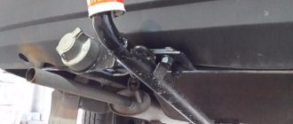
Since the process is labor-intensive, it must be carried out in an inspection pit. The first point of work is to dismantle the protective casing of the generator, try to avoid getting dirt. The second step is connecting the tachometer to the diesel generator. To do this, find the terminal marked “W” on the generator body and connect the device output to it.
Attention! It is imperative to close the contact coming from the oil pump. If this is not done, the tachometer may “lie”. It happens that it is impossible to find the terminal indicated above.
In this case, disassemble the generator. Connect one of the wires connecting the winding and the rectifier to the tachometer cable. Insulate the wires and reassemble the generator in reverse order.
It happens that the terminal indicated above cannot be found. In this case, disassemble the generator. Connect one of the wires connecting the winding and the rectifier to the tachometer cable. Insulate the wires and reassemble the generator in reverse order.
How to check the tachometer for functionality
We figured out how to connect a tachometer to a diesel and carburetor engine. Now let's look at the reasons for device breakdowns.
You notice problems in the operation of the measuring device, for example, an arrow jumping in different directions. There may be several reasons for the breakdown. If the engine runs for a long time, vibration will occur, which may damage the display.
The next reason may be oxidation of the contact group of the electrical wiring, damage to its insulation or disconnection from the tips. These are all visible causes that need to be eliminated immediately. If the sensor itself is broken, it needs replacement.
Interesting! The tachometer was designed by the American Curtis Widder in 1903.
Ignition system for gasoline engines
Control of engine ignition processes can be organized by several methods:
- Distributor with one ignition coil;
- Distributorless with a dual (triple, quadruple depending on the number of cylinders divided by 2) ignition coil;
- Individual (for each spark plug).
In all cases, the coil receives a powerful pulse with an amplitude of 12V from a breaker (for cars before the 90s), a transistor switch, or directly from the engine control unit. It is from this point that the signal to the tachometer should be taken.
We recommend: How to assemble a subwoofer box yourself
Installation of the device
Installation of the sensor is carried out according to the operating instructions. In order to connect a tachometer to a boat, first determine the location where the device will be mounted. The device must not be blocked by the steering wheel.
The proprietary connecting wire is attached to the connector. It has the required length and tips, the color scheme corresponds to the connection diagram described in the instructions. If there is no harness, they independently calculate the footage from the engine to the installation site of the watercraft and make it. When installing the sensor in the dashboard, a hole with a diameter of 86 mm is cut out and attached to the prepared place.
When installing a tachometer on a boat engine with its own power supply, several turns of the connecting cable are made around the spark plug wire. The number of turns and the distance to the NW are specified in the user manual. Most often, the manufacturer offers 3-6 turns at a distance of 4 cm from the NW. Then the power cable is connected to the terminals and secured with insulating tape or soldered, the soldering area is covered with heat-shrinkable material. The wire should not touch the moving mechanisms of the motor. If there is no IP, the harness is attached to the magneto coils.
Digital index
It's no secret that even expensive cars still use an analog tachometer, which is considered the most comfortable for the eye and the most common for quick reading.
How is this convenient? Firstly, this way you can catch a more suitable moment to change gears. Secondly, such a device is often used by fuel system tuners to achieve optimal engine operating conditions and mixture quality.
Obviously, such technology is more complex, and therefore its use on modern automotive technology is still very limited. The electronic device is based on a liquid crystal display, which is either included in the main analog tachometer or has its own place on the dashboard.
In addition to the display, there is a so-called analog-to-digital converter, which converts pulses from a magnetic coil into a digital signal in binary format. Typically this signal is sent to a digital processor. Its task is to analyze the received data and send it to the display in a form that will be understandable to the end user, the driver. Communication between the devices is carried out by an optocoupler, whose task is to diagnose the idle air valve to compare the received data with the reference data and adjust the output values.
Do-it-yourself tachometer installation: accessible instructions
A car enthusiast who cares about his car should have, among other devices, a tachometer, which helps to operate the car correctly. If there is no standard device, then it should be installed. The article describes their types and gives instructions on how to correctly connect the tachometer to a diesel engine and to a gasoline engine.
The tachometer informs you about the number of crankshaft revolutions, which helps you determine at what point it is best to change gears. This makes it possible to increase the service life of the power unit and operate it competently, since the power and traction characteristics of the engine depend on the crankshaft speed. In addition, it can be used to accurately adjust the carburetor and other important idle speed components.
This meter can be analog, which is a display with arrows and numbers. When the needle approaches the red line, the driver must shift to a higher gear. On the digital device, information for the driver is displayed on a small screen (video author – Armadil).
Conventionally, devices can be divided into two types:
- Regular ones. They are installed at the factory that manufactures the vehicle. They place it on the torpedo.
- Remote. They are an alternative option if a factory device is not available. Remote devices have more accurate readings, so they can be used to check the accuracy of standard readings. Sometimes they are installed as tuning.
The tachometer can be installed on both a gasoline engine and a diesel unit.
Connection to a gasoline engine
The connection of the device is different on an injection engine and with a carburetor. With the injector it is connected to the ECU controller. In this case, the “ground” is diverted to the body, and the positive wire must be connected to the positive ignition terminal.
The device has two outputs: one goes to the crankshaft position sensor, and the other goes to the ECU. Thus, it will read the number of revolutions from the controller of the control unit. Below is a diagram of connecting a tachometer with BSZ.
Below are instructions on how to connect an electronic tachometer to a gasoline power unit:
- First, depending on the type of device, you need to install it at the place where it will be located.
- Next, the installed tachometer should be connected. The negative wire is usually black and connected to ground.
- The red wire should be connected to the positive of the ignition switch, which is supplied with 12 V when the ignition system (SZ) is operating.
- The third wire can have any color - this is the input of the device. It is connected depending on the SZ. If the SZ is contact, then the device is connected to the distributor breaker; in the case of a non-contact SZ, it must be connected to a voltage switch.
- If the car is equipped with a backlight, the device must be connected to the car's size switch.
Connecting the device to a diesel engine
Diesel owners should know how to install a tachometer on a diesel engine, since its connection has nuances. To do this, you need to understand the principle of its operation. In the case of a gasoline power unit, it reads the pulses arriving at the ignition coil, and in the case of a diesel engine, from the “W” terminal of the generator.
It is better to install the device on a diesel engine by placing the car on an inspection hole or a lift. Connecting the electronic tachometer is carried out in stages. The first step is to remove the protective cover, avoiding contamination.
Next, on the generator you should find the terminal marked with the letter “W” and connect the wire from the tachometer to it. If you cannot find the terminal, you will have to disassemble the generator.
After disassembly, you need to connect one of the three wires that go from the winding to the built-in rectifier with a wire prepared in advance. The connection point must be insulated and the wire brought out. Next, the generator should be assembled in reverse order. The output wire from the generator must be connected to the meter.
For accurate readings, it is necessary to close the contact that comes from the oil pump.
Checking the tachometer functionality
Everything is clear with the installation of the tachometer, thanks to the instructions outlined above. It remains to find out the reasons for the meter malfunctions. Sometimes drivers can observe a situation when the arrow begins to twitch from side to side.
There are several possible reasons for the malfunction:
- When the motor operates for a long time, the resulting vibrations can damage the device;
- faults associated with wiring: tips may become detached, contacts may oxidize, and insulation may be damaged.
These damages can be identified by visual inspection and repaired. If the sensor is faulty, it must be replaced.
Technical solution
Before connecting the tachometer, it is necessary to draw up an electrical connection diagram in order to mentally determine the starting and ending switching points and trace the conductor. Any ignition coil has a terminal (terminal) +15 (ignition on), to which battery voltage is supplied when the key is turned to the first (for some cars, second) position. Under no circumstances should you connect the tachometer to this point; the first time you turn it on, it may fail. High-voltage wires also pose a danger, even to humans. The signal input to which the tachometer should be connected must be precisely determined. In older coils it is designated by the letter "K", it is better to find the exact circuit diagram of the car.
The next, more difficult task is the electrical connection of the nodes. As a conductor, you should take a stranded copper wire with a cross-section of at least 2 sq. mm. with polyvinyl chloride insulation.
The connection points of the wire to the ignition coil are cleaned, mechanically twisted, soldered and carefully insulated. Lay the wire along any electrical harnesses, using plastic clamps, towards the engine compartment bulkhead near the dashboard. You can insert the conductor into the passenger compartment next to any electrical wiring harness. To do this, it is easier to use an elastic string. Finally, connect the conductor to the tachometer signal terminal. In some cars that include modifications with or without a tachometer, you can simply change the dashboard, find the stock wire and connect it to the ignition coil.
Chinese models
Adjusting the carburetor of a Chinese chainsaw, for example, Carver, is carried out in almost the same way as factory models. There are the same three main adjustment screws L, N, T. Sometimes such models have the ability to adjust the idle speed. But as a rule, employees of specialized services and owners of such saws claim that it is not always possible to set up a high-quality Chinese chainsaw right away.
For classic Chinese models, screw L should be loosened 1.5 turns from the maximum value. Screw H must be loosened one revolution from the maximum. Idle speed is adjusted in the same way.
The popularity of hand chainsaws is quite high, so they are used not only for work in the forest, but also in the household, for example, for pruning trees
They have many advantages, among which it is important to highlight mobility, reliability, and long service life. Although the last point depends not only on the quality of the tool, but also on the nature of its operation
The nature of operation includes not only compliance with the correct sawing technology, but also ensuring the care of the tool. In particular, starting to use a new chainsaw requires a break-in, after which you may need to adjust the carburetor. For such purposes, you will need a tachometer for a chainsaw.
Microelectric Voltage Generated Machine
The tachometer generator converts the shaft rotation indicator into an electrical signal. Its operation uses the properties of the angular velocity of the rotor, the excitation flow, which is proportional to the generated EMF. Most modern tachogenerators are the permanent magnet type. These devices use a rotating joint, one end of which is connected to the machine shaft, inducing an electromotive force (voltage) proportional to the speed of the shaft. The armature contacts are connected to the voltmeter circuit, converting the voltage into a speed value.
Tachometer for motorcycles
How to install an electronic tachometer on a motorcycle? Here, motor vehicle owners have a choice: either purchase ready-made equipment or make it themselves. Let's assume that there is a motorcycle, there is a device for monitoring revolutions. But how to connect an electronic tachometer? For these purposes, the TX-193 device from the six is best suited for installation on domestic brands of motorcycles.
The device has extraordinary accuracy, low weight, economical power consumption, and stable operation under vibration conditions. It must be said that this model cannot even be compared with any tachometers for motorcycles. The process of connecting the device to two-cylinder motorcycles with a starter and battery, as well as single-channel ignition, is no different from the process of connecting the same device to a VAZ. The input of the device is connected to the output of the primary winding of the ignition coil. The device can be powered from a battery. For this purpose, the unit has corresponding wires. Then it is recommended to build a switch into the positive cable. This is useful when the equipment is standing still. This way you can save battery power.
If the motorcycle is not domestic and there is still the same electronic tachometer, the connection diagram will change slightly. In this case, power will have to be supplied through the ignition switch. There are special contacts there for these purposes. If the motorcycle does not have a starter, then the battery should be connected to the output of the rectifier. And from the battery you can supply power directly to the tachometer through a switch. If you don't have a rectifier, you need to buy one. If you don't have a battery, you can install one. The simplest option is a power source from a UPS or an old flashlight. If you connect the measuring device directly to the generator coil, then it will burn out. To avoid this, you can ask your neighbor, a radio amateur, to make a voltage regulator using thyristors.
If the engine has three cylinders, then signals from two coils are input here. There are also technical possibilities for installing a tachometer on six-cylinder motorcycles, but for this you already need to purchase branded equipment.
Simple speed metronome
Tachometer comes from two Greek words: “tacho” meaning “speed” and “metronome” meaning “to measure”. It works on the principle of a generator and determines the voltage corresponding to the speed of the shaft. It is also known as a revolution counter. Principle of operation:
- induction;
- electromagnetic;
- electronic;
- optic.
Historically, the first mechanical tachometer was developed based on the measurement of centrifugal force. In 1817 they were used to measure the speed of traction machines, but after 1840 they were used primarily to measure the speed of vehicles. A digital tachometer is an optical sensor designed to determine the angular velocity of a rotating element. Areas of use:
- Cars, planes, tractors, trains, light rail vehicles and their repair.
- Laser tools.
- Medical use. A hematachometer is a device placed in an artery or vein that measures the speed of blood movement through a rotating turbine. The indications are used to diagnose circulatory problems such as thrombophlebitis.
- Analog audio recording that measures the speed of an audio tape.
- Estimation of traffic speed and volume.
Connecting the device yourself
Not everyone understands electronics, but it is still desirable to be able to connect a measuring device. This will not cause any difficulties, because there are only three wires. The first thing to do is take the wire from the tachometer into the engine compartment. The easiest way to do this is through the hole in the speedometer cable. Next you will need a piece of wire. It should be about one meter long, thin and tough. At one end, use electrical tape to secure the wire from the device. Try to work carefully. Carefully insert the other end of the wire into the holes in the cable and push. Connecting an electronic tachometer can be done as follows. The positive wire is connected to the ignition coil (pin B). Connect the signal wire to contact K of the same coil. Connect the minus to ground. Work as carefully as possible, the wires are very thin and very unreliable.
A device for measuring engine speed.
Tachometer
Recently, the problem of controlling car engine speed has become very relevant. Previously proposed schemes have a number of disadvantages associated with a large number of elements, high current consumption and the ability to control engine speed only in digital form.
Tachometer-2 or DIY Tachometer
You can assemble the tachometer offered below with your own hands; the device is very simple in design, but has good technical characteristics, and is assembled using available components. A tachometer can be very useful when adjusting operations with electronic ignition units of a car engine, when accurately setting economizer response thresholds, etc.
Tachometer-3
I offer a simple but reliable electronic tachometer that works on my Ford Escort. The device has a two-digit digital indicator showing the number of thousands and hundreds of revolutions per minute. The tachometer is powered from the vehicle's on-board network and consumes a current of 0.45A.
Electronic tachometer for car
The driver is sometimes interested in knowing how many revolutions the car engine develops. This can be determined using a simple electronic tachometer (Fig. 1), a measuring device whose scale is graduated in engine speed. It is conveniently located near the steering wheel.
Electronic tachometer for motorcycle
Many motorcycles, mopeds, scooters and other motorcycle equipment do not have such an important device as a tachometer. I offer a simple and reliable electronic tachometer. It is designed to work with a single-cylinder two-stroke internal combustion engine with a contact or contactless ignition system and can measure crankshaft speed up to 10,000 rpm.
Tachometer on Arduino
A tachometer is a useful tool for counting the RPM (revolutions per minute) of a wheel or anything that spins. The easiest way to make a tachometer is to use an IR transmitter and receiver. In this article, we will look at how to use an IR transmitter and receiver to make a tachometer using Arduino. The result is displayed on a 16x2 LCD display.
Simple tachometer with large numbers on ATmega8 and LCD 16×2
I propose a version of a tachometer on an AVR microcontroller with large numbers on a character display. The numbers are arranged from separate segments over the entire height of the display, which makes the device readings more readable. Designed for a measurement range from 300 to 9999 rpm. But it turned out that at higher (from 10,000) rpm, the least significant digit moves off the screen and the device displays the number of revolutions per minute divided by 10.
Let's start with definitions. What is a tachometer in a car? This is a device that records the crankshaft speed in a car.
Of course, its use is not limited to vehicles. Determining the number of revolutions per minute is necessary when working with various mechanisms:
- airplane turbine
- ship propulsion shaft
- power station generators
- high precision milling and lathes
- drilling rigs
- electricity and water metering devices.
In addition, instruments for measuring rotation speed are used in research work. Any tachometer consists of two parts:
- The rotation sensor takes readings from the shaft - the object of measurement
- The signaling device either sends a command to the control circuit of the mechanism, or simply displays data on a pointer device (digital display).
About company
Unfortunately, many domestic and imported cars lack one very important device - a tachometer. Based on the diagram published in. The device has a two-digit digital indicator showing the number of thousands and hundreds of revolutions per minute. The electronic tachometer is powered from the vehicle's on-board network and consumes a current of 0.45A. The electrical circuit diagram of the device is shown in the figure.
The operation of the control unit is described in detail in. The input driver and counter are assembled according to a standard circuit and have no special features, so they immediately begin to work. An intermediate memory on triggers has been introduced into the digital tachometer circuit to eliminate flickering of the indicator numbers during counting. The operating cycle time is set by selecting resistor R11, and the measurement time by selecting resistor R7. For a conventional four-stroke, four-cylinder automobile engine, an inductive sensor is used.
It consists of 50...70 turns of PEL 1 wire. One end of the sensor coil must be insulated, and the other must be connected to the tachometer input. Thus, the value of the number of revolutions corresponds to the pulse frequency Hz. But since the tachometer indicator should show 3 at this time. Therefore, the measurement time in this case is set to 0.3 s. The operating cycle time should be 10...20 times greater than 3...6 s.
Construction and details. All microcircuits of the series can be replaced with the corresponding series. All parts of the electronic tachometer, except for R1 and the digital indicator, are placed on a double-sided printed circuit board measuring 60x mm. The board is placed in a polystyrene case measuring 65xx35mm. DA1 is installed on a small finned radiator. About 5 V drops across resistor R1, which significantly facilitates the thermal regime of the stabilizer.
If all parts are in working order, the device starts working immediately. The setup is as follows: a signal with a frequency of Hz is supplied to the base VT5, and the readings of indicator 3 are set by selecting R7.
In conclusion, I would like to note that according to this scheme, my friends have assembled several electronic tachometers, differing only in design, and all of them have been working perfectly for several years on various cars. Shirokov B. Digital tachometer. Biryukov S. Digital devices on integrated circuits. For sound and light effects, you can assemble a simple circuit using three transistors.
It can be used anywhere: on a car, on a motorcycle, on a scooter…. Like many music lovers, I had a desire to install a subwoofer in a car. But an ordinary box-shaped subwoofer occupied almost a quarter of Oda’s already small trunk. In addition, I had experience working with fiberglass. Yes, I live in Ukraine in a godforsaken muhosransk, where people drink, eat and smoke. It’s more than a km to the area, besides, it’s a peak or an atemega for me to find just a piece of cake, but you won’t find such a fossil even in garbage dumps!!!
Everything is relative, of course, but most of the parts, including microcircuits and indicators, are found in old Soviet color TVs. This circuit does not contain scarce parts such as programmable microcontrollers, microwave elements, etc. Subscribe to our RSS feed to receive site news. Stay connected! Master Vintik.
Everything with your own hands! Here you will find free reference books and programs. The site contains simple diagrams, as well as tips for DIY beginners. Some of the repair schemes and methods were developed by the authors and friends of the site. The rest of the material is taken from open sources and is used for informational purposes only. If you have a question about a pattern or craft?
We are always happy to provide assistance in setting up circuits, making repairs, and making crafts! Repair for beginners, useful tips and crafts, free diagrams, programs.
Radio element parameters. Digital tachometer from available parts Added by: Vintik ,Date: Oct 12 Category: . Tags: . You can follow comments on this entry via RSS 2. You can leave a comment:. Charger from a computer power supply. Car chargers. Principle of operation.
Expanding the capabilities of a computer mouse! Latest comments Vintik: Good afternoon. This means that not only the trance burned out. The problem seems to be in Vintik: Depends on the TV model. Need a diagram. Usually to the fee kin Vladimir: good afternoon
Vlad: Thank you for your advice and attention to my problem! Just p Screw: If there is mechanical damage, then check the connections carefully. Screw: I didn’t have such a malfunction. To find out the video path and Screw: You need to look at the signal from the receiver output with an oscilloscope and Screw: Is the plate spinning?
The principle of operation of the tachometer is quite simple
There are several types of design:
Pulse electrical circuit
A mark emitting any field is installed on the shaft whose frequency is being measured. Most often this is a small magnet.
A reading device – a sensor – is placed next to the shaft. Pulses corresponding to the shaft rotation speed are formed on it.
An electronic circuit receives signals and outputs them to a display device. Instead of a magnet-sensor pair, a photo and an LED are sometimes used.
Then a disk with a hole is installed on the shaft, and reading occurs using flashes of light.
The advantage of the scheme is perfect accuracy. In fact, this is a digital device that works without errors. In addition, this scheme does not take power away from the engine.
Disadvantage: Requires power supply. This excludes the use of the device in purely mechanical units.
Generator type electrical circuit
The mechanism shaft is connected to a compact generator. Depending on the rotation speed, the amount of voltage generated changes.
Readings are taken with a device operating on the principle of a voltmeter. Another name is a DC tachometer. The main advantage is that there is no need for a power source.
Induction tachometer
This is also a generator circuit, only this design uses an asynchronous type machine. The stator coils are energized and as the rotor rotates, excitation occurs and the voltage increases linearly. Such devices have a high error and are not energy independent. But readings (unlike a DC tachometer) are taken at low speeds.
Mechanical tachometer
The system is self-contained and requires neither power nor control circuits to operate. A permanent magnet (4) is rigidly fixed to the shaft (5). When the magnet rotates, a vortex field arises, which drags along a bowl (3) made of magnetic material.
The rotation of the bowl is prevented by a spiral spring (2). The higher the rotation speed, the more the shaft with the arrow deflects.
The main advantage of the device is its simplicity of design and the absence of the need for power supply. There are two disadvantages: high error and a shifted lower measurement limit. At low speeds the needle does not deviate.
We will look at the most popular application of tachometers - a car.
Any rotation mechanism (in our case, the crankshaft of a car) has a load limit. That is, the power structure and bearings can withstand a certain speed.
In addition, the remaining motor mechanisms are also designed for the maximum permissible speed.
Therefore, the installation of a monitoring device is mandatory for any modern internal combustion engine. The only exceptions are low-power engines for motorcycles and mopeds.
To control crankshaft speed, you need a tachometer. In most cars (especially with manual transmissions), the device readings give the driver the opportunity to correctly select the moment to transition to the next gear.
Making a tachometer with your own hands using Arduino, detailed video.
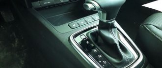
In cars with automatic transmission, the tachometer connection circuit sends a signal to the control module. Electronics will not allow the motor to go beyond the permitted limits.
If your device stops showing signs of life, diagnostics are necessary. How to check the tachometer at home?
In cars equipped with an OBD II interface, the check is carried out using a scanner. Also, the electronic tachometer can be checked using any pulse generator. We use an oscilloscope, frequency meter, or a known-good device as a standard.
The mechanical tachometer is checked using a drill or screwdriver. It's good if there is a speed controller. The cable shank is mounted in a socket, and the device body is rigidly fixed.
Repairing a tachometer is not such a difficult task if it is not an electrical circuit module. After localizing the fault, the faulty component is replaced.
Wiring, sensor contacts, the sensor itself, a torn magnet on the crankshaft. As a rule, the cause of failure is precisely these parts.
Mechanically it's even easier. You just need to replace the worn-out unit with a new one, or one purchased at the car market.
Cars with manual tachometers are usually heavily used, so finding a used part is not difficult. Connecting the tachometer after repair does not require calibration.
Gasoline devices also differ in the number of cylinders
While operating a car, you need to know how to check the tachometer at home. Most cars are equipped with a speedometer, pressure gauge, coolant temperature sensor and tachometer. They are installed differently depending on the make and model of the car. Sequencing:
- Check the tachometer before driving, carefully inspect the sensors. The dial usually shows single or double digit numbers, which are limited by the red stripe of the permitted operating limit.
- Start the car. Press the brake pedal with your right foot and turn on the ignition key. The tachometer reading should rise before stopping at the engine idle speed.
- Press the gas pedal and pay attention to the behavior of the tachometer.
- Monitor the readings while driving in each gear and when switching to the next.
- Avoid excessive motor overload. The red line on the scale represents the highest number of revolutions the engine can safely handle.
- If you need to further measure the vehicle's RPM to help diagnose the problem, use a handheld tachometer that measures the RPM while running.
Meter circuit
This meter is non-contact because it is enough to get close to, for example, a rotating motor shaft, on which there is a noticeable bright mark along the axis (a white line or white electrical tape), and after some time we get the numbers of pulses per second, and converting this into a revolution is already ordinary mathematics from elementary school. There is no conscious conversion done here so that you can measure the frequency of everything that emits light - monitors, LED displays, and so on.
This is the first mode, while the second is a simple counter of pulses (up to 65535) or objects moving in front of the counter. The modes change immediately after turning on the power when the number “1” is displayed. A long press of the button changes the mode to “2”. Holding it down again returns to “1”.
Recommendations
- An electronic tachometer is recommended for use by inexperienced drivers
who do not know how to navigate by engine sounds; - When purchasing, pay attention to the back of the package, where it is written for which brands of cars it can be used. Otherwise, the readings will be false or prepare for problems in the electrical circuit (this applies more to injectors);
- Install the module itself somewhere in a visible place so that you can always see its readings without any problems. As practice shows, installation is carried out on the central panel of the torpedo. Some people manage to place an oblong module in the instrument panel in place of the “STOP” indicator; this is for models 2108, 2109, 21099
.