A modern car is a whole complex of various technical and engineering solutions. Thanks to the coordinated work of all units, devices and mechanisms of various types, it is ultimately possible to obtain a reliable, economical and comfortable vehicle.
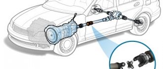
As you know, the main components of a car are considered to be the power unit and transmission. In fact, the engine produces the power while the transmission converts the torque and sends it to the wheels.
At the same time, an important element in the design of many cars is the hypoid transmission. Next, we will talk about what hypoid gears are, what types of such gears there are, how such a gear works, and what are the pros and cons of such a solution.
What is a hypoid gearbox
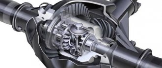
A hypoid gearbox is used to transmit rotation between intersecting shafts.
This is a mechanism in which the gear axes intersect the plane of the ring gear at a point that is below the axle and above the outer edge of the ring gear. Or, on the contrary, at a point above the axis and below the outer edge of the ring gear. The teeth, which have hypoid wheels, gradually decrease in height, from the outer to the inner diameter.
The gearbox may have one or several stages. Their task is to increase the gear ratio. Although the hypoid gear is one of the types of worm gears, its efficiency is 25% higher than that of the direct worm gear.
It is important to know! The hypoid gears have a single-stage gear ratio of up to 15:1.
Gearboxelectric motor
KM 063 V - 20.25 - FA1 - SS1 - 71B5 B3 - 0.37-4P / 1
| KM | 063 V | 20.25 | FA1 | SS1 | 71B5 | B3 | 0.37-4P | / 1 |
| 1 | 2.1; 2.2 | 3 | 4 | 5 | 6 | 7 | 8 | 9 |
| № | Decoding | Comments |
| 1 | Series designation: KM | Code for gear units series: KM |
| 2.1 | Size 050, 063, 075, 090, 110, | Specification code of gear units 050 063 075 090 110 |
| 2.2 | B: 2-stage C: 3-stage | 1 .B:Means 2 stages 2.C:Means 3 stages |
| 3 | Gear ratio | Speed ratio of reducer i |
| 4 | No marking means no output flange 2.FA,FB,FC,FD,FE(1/2) | 1 .No mark means without output flange 2.FA4 FB4 FC4 FD4 FE(1/2):output Flange and position |
| 5 | No marking means no output shaft. SS(1/2) output shaft on one side DS - double-sided output shaft. | 1 .No mark means hole output 2.SS(1/2):Single output shaft and position 3.DS:Double output shaft |
| 6 | 1. Dimensions of the input (motor) flange 2. HS indicates the presence of a high-speed input shaft | 1.Input flange code(63B5s 71V5ch 71B14) 2.HS:means shaft input |
| 7 | Location option (installation method) | Installation position code |
| 8 | 1.No marking means no motor 2. Motor power and number of poles | 1.No mark means without motor 2.Model motors(poles of power) |
| 9 | Electric motor terminal box location option | Position diagram for motor terminal box default position 1 not to write out is ok |
When ordering, please inform the company manager whether the gearbox requires an electric motor. Otherwise, the electric motor is not installed.
* Example: KM063C - 63.33 - FA2 - 80B5
Modifications of KM series equipment
Assembly drawing
| 1 | Hex screw | 22 | Frame | 43 | Bearing | 64 | Pad |
| 2 | Inlet flange | 23 | Key | 44 | Pad | 65 | Bearing |
| 3 | Clutch | 24 | Gear-shaft | 45 | Retaining ring | 66 | gear |
| 4 | Retaining ring | 25 | Bearing | 46 | Cuff | 67 | Gear-shaft |
| 5 | Bearing | 26 | Bearing | 47 | Outlet flange | 68 | Key |
| 6 | Retaining ring | 27 | Cork | 48 | Hex screw | 69 | Cork |
| 7 | Cuff | 28 | Retaining ring | 49 | Cuff | 70 | Retaining ring |
| 8 | Cork | 29 | Gear-shaft | 50 | Retaining ring | 71 | Sealing gasket |
| 9 | Hex screw | 30 | Retaining ring | 51 | Bearing | 72 | Key |
| 10 | Frame | 31 | Washer | 52 | Cork | 73 | Key |
| 11 | Cuff | 32 | Pad | 53 | Frame | 74 | Double sided shaft |
| 12 | Hex screw | 33 | Bearing | 54 | Cork | 75 | Key |
| 13 | Lid | 34 | Hex screw | 55 | Spacer | 76 | Key |
| 14 | Key | 35 | Frame | 56 | Gear | 77 | Sealing gasket |
| 15 | Clutch? | 36 | Cork | 57 | Key | 78 | Retaining ring |
| 16 | Bearing | 37 | Bearing | 58 | Shaft with hole | 79 | Retaining ring |
| 17 | Retaining ring | 38 | Key | 59 | Bearing | 80 | Sealing gasket |
| 18 | Bearing | 39 | Gear-shaft | 60 | Retaining ring | 81 | Key |
| 19 | Retaining ring | 40 | Breather valve | 61 | Cuff | 82 | Single-sided output shaft |
| 20 | Hex screw | 41 | Tablet | 62 | Cuff | 83 | Key |
| 21 | Cork | 42 | Cork | 63 | Retaining ring | 84 | Key |
KM.. (IEC).. / Performance parameters
| P1n = 0.12; 0.18; 0.25 | P1n = 0.37; 0.55; 0.75 | P1n = 1.1; 1.5; 2.2 | P1n = 3.0; 4.0; 5.5; 7.5 |
Types of lubricant and volume of oil to be filled
| Ambient temperature (C?) | ISO Viscosity Grade | SHELL | MOBIL | B.P. | Lubricant type | |
| KM.. | -10 ~ +40 | VG220 | Shell Omala 220 | Mobil gear 630 | BP Energol GX-XP 220 | Mineral oils |
| -20 ~ +25 | VG150 VG100 | Shell Omala 100 | Mobile gear 627 | BP Energol GX-XP 100 | ||
| -30 ~ +10 | VG110-46 VG32 | Shell Omala T32 | Mobil DTE 13M | |||
| -40 ~ -20 | VG22 VG15 | Shell Omala T15 | Mobil DTE 11M | BP Energol HLP-HM 15 | ||
| -40 ~ +80 | VG220 | Shell Omala HD220 | Mobil SHC630 | Synthetic oils | ||
| -40 ~ +40 | VG150 | Mobil SHC629 | ||||
| -40 ~ +10 | VG32 | Mobil SHC624 |
| Gear units | Oil fill volume in liters - (L) | |||||
| B3 | B6 | B7 | B8 | V5 | V6 | |
| KM050B | 0.32 | 0.3 | 0.2 | 0.2 | 0.35 | 0.25 |
| KM050C | 0.48 | 0.46 | 0.45 | 0.48 | 0.52 | 0.46 |
| KM063B | 0.6 | 0.56 | 0.4 | 0.42 | 0.62 | 0.4 |
| KM063C | 1.1 | 1 | 1 | 1.1 | 1.3 | 0.9 |
| KM075B | 0.9 | 0.7 | 0.65 | 0.9 | 1.2 | 0.7 |
| KM075C | 1.5 | 1.5 | 1.45 | 1.5 | 1.8 | 1.45 |
| KM090B | 1.5 | 1.3 | 1.2 | 1.2 | 1.8 | 1.25 |
| KM090C | 2.5 | 2.3 | 2.1 | 2.45 | 2.8 | 2.2 |
| KM110B | 2.5 | 2.2 | 1.9 | 2.1 | 3 | 2 |
| KM110C | 4.7 | 4.5 | 4.3 | 4.7 | 5 | 4.5 |
Other important equipment characteristics
- Possible geometric combinations
- KM.. HS.. / Performance parameters n1 = 1400 r/min
- Dimensional parameters of equipment, measuring quantities
- Positional diagrams, installation and other characteristics of gearmotors
Principle of operation
The operation of a hypoid gearbox is as follows. The moment of force is transmitted from the engine of an industrial machine through the clutch, gearbox and through the cardan to the axis of the main gear. The main gear, according to its designed design, is installed parallel to the axes of the primary shaft of the mechanism engine, and in relation to the secondary shaft of the gearbox.
Due to the fact that the gear teeth have a curved shape, the moment of force that is transmitted is high. This increases the mechanical as well as dynamic performance of the mechanism by an order of magnitude, which affects performance. This also affects the smoothness of the work being done.
It is important to know! The use of non-hypoid oils for hypoid gearboxes is strictly prohibited!
Hyperboloid gear
Today, several types of gears are known, which differ in the type of gears used. These can be cylindrical, conical, hypoid, etc. We are currently interested in hypoid transmission.
The name hypoid is an abbreviation for the word hyperboloid. The principle of operation of such a system was developed back in the 20s of the last century, and the main goal of its development was to reduce weight in passenger cars. Thus, it came to replace the double gear.
Distinctive features
A hypoid gear is a helical type of gear. It differs from the more usual one in the shape of the teeth on the gears, which have a specific curvilinear or oblique shape, curved along a hyperboloid (a special geometric shape). They gradually decrease in height from the diameter outside to the diameter inside the gear.
This type of transmission is also distinguished by the presence of a displacement of the axis of the small gear relative to the large one. This displacement is carried out in strict accordance with certain geometric formulas and any deviation from the norm can lead to irreparable consequences.
Operating principle
This helical gear transmission is most often used in a car to change the direction of torque and its magnitude. This option significantly improves the main characteristics of the final drive. This system is installed on cars with rear-wheel drive, in which the main gear reducer and the engine are located parallel to the movement. The torque from the engine in such vehicles is supplied at right angles to the drive axle, which significantly improves the mechanical and dynamic performance of the vehicle.
Application area
Hypoid gearboxes are widely used in all sectors of industry and agriculture. Their production is constantly increasing, new modifications are being developed, and existing models are being improved. Today the market supplies gearboxes for general and special purposes. The former meet general requirements and are used in the industrial sector. They are used in various jobs involving heavy loads. They are also used in modern robotics, instrument making, large machine tools for various purposes, positioning drives, as well as in highly dynamic applications. Hypoid gearboxes are also used in printing machines.
They are also used in railway transport and industrial construction.
It is important to know! Hypoid gearboxes are not sensitive to small errors during installation.
Results
Today, hypoid gears are increasingly used in the automotive industry, despite their high cost. Most often they can be found in executive class vehicles, for example, in Infiniti, Lexus, etc.
But even in modern budget cars today you can increasingly find such transmissions. Here you just need to understand that with good care, such a horse will serve for a long time and without any problems.
Advantages and disadvantages
The advantages of the mechanism include:
- Compact size and light weight.
- Durable aluminum housing.
- High power rating.
- Minimum noise level during operation.
- Smooth operation compared to bevel gearboxes.
- Long service life.
- High wear resistance.
- No corrosion due to factory surface treatment.
- Ensuring high transmission accuracy.
- Accurate axial displacement.
- Reliable gear operation.
It is important to know! The hypoid gearbox differs from others in its output power take-off shaft.
The disadvantages of the gearbox often include the possibility of jamming, which occurs due to sliding along the contact line. To reduce this risk, special gear oils are used for hypoid gears, which must be changed on time. But at the factory, during manufacturing, technologists achieve high tooth hardness.
Among the disadvantages, note the fact that due to the asymmetry of the gearing, during reverse and forward rotation, the transmission operation is not the same. Also disadvantages include strong axial loads, which adversely affect the drive shaft. However, this has virtually no effect on the wear resistance of the mechanism.
Car device
As the name suggests, single (or single-stage) final drives consist of a single pair of gears (gears), which can be cylindrical, bevel with straight or spiral teeth, or hypoid. The use of one or another type of bevel gears is dictated by the vehicle’s layout features, the possibility of simplifying the design of units, and reducing the cost of their manufacture and operation.
Cylindrical final drives
Cylindrical final drives are widely used in front-wheel drive passenger cars with a transverse engine, for example the VAZ-2108, -09, -10 and others. In this case, the main gear is usually combined in one housing (crankcase) with the gearbox, which makes it possible to significantly simplify and reduce the cost of the transmission design. An example of the design of the final drive of a VAZ-2109 car is shown in Fig. 3, which shows a four-speed gearbox integral with the main gear.
The drive gear of the main gear, which is small in size, is usually integral with the secondary shaft of the gearbox; the driven gear is mounted on the differential cup.
The teeth of spur gears can be straight, oblique or herringbone. Gear ratios in such main gears can vary from 3.5 to 4.5 in order to reduce noise and overall dimensions.
Bevel final drives
This type of main gear is used when it is necessary to change not only the magnitude, but also the direction of the torque transmitted to the drive wheels. Bevel final drives with straight or (usually) spiral teeth are the simplest in design and most technologically advanced in production, therefore they are widely used in passenger cars with rear-wheel drive and light and medium-duty trucks. Since the axes of the driving and driven gears in such gears lie in the same plane and intersect, such gears are called coaxial bevel gears. The advantages of coaxial bevel gears include high efficiency, manufacturability, relatively low requirements for the quality of lubricant and ease of maintenance. However, such gears have one significant drawback - their use in the design of a car does not allow reducing the location of the center of mass and the overall layout of the car body, which is a pressing issue for many cars and small trucks.
For this reason, bevel gears with intersecting gear axes are used as a single final drive for some cars and trucks, i.e. the wheel axes in such gears do not lie in the same plane and do not intersect. Such transmissions are called hypoid.
Hypoid final drive
Hypoid final drive is used on domestic cars GAZ-66-11, ZIL-431410, ZIL-133, Volga brand and many others. The axis of the drive shaft and drive gear in a hypoid gear is located below the axis of the driven gear by the amount “E” (Fig. 1, b), called hypoid displacement. This design of the final drive allows the driveline of a rear-wheel drive vehicle to be positioned lower and, thus, the layout of the entire vehicle is lower. At the same time, such an important performance indicator of the car as rollover resistance is improved, and it also becomes possible to lower the floor of the car, especially in the area of the “cardan tunnel”, which increases the comfort of passengers in the rear seat of a rear-wheel drive passenger car.
Sometimes in multi-axle cars the “E” offset in hypoid gears is made upward, which makes it possible to make the drive shaft through, and on front-wheel drive cars this design makes it easier to meet the layout conditions. The “E” offset is usually made within the range of 30...45 mm depending on the size of the gear.
In hypoid gears, the teeth of the gears have a spiral shape, due to which an increase in the contact area of the teeth, quiet operation and strength indicators of the gear are achieved. However, with this design of the bevel gear, the friction forces between the surfaces of the gear teeth significantly increase, the effect of transverse and longitudinal sliding of the teeth appears in the contact zone, which is why in hypoid gears it is necessary to use additional hardening of the surfaces of the gear teeth and special lubricants to increase their service life . Sliding of teeth leads to a decrease in transmission efficiency and even the possibility of its jamming (if the permissible load is exceeded), and the use of relatively expensive lubricants leads to higher maintenance costs, which is one of the disadvantages of hypoid gears.
The advantage of hypoid gears is smooth running and low noise level during operation, but such a disadvantage as longitudinal sliding also has a positive side, since it improves the running-in of the teeth of the gear wheels.
Increasing the tooth contact area makes it possible to reduce the size of the drive gear, since during transmission operation the load on each tooth decreases. In addition, as mentioned above, the use of hypoid gears allows you to adjust the layout of the transmission and the overall layout of the vehicle.
How to choose
There are a considerable number of hypoid gearboxes on the market. These are well-known companies, and vice versa. So how do you choose a mechanism? A qualified employee will help with this. Incorrect calculations can cause damage to the gearbox and related equipment. A competent choice of gearbox will help to avoid further costs for repairs and the purchase of new equipment. The main characteristics for choosing a gearbox are its dimensions or standard size, gear ratio and kinematic diagram.
As a rule, a gearbox with a hypoid transmission lasts 10-15 years. Nowadays it is difficult to buy a “bad” mechanism that will last less. This is due to similar production technologies.
You can rely on the price, because, as is commonly believed, the more expensive the better. However, more often than not you overpay for the brand rather than for quality. After all, almost all hypoid gearbox housings are made of durable aluminum, and the shaft hangers are made of casting or steel. But, since complex technologies are used to manufacture hypoid gearboxes, their cost is quite high.
Features of hypoid gearing or why you shouldn’t pull the car in reverse
A modern car is a whole complex of various technical and engineering solutions. Thanks to the coordinated work of all units, devices and mechanisms of various types, it is ultimately possible to obtain a reliable, economical and comfortable vehicle.
As you know, the main components of a car are considered to be the power unit and transmission. In fact, the engine produces the power while the transmission converts the torque and sends it to the wheels.
At the same time, an important element in the design of many cars is the hypoid transmission. Next, we will talk about what hypoid gears are, what types of such gears there are, how such a gear works, and what are the pros and cons of such a solution.
Is it possible to mix transmission fluids?
To understand this issue, you need to understand that even oils that have similar performance properties and are produced by the same manufacturer may have different chemical compositions.
So, for example, in the general case, such materials can be made on a mineral or semi-synthetic basis. The composition of the additives used is even more diverse. When mixing oils of different brands, these components can interact with each other and enter into chemical reactions.
The products of these reactions change, sometimes radically, the original properties of the original oils.
Most often, the combination of different oils leads to increased foaming of the product, which significantly worsens lubrication parameters and leads to increased heating of transmission components.
Thus, it is better to refrain from mixing oils of different groups. In exceptional cases, you can add oil of the same classification group.
Advantages and disadvantages of hypoid transmission
This type of transmission is becoming increasingly widespread in the automotive industry. Initially, they were used only in premium models, but today they can also be found in cheaper versions of vehicles. This happens due to very good performance during operation.
The main advantages of hypoid gears include
- Good wear resistance. Due to the specific structure of the teeth, a noticeable reduction in the load that falls on one tooth is achieved, which means that the gears will work longer.
- It was possible to significantly lower the driveshaft and reduce its channel in the cabin. This made it possible to evenly distribute the vehicle's center of gravity and also improved its stability.
- Such cars have very good stability and a smooth ride, which is also very much appreciated by modern drivers.
- Very low noise level. This effect is achieved due to the fact that during operation of the main gear, several teeth are simultaneously engaged. Owners of such cars note an excellent acoustic effect and driving the car becomes much more comfortable.
SAE
Marking of transmission lubricants according to the viscosity index - SAE - has become widespread throughout the world.
Developed in the United States, the SAE J306 standard classifies transmission lubricants based on viscosity when operating vehicles at extreme temperatures: low and high.
Using this qualification, you can determine the temperature range in which a certain lubricant is allowed to be used for a manual transmission and drive axles.
Recommendations for the viscosity of transmission oils that can be used for manual transmissions and drive axles of a vehicle are indicated by the manufacturer in the user manual.
Based on these recommendations, the car owner selects transmission fluid from among a range of lubricating fluids.
When choosing a lubricant, you should take into account the lowest and highest temperatures at which the car will be operated. SAE J306 classification takes into account the viscosity index at extreme temperatures.
The low temperature viscosity limit value corresponds to the temperature at which a Brookfield dynamic viscosity of 150,000 centipoise (cP) is achieved.
To determine the indicators, real tests were carried out with units of various designs. If these values were exceeded, the gear bearings on the shaft were destroyed.
Therefore, it is important to follow manufacturers' recommendations for low temperature application limits.
The value of the high-temperature limit is determined by readings of the kinematic viscosity of the lubricant at a temperature of 100 degrees. This indicator helps to approximately determine how much load the protective oil film can withstand and how sufficient it will be to protect the gearbox mechanism under heavy loads and at high operating temperatures.
According to the SAE classification, lubricants are divided into 9 classes, similar to motor oils:
All-season oils are marked using both markings, the first is winter, the second is summer, for example, SAE 75W-85, SAE 85W-90, etc.
SAE classification table for gear lubricants by viscosity index:
| Viscosity grade | Max temperature for viscosity 150,000 cP, degrees | Kinematic viscosity at a temperature of 100 degrees, mm2/s | |
| no less | no more | ||
| Winter | |||
| 70W | -55 | 4,1 | — |
| 75W | -40 | 4,1 | — |
| 80W | -26 | 7,0 | — |
| 85W | -12 | 11,0 | — |
| Summer | |||
| 80 | — | 7,0 | 11,0 |
| 85 | — | 11,0 | 13,5 |
| 90 | — | 13,5 | 24,0 |
| 140 | — | 24,0 | 41,0 |
| 250 | — | 41,0 | — |
The use of seasonal lubricants is not economically profitable, since transmission fluids have a long service life. If you use seasonal lubricants, they have to be changed before they have exhausted their service life. Therefore, all-season ones are more popular.
How are gear oils classified?
The variety of requirements for transmission oils, the various conditions of their use and the abundance of brands lead to the need to generalize the specifications of oil manufacturers and consumers and create a unified classification system for their designation.
Currently, several classifications of such liquids are in effect abroad. The most famous of them are SAE and API.
Most often, manufacturers indicate on labels the designation for both of these systems. Russian oils are most often classified according to GOST.
Purpose, design features
The main task of this element is to change the torque before applying it to the wheel drive. The gearbox does the same, but it has the ability to change gear ratios by engaging certain gears. Despite the presence of a gearbox in the design of the car, the torque output from it is small, and the rotation speed of the output shaft is high. If you transfer rotation directly to the drive wheels, the resulting load will “crush” the engine. In general, the car simply will not budge.
The final drive of the car provides increased torque and reduced rotation speed. But unlike a gearbox, its gear ratio is fixed.
The location of the final drive using the example of a conventional manual transmission
This transmission on a passenger car is a conventional single-stage constant mesh gearbox, consisting of two gears of different diameters. The drive gear is small in size and is connected to the gearbox output shaft, that is, rotation is supplied to it. The driven gear is much larger in size and it supplies the resulting rotation to the drive shafts of the wheels.
The gear ratio is the ratio of the number of gear teeth in the gearbox. For passenger cars this parameter is in the range of 3.5-4.5, and for trucks it reaches 5-7.
The higher the gear ratio (the greater the number of teeth on the driven gear relative to the drive gear), the higher the torque supplied to the wheels. In this case, the tractive effort will be greater, but the maximum speed will be lower.
The main gear ratio is selected based on the performance indicators of the power plant, as well as other transmission components.
The final drive design directly depends on the design features of the car itself. This gearbox can be either a separate unit installed in its own housing (rear-wheel drive models) or be part of the gearbox design (cars with front-wheel drive).
Final drive in a rear-wheel drive car
As for some all-wheel drive cars, they may use a different layout. If in such a car the location of the power plant is transverse, then the main gear of the front axle is included in the design of the gearbox, and the rear axle is located in a separate housing. In a car with a longitudinal layout, the main gears on both axles are separated from the gearbox and transfer case.
In models with a separate main gear, this gearbox performs one more task - it changes the angle of rotation by 90 degrees. That is, the gearbox output shaft and wheel drive shafts are perpendicular.
Audi front axle final drive location
In front-wheel drive models, where the main gear is included in the gearbox design, these shafts are parallel, since there is no need to change the direction angle.
A number of trucks use two-stage gearboxes. It is noteworthy that their design can be different, but the most widespread is the so-called spaced layout, which uses one central gearbox and two wheeled (on-board) gearboxes. This design allows you to significantly increase the torque and, accordingly, the traction force on the wheels.
Drive cars
The peculiarity of the gearbox is that it evenly divides the rotation between both drive shafts. For straight-line motion, this condition is normal. But when cornering, the wheels of the same axle travel different distances, so it is necessary to change the rotation speed of each of them. This is the job of the differential used in the transmission design (it is installed on the driven gear). As a result, the main gear supplies rotation to the drive shafts not directly, but through the differential.
General information
The main gear with a differential and axle shafts drives the drive wheels, the schematic diagram of which depends on the type of suspension guide device (Fig. 1).
Fig.1. Drive to the driving wheels of the vehicle:
A
– with a rigid beam;
b
– with a sprung main gear and an additional rigid axle;
c
– with sprung main gear and independent suspension.
In the case of a solid bridge beam (Fig. 1- a
) the main gear housing can be attached directly to the beam or be its integral part, and the axle shafts are shafts that are fully or partially relieved from lateral forces from the wheels. This scheme has become widespread due to the simplicity and low cost of the design. However, in this scheme there are large unsprung masses, which leads to increased inertial loads on the elastic and shock-absorbing suspension components.
The final drive housing can be mounted on the frame or base of the supporting body. The bridge beam ensures parallel and coaxial arrangement of the wheels (Fig. 1- b
). The axle shafts do not experience lateral forces and are shafts with two cardan joints. The axle shafts must have a sliding spline connection to compensate for changes in the distance between the hinges with relative movements of the bridge and frame. In such designs, while maintaining the dependent suspension, the mass of unsprung parts is reduced.
The main gear housing can be mounted on the frame, and the wheels move independently of one another (Fig. 1- c
). Depending on the suspension design, the wheel can move parallel to the plane of symmetry of the car or swing in an arc relative to a fixed axis intersecting with the axis of the main gear. In the first case, the axle shafts do not experience lateral forces and are shafts with two cardan joints, and in the second case, the axle shafts usually carry a lateral load and have one universal joint, the center of which is located on the swing axis of the wheel.
The final drive with differential and axle shafts must meet the following requirements
:
- provide gear ratios corresponding to optimal traction qualities and fuel efficiency;
- maintain kinematic coordination with the suspension guide device, and in the case of a steered drive axle, with the steering drive;
- ensure low noise levels;
- do not create angular velocity fluctuations in the transmission;
- have small overall dimensions to allow a simple layout and provide the necessary ground clearance;
- have sufficient strength and rigidity with minimal weight.
What is the difference between hypoid oil and where is it used?
Not all motorists know what features hypoid oil is characterized by and where it is used. This lubricant is mainly used in transmissions, but the compositions are also suitable for mechanisms involved in vehicle steering. This is a separate group of lubricating fluids that have special characteristics and distinctive properties. With their help, it is possible to satisfy the needs of the most demanding lubrication components. Hypoid oils are not used everywhere, but have special parameters necessary in certain situations.
Primary requirements
The GP consists of 2 gears. The drive shaft is smaller and is connected to the secondary shaft of the gearbox. The driven gear is larger in size than the drive gear and interacts with the differential and wheels of the car. Main requirements for transfer:
- lowest level of noise and vibration during operation;
- lowest gasoline consumption;
- increased efficiency;
- ensuring increased traction and speed parameters;
- manufacturability;
- smallest dimensions (to increase ground clearance and reduce the level of the bottom of the car);
- less weight;
- increased strength;
- minimal maintenance.
The transmission efficiency can be increased by increasing the quality of the teeth of the two gears and increasing the strength of the parts, as well as by using rolling bearings in the design.
Reducing vibration and noise during operation as much as possible is necessary for vehicle gearboxes. To do this, it is necessary to ensure good lubrication of the teeth. This will increase the accuracy of fastening the gears and increase the diameter of the shafts. It is also worth taking other measures to increase the reliability of the mechanism parts.