Print this article Font size 16
The design of any internal combustion engine, including VAZ 2109 engines with 8 valves, requires the following components:
- The combustion chamber;
- Valve mechanism;
- Cast lines;
- Exhaust manifolds;
- Intake manifolds.
If you bore and correct the current state of the manifold and cylinder head channels, you can increase the cylinder filling ratio, which leads to increased efficiency and engine power. It is not uncommon for modifications to be performed as the final stage in increasing the volume of the internal combustion engine.
Object of improvement
The combustion chamber
When studying combustion chamber tuning, it would be a good idea to read the article >> increasing the compression ratio as these types of tuning influence each other.
Space "ears" around the valves
If you intelligently modify the space in the combustion chamber that passes close to the valves when they open, you can significantly increase the throughput, thereby increasing the filling and power of the engine.
In a “two-valve cylinder”, if the combustion chamber has a compact structure, part of the circumference of the valve plates moves most of the way close to the edge of the combustion chamber, creating a low-flow area for the air-fuel mixture and for the release of burnt gases. If this zone is expanded, the filling of the cylinders can be increased and the power can be increased accordingly. In dome-shaped combustion chambers, or in block heads with a V-shaped arrangement of valves relative to each other, this processing technology is ineffective, since the valves, when opened, move towards the center of the cylinder and move away from the walls at a considerable distance. You need to bore to the places where the head meets the cylinder block and around the valves, creating the so-called “ears around the valves”. A gasket or an imprint of the old contact areas will help determine the area to which you can bore. Boring is carried out using cutters. Attention ! Bore very carefully, especially make sure not to get the rotating tool into the contact area of the block head seals.
Valve seat sag
Valve seats sometimes have a recessed location in the combustion chamber (Valve leakage can occur as a result of major repairs, high mileage, tuning associated with increasing valve lift by installing a different camshaft, etc.) At the beginning of the opening of the intake valve (by 1-2 mm) the air-fuel mixture will experience significant difficulty in penetrating the engine cylinders.
In the case of an exhaust valve, the ledge will interfere with the cleaning of exhaust gases from the cylinders in the final exhaust phase. The presence of irregularities and sharp corners greatly affects the “cylinder purging” (a very important phase of engine operation when both valves are open to a small amount). The situation can be corrected by smoothing all sharp edges around the valve seats. It is advisable to perform all operations on processing the combustion chamber with inserted (unnecessary) valves to protect the working edges of the valve seats from damage.
Valve seat projections
When installing valve seats into the block head, ledges are formed in the intake and exhaust channels due to the imperfection of the casting itself and the straight cylindrical shapes of the seats. The interfaces between stock parts are usually not processed in any way. Even if the factory provides for machining of the joints between the valve seats and the block head, it is carried out mediocrely with the formation of new ledges, since the machining only involves passing with a milling cutter, which does not provide the required quality when machining complex, curved surfaces. Smoothing the interface between the body of the cylinder head and the valve seats gives very good results in terms of reducing flow resistance and, as a result, increasing the filling of the engine cylinders.
Improved docking during modification of GRC valves
Poor-quality joining of these elements is one of the features of most VAZ models. Poor processing leads to air turbulence, which does not allow adequate air supply.
Refinement of a cylinder head of this kind includes getting rid of uneven surfaces by careful grinding. Before starting work, experts recommend installing the collectors on the joints, since the standard mounting option allows for possible displacement. If you work inattentively, this can lead to a negative result, which, naturally, must be avoided.
Increasing valve seat diameter
One of the most effective types of tuning for the cylinder head is considered to be increasing the diameter of the intake and exhaust valves.
The operation is very specific and requires the selection of new valves, valve seats and specific equipment to complete this procedure. The effect of enlarging the valves can also be achieved by boring the diameter of the valve seat by a certain small amount (depending on the circumstances). The working place of the valve seal is shifted to the edge of the valve plate. The maximum amount by which seats can be bored depends on the specific engine, the thickness and diameter of the seat. Typically, the smaller the valves and the more advanced the engine, the smaller the seats can be bored. In any case, if you increase the diameter of the seat by 0.75 - 1.2 mm, the reliability of the engine will not suffer from this, but the throughput will increase, as from a similar increase in the diameter of the valve with seats.
By the way, if the inner diameter of the seats is increased, then it is not necessary to leave the old valves; you can replace them with new ones with a larger diameter of the plate.
Cylinder head boring
Another problem of the domestic automobile industry is the presence of excess casting in the area of the guide bushings. This reduces their already small cross-sectional size. Using special ball cutters you can get rid of this disadvantage. Cylinder head boring should be done extremely carefully so as not to spoil the entire system.
It is important to know that the inner surface of the bushings cannot be made perfectly smooth, as this will lead to a deterioration in fuel evaporation. The result of this stage of tuning the VAZ cylinder head should be a perfectly round cross-section without the presence of factory casting residues. Next to this element there are other important components of the vehicle. For example, oil channel, cooling channel. Therefore, when boring the cylinder head, it is important not to damage them.
The video shows the boring of a 16-cl. cylinder head. and valve:
Refinement of the cylinder head - changing the dimensions of the valve system section
This type of VAZ cylinder head tuning solves two issues:
- Increases the cross-section of the valve system.
- Reduces all of these elements.
Unfortunately, this process will not be complete without some investment, since such modification of the cylinder head requires replacement of the guide bushings. The consequence of such an upgrade, in addition to throughput, will be a reduction in the weight of the system to forty percent of the original.
Docking the collectors with the head
The need to adjust the internal surfaces of the intake and exhaust manifolds to similar channels of the block head is due to their inaccurate manufacturing and lack of adjustment during the assembly process at the manufacturer. However, a smooth transition from the manifold to the head bores is very important for good engine filling. If all the ledges are removed, the flow of the fuel-air mixture will encounter fewer obstacles on its path and a larger amount of the mixture will enter the engine cylinders.
Adjacent surface of the intake manifold
The adjacent surfaces of the intake manifold and the cylinder head must be carefully processed until a complete fit is achieved.
To begin with, it is advisable to place the manifold on pins to firmly fix the manifold relative to the block head. Next, mark the places of inconsistencies with a “marker” (alternatively, coat the surfaces with paint, separate them after drying, when broken, the places of metal protrusions on both surfaces will be visible) To prevent the marks from being erased, scratch along the contour with an awl, then treat the surfaces with cutters until a complete joint is obtained. 2 Method. Use plasticine
1. Apply plasticine to the docking area and partially inside the cylinder head channels. 2. Sprinkle with fine shavings, dust, etc. A separating material is needed to prevent the surfaces from sticking together when joining. 3. Attach the manifold to the cylinder head and tighten with bolts until the plasticine is not completely squeezed out of the crack. There should be 0.5-1mm left 4. Disconnect the manifold and the prints will show where the cylinder head material protrudes. 5. Draw a line with an awl and cut off the excess with cutters. 6. Repeat the procedure for the manifold, since the first 5 points determine the protrusion zone of the cylinder head only.
Operations to identify processing sites (metal removal), block heads for better docking with collectors.
3 Method. Use the manifold gasket. The gasket must be applied alternately to the mating surface of the cylinder head and manifold. When marking the places where metal will be removed, pay special attention to the accuracy of the alignment of the fastening holes or pins, since they are landmarks.
I’ll deviate a little from the topic and note that it would not be superfluous to dock and smooth out all the sharp ledges of all the parts located at the inlet, since they create very significant resistance to the flow of the air-fuel mixture.
Parts that create intake resistance for injection or carburetor systems:
— Steps connecting the throttle to the intake manifold and the intake manifold — Imperfect shape of the throttle valve — Imperfect shape of the mass air flow meter — Imperfect shape of the intake manifold — Corrugated intake manifold — Air filter — Carburetor junction with the intake manifold and thermal insulating insert
Exhaust manifold contact surface
If the exhaust manifold has the same internal diameters of the pipes as those on the cylinder head, then they also need to be joined. if the holes in the exhaust manifold pipes are significantly larger than the holes in the cylinder head, then there is no need to bore the head, because this measure was made specifically to limit the back pressure from the exhaust system back into the cylinders. (the exhaust gases experience significant resistance when meeting the step formed by the smaller hole on the cylinder head.)
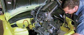
Modification of the VAZ cylinder head
Car enthusiasts, regardless of how long they have owned a car, are constantly looking for ways to increase engine power. There are several options for improving your car, one of which is modifying the cylinder head (cylinder head).
We know that torque, and therefore power, are directly dependent on such an indicator as the coefficient of filling the cylinders with the working mixture.
The higher the filling, the greater the engine power, which increases as the maximum torque value shifts to higher speeds. To achieve this, camshafts with extended intake/exhaust phases and increased valve lifts are installed, but in practice this is not enough. If we take a critical look at the cylinder head, we will see many shortcomings - seemingly small, but they are the ones that prevent the full potential of the engine from being realized. This is due to the manufacturing technology used in mass production of the cylinder head, and therefore everything will have to be corrected yourself or in a tuning studio. How exactly? Let's talk about this. Docking of cylinder head channels and manifolds
The most noticeable “blunder” of our manufacturers can be called the inaccurate joining of the holes of the cylinder head channels and manifolds. We remember from physics lessons that any bump in the path of the air flow causes the appearance of turbulence, and, consequently, a decrease in its speed. Here we have whole “steps” that we absolutely must get rid of. At the same time, it is necessary to check the gaskets under the manifolds so that they also do not create obstacles. It is advisable to place the collectors on pins before starting work. This is necessary for the reason that the fastening of the manifolds on VAZ cars allows for a slight displacement of the planes of the cylinder head and manifolds relative to each other, which can lead to a zero result. We find places on the cylinder head and manifolds (2 pins for each at the edges) for convenient drilling. We place the metal pins tightly in the cylinder head, but the manifolds should fit onto them easily, but without play. Make the necessary holes in the gasket. Now accurate positioning of the manifolds and cylinder head is ensured.
It should be taken into account that if the diameter of the cylinder head channel is slightly larger (1-1.5 mm) than the diameter of the intake manifold channel, but their coaxiality is the same, then this can be neglected, since this will not create any significant resistance. At the exhaust, a similar situation is created, only the cylinder head channel can now be slightly smaller than the exhaust manifold channel.
Cylinder head inlet/exhaust ports
If you carefully examine the intake/exhaust channels of the factory cylinder head, you will immediately notice the casting tides in the area of the valve guides, the bushings protruding into the channel and, in places, the broken shape of the narrow channels. Using ball cutters of different shapes and sizes, it is necessary to increase the flow area of the channels and remove all irregularities and protruding parts. The shape of the channel must be changed so that its bend is as smooth as possible, but maintains certain radii of curvature. The inner surface of the intake channels is left slightly rough for better evaporation of gasoline from their walls. The exhaust channels can be polished, although this will not give a noticeable effect. The cross-section of the channel should not be a regular circle. The intake port is elliptical in shape with a slight barrel-shaped extension in front of the valve seat. The rest of the cylinder head channel and intake manifold gradually tapers in the direction of flow.
When increasing the diameter of channels, it is necessary to take into account nearby internal communications. If you work carelessly, you can damage the oil channel or the cooling jacket channel. When working with the cylinder head of eight-valve engines, which are used in front-wheel drive VAZs, you must be extremely careful. Although this will not save you when boring one intake channel, in which the oil channel runs so close that its opening is inevitable. Unfortunately, even if the channel remains unopened, it may simply be covered with a thin layer of aluminum and later break through under the oil pressure of a running engine. Before starting boring, it is advisable to drive a steel bushing into the oil channel, but, unfortunately, this is not the most convenient option. It is better to install steel or aluminum bushings after opening the channel, or weld the channel with argon. First, decide whether to start boring from the manifold or cylinder head. If you plan to significantly increase the diameter of the channels, then it is better to start refining from the part whose channels have thinner walls, and then the channels of the mating part are bored according to their shape and position. In classic VAZ engines, it is customary to start boring from the manifold, because the cylinder head channels have sufficient thickness for subsequent alignment. Note the parts of the valve guides that protrude into the channels. They create noticeable obstacles to the flow, so they try to shorten or sharpen them. Sometimes the bushings are ground flush with the wall of the channel and, although this better optimizes its throughput, such modification reduces the service life of the guides, which are already short on forced engines.
Valves
Here the improvements are aimed at increasing the throughput and reducing the weight of the valves. The throughput can be increased by changing the profile of the plate, as well as the working and additional chamfers of the valve. When regrinding valves, excess metal is removed from both sides of the valve plate. A small notch is made on the front side, and on the back side the radius of the transition of the rod into the plate is reduced. The valve plate and stem are also thinned. If you do not plan to change the bushings, then remove the excess metal from the valve stem from the poppet to the guide bushing. Reducing the diameter of the entire leg will require replacing guide bushings with a smaller hole diameter. On 8-valve VAZ engines, by reducing the diameter of the valve stem from 8 to 7 mm, you can achieve a reduction in the weight of the rod by 23.5%. For 16-valve engines, the stem diameter is initially 7 mm. You can supply titanium-aluminum valves, which are 40% lighter than steel, but they are very fragile and expensive. In this case, the seats have to be replaced with bronze ones, which are softer compared to cast iron, which leads to a decrease in valve rebound when closing and additionally dampens shock loads. On 8-valve VAZ engines, the working chamfers are made narrower, the exhaust angle is changed to 45º, and the intake angle is changed to 30º. In the places where the valve plate transitions into the working chamfer, additional chamfers are cut, which gives an increase of about 5-6%.
Further refinement involves replacing the valves with larger models. Sometimes they can be installed without replacing the seats, since the standard ones allow you to slightly increase their internal diameter and the diameter of the working chamfer. This is practiced on 16-valve cylinder heads 2112, on which enlarged 32/27 mm valves are installed. It is also possible to install larger valves, which involves replacing the seats. In this case, the original saddles are cut out and larger cast iron, bronze or metal-ceramic ones are installed. The necessary chamfers are cut into them and valves of an even larger diameter are installed than those previously discussed. This method is more expensive than the first, but the most effective, and for 8-valve cylinder heads of VAZ cars it is the only solution. The increase in power with this modification reaches 8-10%. In this case, you can install lightweight, enlarged valves 39/34 mm. So that you can better navigate, we will provide data on valves that can be installed on VAZ engines:
- — VAZ 2101, 21011, 2103, 2106, 21213, 21214, 2123 – valves from 39/34 to 42/35;
- — VAZ 21083, 2111, 21114, 21116, 11183, 11186 – valves from 39/34 to 40/34;
- - VAZ 2112, 21124, 21126, 21127, 21128, 21129 - valves from 31/27 to 33/29,
where the numerator indicates the diameter of the intake valve plates, and the denominator indicates the diameter of the exhaust valves.
Of course, this is not the only solution, and you can select the sizes of the valve plates yourself, but you must take into account that for naturally aspirated engines, the optimal ratio of the exhaust valve area to the intake valve is ¾ or approximately 75%. This is clearly seen from the following data: 31/27 - 75.9%
33/29 - 77.2% 39/34 - 76.0% 40/34 - 72.3% 41/35 - 72.9%
If your car is equipped with supercharging or nitrous oxide injection, it Exhaust valves need to be enlarged as the engine produces more exhaust gases. For such engines, the valve ratio can be 90% or more.
Valve springs
Standard springs are calculated for a specific engine using a serial camshaft.
A sufficient safety margin is taken into account, designed for relatively low speeds. In classic engines, valves hang at speeds of more than 7000, on the VAZ 21083 higher speeds are allowed, and on the VAZ 2112, inadequate valve operation is possible at speeds of 7500-8000 rpm. Replacing the camshaft with a higher camshaft can lead to stuck valves.
The simplest way is to increase the preload of the standard spring, which is done by placing a washer under it. The force on the spring increases, but the free play decreases noticeably. When installing sports camshafts, more stringent requirements are imposed on the forces on the springs. In this case, a large cam lift and a corresponding spring stroke are required, so they are replaced with stiffer ones that have a larger compression stroke. Stiffer springs significantly increase the load on the valves, camshaft and discs, so it is advisable to carry out such modification as the last of all methods of increasing the valve sticking threshold. Another way is to lighten the valve spring retainers. Their lighter weight reduces the load on the camshaft and timing parts, which is especially important at high speeds. You can resharpen the standard plates, but it is better to install new ones made of titanium-aluminum alloy. Aluminum (D16T) plates are cheaper, but are subject to deformation in critical operating conditions. Titanium products are more durable, although some car enthusiasts are deterred by their price. Plates made of Al-Ti alloy from the manufacturer PRO.CAR have proven themselves well. Valve tappets
In VAZ 21083 and VAZ 2112 engines, the kinetic connection of the cylinder head valves with the camshaft is carried out using pushers. On cylinder head 21083 they are mechanical with adjusting washers, and on cylinder head 2112 they are hydraulic compensators. Standard pushrods have some limitations and are therefore unacceptable when working with sports camshafts. In this case, solid mechanical pushers are used, which have an increased diameter and do not require adjusting washers. To install them, it is necessary to bore the wells to the required size. The valves are regulated by selecting thrust bearings of the required size (or “sausages” - cut valve legs of different lengths), which is quite labor-intensive. The work of a specialist in adjusting valves with installed “solid valves” will not be cheap!
Valve Levers
On classic-type VAZ engines, the valves are driven from the camshaft by levers (so-called rockers). They are convenient and easy to adjust the thermal clearances of valves, but they are excessively massive and allow some deviation in the kinematics of valve movement. Also, in the “classic” cylinder head, the rocker can fly off its seat at extremely high speeds. To combat these shortcomings, the levers are lightened, light-alloy models are installed and stiffer valve springs are used.
Valve guides
Depending on the type of engine and expected operating modes, the design and material of the valve guides are selected. Reasons that may require modification or replacement of standard bushings:
- — When using valves with a smaller stem diameter;
- — When the part of the guide bushing protrudes strongly into the cylinder head channel;
- — If the shape or size of the opposite part of the guide does not meet the requirements;
- — If the thermal conductivity of the guide bushing is insufficient (replacement with bronze ones is possible).
Bronze is a good heat conductor, it removes heat well from the valve and effectively dissipates it into the cylinder head, therefore, on highly accelerated engines, the use of bronze guide bushings is extremely necessary. A good example of such products are bronze bushings produced by PRO.CAR. They have a slightly shorter service life compared to metal-ceramic products, but it all depends on the operating modes of the engine and the quality of the bushings themselves.
Combustion chamber shape
With this modification, you can significantly reduce the risk of detonation, improve cylinder filling and create conditions under which the fuel mixture will be better distributed, mixed and ignited. Detonation occurs in places farthest from the spark plug. This is explained by the fact that when the mixture ignites, the pressure in the combustion chamber (CC) increases sharply and leads to extreme compression of the mixture that has not yet ignited. This provokes its self-ignition, which is explosive in nature and leads to a sharp increase in temperature and pressure in the cylinder. Detonation occurs, characterized by metallic sounds and propagating through the engine in a series of shock waves of detonation explosions. Frequent occurrences of detonation lead to devastating consequences, so it is imperative to take measures to eliminate them. To do this, the sharp edges and corners of the combustion chambers are smoothed out as much as possible, casting errors are removed and the surface of the combustion chambers is polished, which additionally adds 5% of power by reducing heat losses. To improve cylinder filling and create optimal conditions for the fuel mixture, it is necessary, first of all, to pay attention to the shape of the combustion chamber around the valves. On VAZ 8-valve cylinder heads, the combustion chamber is wedge-shaped and the valve gap is “screened” by its steep walls. This leads to the fact that the flow of the working mixture is forced to overcome additional obstacles, which is clearly noticeable when installing larger valves. Therefore, the volume of the CV must be expanded around the valve. It is also necessary to modify the segment of the valve gap near the spark plug and make the interface of the bottom and vertical walls of the combustion chamber smoother. There should not be any steps or wells around the valve seats, and the conical recess of the valve seat should be no more than 30º relative to the bottom of the valve seat. The VAZ 2112 cylinder head initially has a hemispherical cylinder head, which minimizes all necessary modifications and eliminates the flaws of mass production.
Compression ratio
The compression ratio (CR) is the ratio of the total volume of the cylinder to the entire volume of the CV. The more compressed the fuel mixture is before ignition, the more work it will do subsequently. By increasing the coolant, we increase engine power, but there are also limiting factors, such as an increase in the load on the piston and the risk of detonation. Standard cast pistons of VAZ engines allow a coolant ratio of up to 11:1. The most noticeable positive effect from the increase in coolant is in engines with wide valve opening phases. This is due to the fact that the filling coefficient of naturally aspirated VAZ engines does not exceed 100%, that is, the dynamic coolant does not exceed the static coolant. Dynamic coolant is the volume of the fuel-air mixture entering the cylinder relative to the volume of the combustion chamber. When using wide-phase camshafts at low and medium speeds, the dynamic coolant is lower than the static one. An increase in coolant leads to a proportional increase in dynamic fluid, which has a positive effect on the power and economic performance of the engine. In this case, it is necessary to eliminate the prerequisites for the occurrence of detonation at the maximum cylinder filling ratio, which is achieved by increasing the octane number of the fuel and changing the composition of the fuel-air mixture. As engine speed increases, the duration of the combustion cycle decreases, which can lead to incomplete combustion of fuel and, consequently, loss of power. Therefore, by increasing the coolant, we speed up the combustion process, which allows us to get maximum power from the engine. As a result, most high-speed forced gasoline engines require an increase in coolant. After completing the cylinder head modifications that we discussed in this article, you will be able to fully unlock the potential of your car’s engine!
Enlarged inlet and outlet channels
Increasing the diameter of the inlet and outlet channels reduces the resistance to the movement of gases, but the speed of their movement also decreases. Which is good for high-speed engines and bad for a motor without calculating its operation at high speeds. Increasing the diameter of the channels is ineffective without increasing the diameter of the valves. In this regard, it is necessary to either bore and repress the seats for large valves, or bore existing seats by a small amount in order to increase the diameter in the valve area, and not just the channels themselves.
Cutting off part of the guide
The intake and exhaust valve stem sits in the middle of the ports, creating significant resistance on the intake and exhaust.
The situation is aggravated by the presence of a protruding part of the valve guides and the tide flowing around them. In “hard” tuning, all protruding parts are cut off, and the valve stem is ground to a smaller diameter. It is not recommended to reduce the valve stem by less than 10%. It is better to process the protruding end of the guide from the outside to obtain a more streamlined shape, this is more difficult and less effective in terms of filling, but cutting off part of the guide reduces its length and greatly increases wear, especially when using a camshaft with increased valve lift. When the guide protrusion is completely cut off, you can somewhat compensate for its wear by replacing conventional bushings with bronze ones, which have much higher wear resistance than conventional ones. Tuning valve guides
Machined valve guides for less flow resistance.
Complete cutting of the valve guides to ensure even better cylinder filling. To the detriment of the durability of the valve mechanism.
Combustion chamber parts
Modified intake and exhaust valve.
The combustion chamber. Piston crown. It is not visible to the naked eye, but under a microscope, the smooth metal looks like mountain ranges with a mass of protrusions and depressions. Polishing smoothes out these irregularities, thereby reducing the actual contact surface area. When polishing the metal, the contact area of the burnt gases with the surfaces inside the combustion chamber is reduced, due to which the heat transfer is reduced and the gases, when expanding, can do more useful work, because if the temperature of the gas decreases, its pressure also decreases, which leads to a loss of power.
You can learn more about heat losses by following the link >> Heat losses
Another plus arising from the first:
Since less heat is lost into the metal, the temperature of the working surfaces (piston, valves, combustion chamber) decreases, which has a beneficial effect on the engine’s knock resistance and resistance to overheating. Also, polishing and smoothing all sharp corners reduces aerodynamic drag during the movement of gases at the inlet and outlet. (especially when passing through narrow gaps, during the initial opening of the intake valve, purging, etc.) Polishing prevents carbon deposits, reduces stress concentration, reducing the possibility of cracks in the combustion chamber and valves. For those who find polishing difficult. Advice! Try polishing with a special felt wheel for an angle grinder. Costs about 100 rubles. At high speeds, using regular goya paste, polishing goes very quickly and is a lot of fun!
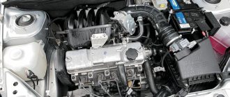
Modification of the cylinder head on the VAZ 2109 (8 valves)
The design of any internal combustion engine, including VAZ 2109 engines with 8 valves, requires the following components:
- The combustion chamber;
- Valve mechanism;
- Cast lines;
- Exhaust manifolds;
- Intake manifolds.
If you bore and correct the current state of the manifold and cylinder head channels, you can increase the cylinder filling ratio, which leads to increased efficiency and engine power. It is not uncommon for modifications to be performed as the final stage in increasing the volume of the internal combustion engine.
Object of improvement
What should not be polished
There is no need to polish the inlet and outlet channels. Firstly, due to inaccessibility, polishing internal channels is very long and tedious. Secondly, at the inlet, due to the very smooth surface, a film of gasoline is formed which periodically breaks off into the flow, forming uneven operation of the engine at low loads. Polishing has a particularly detrimental effect on an engine with a carburetor power supply system and single injection, since the air-fuel mixture moves through the entire intake tract, completely passing through the intake channels. For channels, a sanded smooth surface is sufficient, without unnecessary and sometimes harmful polishing.
The process of boring head channels
To complete the task of boring channels, you will need a ball cutter. The diameter of the cutter must correspond to the required bore size. It can be 29, 31 or 32 mm. Before creating channel geometry, keep in mind that it must ultimately match the geometry of the machined manifolds. To comply with this condition, it is important to connect the pipeline to the head and, in accordance with the resulting traces, set the desired geometry using the boring method. To achieve a clear mark, plasticine or solid oil is used, and the end part of the head is treated with these substances.
The channel boring procedure is performed until the following diameters are achieved:
- the size of the head inlet channel should be 3.1-3.2 cm;
- the diameter of the outlet channel will be 2.9 cm.
The boring process consists of the following steps:
- The head is being modified. The size is increased, as well as the geometry, if required. The measurement method is used to determine the required diameter of the roundings.
- Valve seats are being upgraded. Sharp edges are removed from these components because they create high resistance when the valves open.
- The holes on the intake manifold side are aligned with the head channels. Using a milling cutter, you need to bore the hole to the bushing. If inconsistencies remain, this will cause the combustible mixture to slow down.
- Boring is performed from the side of the combustion chamber. You need to make sure that the seats for the new valves are installed.
- The geometry is bored using cutters; for this, elements of different sizes are used.
- The final stage will be sanding the channels. The procedure is performed until the surface of the canals is as mirror-like as possible.