The design of the VAZ 2107 car provides for the presence of a specialized connector, the main purpose of which is to study the technical condition of the vehicle. Today, such devices are manufactured according to the same OBD2 standard. Moreover, the diagnostic connector on the VAZ 2107 of the OBD2 type has been installed since 1995, and before that, cars were equipped with OBD1 type devices. Let's take a closer look at what this device is and what its purpose is in the design of the seven.
Where is the diagnostic connector located?
The type of device in question, which is also called a diagnostic block, in the design of the 7 and other cars serves to check the condition of the vehicle for errors and malfunctions. After such manipulation, you can decide on the need to repair or replace parts and mechanisms.
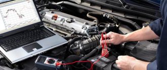
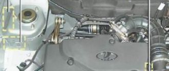
Structurally, the connector is a contact connection with a large number of pins. An autonomous source (computer) is connected to this connection, and a test event is carried out using special programs. On the seven, the diagnostic connector is located in the passenger compartment on the passenger side under the glove compartment. By the way, on many car models of domestic and foreign production, the connector is also located in this place.
To connect the computer to the car via the connection, you do not need to disassemble, remove or unscrew anything. The check can be carried out while inside the car, since the essence of this process is to identify errors in the operation of the engine.
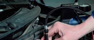
Knowing where the connecting element is located, figuring out the connection to the computer will not be difficult. To connect the computer to the car via the OBD2 connector, you will need a special cable with the appropriate plugs (connectors). However, there is an easier way to avoid buying a cable. To do this, you need to connect two contacts in the block so that the ECU displays error codes. Before connecting the contacts, you will need to understand the pinout of the block on the VAZ 2107.
Pinout of contacts of the VAZ 2107 diagnostic connector
It is known what a diagnostic block is and why it is needed in the design of the seven, so if you need to use it, you may need information about the pinout. Pinout is the designation and decoding of each contact. The design of the 7 uses 2 types of connectors - 12-pin rectangular and 16-pin trapezoidal. Determining errors can be done not only using a computer and special programs, but also with your own hands. To do this, you need to know the pinout in order to correctly connect the necessary contacts for test manipulations.
Let's look at what the pinout of each type of diagnostic pad is.
Rectangular 12-pin block
These types of devices were installed on all injection cars that were produced before 2002. Let's look at the designation of contacts:
- A is mass.
- B - engine diagnostic line.
- C - AIR.
- D - self-test lamp or potentiometer.
- H - 12V power supply.
- G - fuel pump control.
- J - socket for checking the condition of the airbags.
- M - engine and ABS check line.
Trapezoidal 16-pin block
After 2002, domestic cars began to be equipped with trapezoid-shaped pads, on which the number of contacts increased from 12 to 16. Let’s consider the purposes of the main tires:
- 2 - positive contact.
- 4 — body grounding.
- 5 - signal grounding.
- 10 - negative contact.
- 15 - diagnostic line.
- 16 - powered by 12V battery.
When you know what the diagnostic connector pinout looks like, it will not be difficult to diagnose the car yourself. Below is a diagram of the design of blocks with 12 and 16 contacts, as well as a plug, with the designation of the main contacts.
How is diagnostics carried out?
To perform diagnostics without special equipment, you will need to perform the following manipulations:
- Connect contact “B” to ground “A”.
- Turn the ignition to the engine start position, but do not start the engine.
- After this, the “Check Engine” warning light will show code 12. You can read it as follows: first, the light flashes briefly once, and after a short pause, flashes twice for 2 seconds. This code is read as "1" and "2", which results in "12".
- Code “12” means that the programs are working properly.
- After checking that the program is working properly, errors will be displayed (if any). You need to read errors using a similar checking principle.
The first message on the screen of diagnostic equipment or a computer that causes panic among beginners is usually something like “No connection”, “No controller response” or something similar, but no less intriguing. The motor tester, for example, begins to offer options - from unconnected power to a hardware malfunction of the adapter. It’s good if the car with the immobilizer was the first to arrive for diagnostics and you are sure that everything is in order with the adapter. The reason for the lack of communication on cars without immo is trivial and is possible only in the domestic auto industry - a break in the diagnostic line running from the diagnostic connector to the ECU. The immobilizer uses K-Line to communicate with the ECU and is included in the diagnostic line break. If the immobilizer is not installed, then the diagnostic line hangs in the air and there is no connection with the computer. Apparently there was supposed to be a plug in this place, but... To restore communication, you simply need to install a jumper between pins 9-1 and 18 of the immobilizer connector (or install an immobilizer) as shown in the figure. In practice, to preserve the functions of smooth dimming of light, and simply to scare away pioneers, these two wires are cut and spliced, leaving the immo in the connector.
GAS diagnostic connector.
1 +12V 2 +12V from battery 10 L-Line 11 K-Line 12 Ground
Diagnostic connector VAZ
A - GND B - L-Line (may not be) M - K-Line G - Fuel pump control.
H - 12V. Constant from the battery through a fuse. /may not be.
Where is the correct connector?
Most often it is located under the torpedo. By the way, it can be located on both the right and left sides. On certain models, the device is located near the steering column. Can be located to the left and below it. For cars that have a Europanel, the connector is located under the cigarette lighter.
Attention! The required connector can be covered with a decorative panel.
It is worth mentioning that two additional contacts, which are located on the diagnostic block of the VAZ 2114, are needed for the external air temperature sensor. After you make the connection, you will need to activate the K-line. It is necessary in order to transfer all important information to the device.
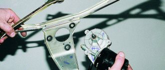
This is done as follows:
- The meter wire is connected to the second contact of the connector block.
- The second end is led to the diagnostic connector.
- The connection is made using the M-socket at the EURO 2 block, or to the seventh socket of the EURO 3 block.
- Connect the on-board computer and install it in the planned location.
Connector location
So, we plan to check our car and we even have the necessary equipment. Now you need to find the connector - it is located at the bottom of the steering column, to the right of the driver. This connector is also called OBD. Knowing this name, it will be easier to find a suitable adapter.
If you believe the reviews, the most successful adapter for VAZ cars is considered to be a device for connecting K-Line. It has a lot of free space, so you can connect almost any testing equipment to it.
As for the main diagnostic device, it will be a computer. Of course, it is easiest to work with a laptop, since the process can be performed right behind the wheel of a car. But if there is only a stationary option, then you should take care of a long cord connecting the computer to the adapter.
Basic steps in diagnosis
When you have found the VAZ 2114 diagnostic connector, you can begin the required diagnostic work.
By the way, before installing the device, think about what exactly it will be used for. When choosing an on-board device, you need to take into account the characteristics of the car, so inexpensive models are suitable for the VAZ 2114. It will be enough to choose a system that has a monitor, a set of wires, and the processor itself.
Next, you will need to find a place where you can mount the monitor. It is necessary to take into account the individual characteristics of the machine; the optimal place is the central part of the console. When there is not enough free space on the dashboard, you should mount the monitor on the dashboard.
Remember that you need to find a place for the processor, and it is important that the ventilation holes must be freely accessible. The case should be fixed in a certain place for greater reliability.
see also
The wires deserve special attention; they must not be damaged during operation. To do this, experts advise passing them through a special tube.
After the connector for diagnosing VAZs has been found, other work has been completed, and the wiring can be connected.
After the installation is completed, you can install the software and make the necessary settings.
Now you have access to car diagnostics.
Useful video
You can get more information about connecting to the diagnostic connector from the video below:
Any VAZ-2112 car is equipped with a system for self-diagnosis of faults, which can inform the owner about the presence of any fault without visiting a service station.
Such a system works by connecting special diagnostic equipment to it and further reading and decoding errors.
OBD 2 Review
OBD 2 is a vehicle diagnostic device that first appeared in the United States in 1996. In Europe, this standard has been adopted as mandatory since 2001. Thanks to its widespread implementation, errors on machines of different brands have the same appearance.
The standard code contains the X1234 structure, where each character carries its own meaning:
- X is the only letter symbol that allows you to recognize the faulty system (engine, gearbox, electronic components, etc.);
- 1 - represents the general OBD standard code or additional factory codes;
- 2 - clarification of the location of the malfunction (power or ignition system, auxiliary circuits, etc.);
- 34 is the serial number of the error.
A special feature of the connector is the presence of a power plug from the on-board network, which allows the use of scanners without built-in or additional electrical circuits. The first diagnostic protocols provided only information about the presence of a problem. Modern connectors allow you to obtain more data about a malfunction by connecting diagnostic equipment with electronic units in the car.
Each device must comply with one of three international standards:
The video from the channel Sanek Zhelezniy Kaput presents a video demonstrating testing of the SsangYong New Actyon car through the OBD 2 connector.
When is diagnostics required?
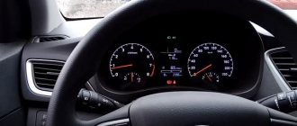
The first sign that the car system should be diagnosed will be the blinking of the CHECK ENGINE lamp located on the instrument panel. Please note that the presence of errors in the system will be the fact that after 10 seconds after starting the engine, the warning light will not go out and the error data will be stored in the ECU memory.
The error is indicated by an arrow.
Where is the connector?
In order to read all the fault codes that have arisen using diagnostic equipment, you will have to get to the diagnostic connector, which is located directly under the instrument panel console on the left side.
The location of the diagnostic block is indicated by an arrow.
You will detect it immediately as soon as you look at the approximate area of its location, since its characteristic shape is very specific.
Connectivity and scanners
There are different ways to connect to OBD II inputs. The most modern ones include devices equipped with Bluetooth. In this case, gaining access to the on-board system requires a minimum of time and hassle. For Renault Megane there is a convenient OBD II scanner ELM 327 with a Bluetooth adapter. To gain access from a mobile device, use the OBD CHECK Torgue program, available in the official Android Market.
Please note that this scanner does not work with all Renault cars. Limited functionality is available for cars since 2006, but the device does not see all the sensors on earlier models, so to gain access we recommend a standard adapter and a desktop access program
In general, the adapter works with all cars that support the standard since 1996, both diesel and gasoline versions. Please note that diesel and gasoline engines of different modifications may differ greatly.
If you purchased an OBD II ELM 327 adapter, but it does not work, you can do a little restyling.
This can be done in some car services or yourself. Removing parameters from the lower tire was typical before 2004.
This scanner will especially appeal to diesel owners, as it helps monitor engine characteristics in real time. The program displays engine operating parameters and error codes. The device allows you to configure sensors, for example, engine speed, speed, coolant temperature. In general, the device is a serious help for maintenance.
Features of the diagnostic connector
Standard 12-pin connector for diagnostics
Depending on the year of manufacture of the car, the connector can be 10-pin or 12-pin. To connect to it you will need to make an adapter.
We make wiring
You can also throw a separate wire, but this is “collective farm”.
Diagnostics of modern car models is carried out using a special diagnostic connector. It connects to a computer, which analyzes the current state of the vehicle, determines the malfunction and indicates it. If you have the appropriate equipment, you can look for breakdowns even at home. However, not all VAZ-2112 owners can find the diagnostic connector right away. Today we’ll talk about its location on the classic panel and on the Europanel. In which part of the car should I look for the required socket?
How can you tell if your car is faulty?
There is a special lamp on the instrument panel with the inscription CHECK ENGINE. When you turn on the ignition, it lights up, and until you start the engine, a special program reads data from all systems and components of the car, thus transmitting data to the on-board computer to identify faults.
After you start the engine, the lamp should go out, but if it stays on for another 10 seconds, it means that some problems have been identified and error codes have been entered into the on-board computer programs.
Communication with the controller is carried out using the diagnostic block.
CHECK ENGINE control signal on the instrument panel of a VAZ 2110
Where to look for the connector
It is important to know that on different cars the required socket is located in different parts of the car. Moreover, on some AvtoVAZ models it may be in a completely different place compared to another car. Let's look at several VAZ cars as an example:
- on the VAZ-2112, as well as on the 2110, as well as 2111, the socket is located to the right of the driver’s seat, immediately under the column;
- on models 2108, 2109 and 21099, the socket you need is located under the glove compartment, on a special shelf;
- on cars with a europanel it can be found in the center of the console, near the cigarette lighter. A special decorative cover is used to disguise it;
- on Lada Kalina cars, the connector can be found near the gear shift lever. As is the case with cars with a Europanel, it is hidden under a special cover;
- on a Priora you need to look for it right behind the glove compartment, on the wall.
Thus, on the VAZ-2112 the diagnostic connector is located on the right side of the driver’s seat. It is located immediately under the steering column and, in principle, is not so difficult to find. Inspect the bottom of the panel.
Pinout
Knowledge of pinouts may be required if a car enthusiast wants to make an adapter for computer diagnostics with his own hands, or if you need to connect without one. Experts recommend buying ready-made devices without the need to make a plug yourself. However, if you do not have such an opportunity, and diagnostics need to be carried out urgently, we will consider two main pinout options used on VAZ cars of various years of manufacture. Until 2002, AvtoVAZ products used the following pinout option:
- The 4th and 5th pins are GND outputs.
- Pin 16 – +12 V (power line).
- The 7th contact is the diagnostic line itself.
Since 2002, the pinout scheme has changed significantly. Now it looks like this:
- Pin H – +12 V (power line).
- Contact G – +12 V for the fuel pump.
- Pin A – GND output.
- Contact M – diagnostic line.
There is one important note to note regarding this diagram. If you connect the connector without a block, but directly, it is recommended to use the charge from the cigarette lighter as a source of electricity. The peculiarity of this pinout is that contact H is not always routed in the car. The use of G is also not recommended because high frequency current is supplied. This can have a negative impact on the adapter, even to the point of burning it out. However, cases of burning out the fuel pump connector are quite rare. Therefore, if you wish, you can also use this option.
As you can see, the pinout on VAZ cars of different ages is sometimes very different. Therefore, we advise you to look at the registration certificate of your car and find out what year it is made. On older vehicles you will not find the new pinout design as it did not exist yet and on newer vehicles the old design was no longer used.
Reading time
Difficulty of the material:
For fans - 3 out of 5
To diagnose a VAZ 2114, 2113 or update the ECU firmware, car owners, diagnosticians or mechanics need to know the location of the OBD2 diagnostic connector, as well as its pinout and type. To flash the electronic unit or replace it, you also need to know the location of the ECU and the purpose of the pins.
Description of the Autocom program
List of supported ECUs:
Engine diagnostics using the OBD2 protocol - engine diagnostics using factory protocols - diagnostics of electronic ignition systems - diagnostics of climate control systems - diagnostics of immobilizers - diagnostics of transmission control systems - diagnostics of ABS systems - diagnostics of SRS Airbag systems - diagnostics of the dashboard and reset of service intervals - diagnostics of support systems comfort - diagnostics of body electronics systems
The GENERIC diagnostic program is a standards-based diagnostic program specifically designed to link and standardize fault codes. GENERIC is included for car and truck variants.
With the onboard recorder feature, you can record parameters in real time while the vehicle is moving. While recording, you can, with the press of a button, highlight and remember a specific error for the purpose of studying it later. TCS CDP+ is equipped with built-in memory, eliminating the need for a computer. Memory is not included.
With the Autocom multi-color indicator, you have complete control over the diagnostic process. Different colors and sound prompts will indicate to you which diagnostic stage is currently running. For example, if the indicator switches between blue and green, it communicates with the vehicle's control unit.
When Autocom is connected to a vehicle, the device will check the vehicle's onboard voltage and automatically adjust to the vehicle's 12 or 24 volt voltage level. If the voltage gets too high or too low, Autocom will alert you with both an audible prompt and an indicator light, as well as an alert via the battery icon in the software.
The software has a feature that allows you to read the chassis number from the vehicle you would like to diagnose. This ensures that the model and year are selected automatically. In addition, the engine code for vehicles that are usually available for reading is also automatically selected.
The Intelligent Scanning System (ISS) scans all the systems in the vehicle and displays the fault codes that are stored in each system. This saves time and gives you a quick overview of the current condition of the vehicle as a whole. Once the ISS is completed, you can select a dedicated management system to analyze the results further.
Intelligent System Identification (ISI) detects and automatically selects the type of controller that is installed in the vehicle. This ensures that the diagnostic session is completed correctly with the correct parameters as required.
According to this feature, you will be able to see the adaptations and adjustments that are possible for a particular vehicle without having the vehicle near you. Together, using the texts as a guide, you can plan and be effective in your work, even in difficult situations.
The Autocom car scanner is equipped with a unique multiplexer technology, which allows it to be used on all types of vehicles, regardless of voltage level and communication standards. For those vehicles that do not use a standard 16-pin connector, it is possible to connect special adapter cables.
Where is the diagnostic connector for the VAZ-2114
VAZ 2108-2115 with a “European panel”, the diagnostic connector is located in front of the gearbox, directly under the cigarette lighter. The block is closed with a decorative cover. On injection models since 2002, a 12-pin rectangular connector has been used.
The location of the connector is indicated on the diagram in position No. 8 . The following are visual photos of the diagnostic block.
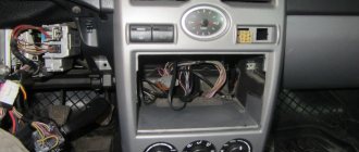
Photo of the block location:
About the ECU and its location is written in the article “Diagnostics of VAZ 2114”. The following shows the pinout of the OBD2 connector and the assignment of contacts of the electronic control units that were installed on the Fourteenth VAZ models.
Connector type No. 1—16-pin OBD-II connector in the shape of a trapezoid:
Brands and years: some models after 2002 with control systems BOSCH MP7.0 Euro-3, BOSCH M7.9.7, January-7.2, January-7.3.
Connector type No. 2 - 12-pin rectangular connector: Make and year: all injection models, except for some models after 2002 that have an OBD-II connector
Deciphering error codes
The first character is a letter and indicates a fault block:
- B - body;
- C - suspension;
- P — engine (ECM, gearbox);
- U - data exchange bus.
The second character is a number, code type:
- 0 — SAE (standard);
- 1.2 - OEM (factory);
- 3 - reserved.
The third character is a number, system:
- 1, 2 - fuel system;
- 3 - ignition system;
- 4 — reduction of exhaust gas toxicity;
- 5 - idle;
- 6 - ECU or its circuits;
- 7, 8 — transmission (automatic transmission).
The fourth and fifth characters are numbers, the error code itself.
OBD1 pinout - 12 PIN (GM12)
Description:
OBD1 (GM12) connector is rectangular in shape, consists of 12 contacts.
Brands and years:
All injection models, except for some models after 2002, which have an OBD-II connector.
Access and location:
Open access. Located next to the ignition switch, partially covered by the steering column cover.
Pinout:
| M | L | K | J | H | G |
| A | B | C | D | E | F |
| Key * | |||||
* Connector Keying - A design element of a removable connector that ensures the correct orientation of the plug and socket.
Example in the photo:
Conclusions and their purpose:
| Conclusion | Color | Purpose |
| A | Weight | |
| B | L-line diagnostics (not always routed) | |
| D | CO potentiometer (not always diluted) | |
| G | Fuel pump control | |
| H | Power supply +12V (not always wired) | |
| M | K-line diagnostics |
OBD2 pinout - 16 PIN
Description:
The OBD2 connector is trapezoidal and consists of 16 pins.
Brands and years:
Gasoline passenger cars and light commercial vehicles manufactured or imported into the United States since 1996 (US CARB and EPA legislation) and in Europe (EOBD) since 2000-2001 (European Union Directive 98/69EG) and Asia (mainly since 1998). ).
Access and location:
Pinout:
| 1 | 2 | 3 | 4 | 5 | 6 | 7 | 8 |
| 9 | 10 | 11 | 12 | 13 | 14 | 15 | 16 |
| Smaller side of trapezoid | |||||||
Example in the photo:
Conclusions and their purpose:
| № | Color | Purpose |
| 2 | J1850 Bus + | |
| 4 | Body grounding | |
| 5 | Signal Ground | |
| 6 | Line CAN-High, J-2284 | |
| 7 | K-line diagnostics (ISO 9141-2 and ISO/DIS 14230-4) | |
| 10 | J1850 Bus- | |
| 14 | Line CAN-Low, J-2284 | |
| 15 | L-line diagnostics (ISO 9141-2 and ISO/DIS 14230-4) | |
| 16 | Power supply +12V from battery |
Diagnostic connector pins for used protocols
Pins 4, 5, 7, 15, 16 - ISO 9141-2.
Pins 2, 4, 5, 10, 16 - J1850 PWM.
Pins 2, 4, 5, 16 (without 10) - J1850 VPW.
The ISO 9141-2 protocol is identified by the presence of pin 7 and the absence of pins 2 and/or 10 on the diagnostic connector.
If pin 7 is missing, the system uses the SAE J1850 VPW (Variable Pulse Width Modulation) or SAE J1850 PWM (Pulse Width Modulation) protocol.
All three data exchange protocols operate via a standard OBD-II J1962 connector cable.
The correct connection diagram for a 12 PIN block with a 16 PIN adapter
Autocom Cable Sets
There are universal kits on sale, for example, a set of Autocom CDP+ Trucks diagnostic cables - used to connect the Autocom CDP+ scanner to trucks with old-style diagnostic connectors.
List of cables included in the kit:
- Diagnostic cable Autocom - Knorr, Wabco Trailer 7 pin
- Diagnostic cable Autocom - MAN 12 pin
- Diagnostic cable Autocom - MAN 37 pin
- Diagnostic cable Autocom - IVECO 30 pin
- Diagnostic cable Autocom - SCANIA 16 pin
- Diagnostic cable Autocom - Mercedes-BENZ 14 pin
- Diagnostic cable Autocom - Renault 12 pin
- Diagnostic cable Autocom - VOLVO 8 pin
With the TRUCKS software package, you are able to perform brand-specific diagnostics for light and heavy commercial vehicles, buses and trailers since 1995. A total of 37 different brands.