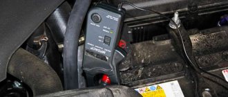
For effective business use of Gazelle cars, all engine systems must work properly. One of the key elements that ensures efficiency and maximum engine performance is the mass air flow sensor. This device is known to motorists under the abbreviation DMRV, or in the English version MAF. A malfunction or incorrect operation of this sensor will in any case lead to additional costs: increased fuel consumption or the purchase of a new mass air flow sensor for your Gazelle car. Therefore, the driver must ensure conditions under which the flow meter will last as long as possible.
Checking the regulator for functionality
Diagnostics of the flow meter is carried out using a voltmeter:
- First disconnect the battery. Use a screwdriver to pry up the spring clamp of the block, and then disconnect the flow meter plug.
- Use a screwdriver to loosen the clamps and remove them.
- Remove the controller, then install pieces of polyvinyl chloride tube onto the contacts of its connector.
- Install the ends of the wires into these sections, as shown in the diagram, approximately 7-8 mm. When connecting, you should be guided by the profile of the end of the plug.
- Now you need to take the tester readings with the device switch turned off. If the controller is working properly, then the voltage level on its pins 2 and 3 should be about 1.3-1.4 volts.
- Then the switch should be turned on for a short time, while the tester readings are checked again. If the device is working properly, then the voltage value at its contacts should increase to 8 volts or around that. At the same time, you will notice that the sensitive element on the device (if it is a thread) has warmed up to red. If the diagnostics showed different values, then the flow meter must be replaced. The assembly procedure is carried out in reverse order.
Photo gallery “We check the mass air flow sensor ourselves”
1. Connection diagram for mass air flow sensor for diagnostics
2. Electrical diagram for connecting the mass air flow sensor
3. Diagnostics of the flow meter with a voltmeter
Where is it located and what is it used for?
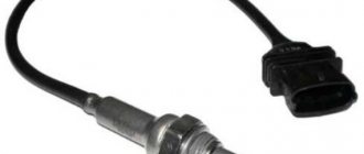
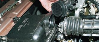
This is a small car part that will be difficult for inexperienced car enthusiasts to find. We open the hood of the car and move our eyes from the air filter to the engine. It is located in front of the intake manifold; you will see a plastic insert in the gap in the air duct with wires.
It is not by chance that he is in this place. It measures the amount of air sucked in by the engine so that the electronic control unit can properly prepare the air-fuel mixture. If the mass amount of air is small, then less fuel needs to be supplied and vice versa. Otherwise, the mixture will be lean or rich. Which will lead to unstable operation of the power unit.
Fuel temperature sensor
A malfunction is usually indicated by a warning lamp on the dashboard with the inscription “Check engine”. Temperature sensor:
- Since 1995, some VAZ 2107 injection models have included a fuel heating temperature controller.
- It is designed to control the heating of the fuel inside the gas tank, and is a thermistor.
- The thermistor resistance changes in inverse proportion to the heating of the fuel in the tank.
- The thermistor is attached to a sensor assembly that controls fuel consumption, which is placed inside the tank.
Note: The information coming from the thermistor is used by the PCM for diagnostic purposes. Failure of the sensor leads to the recording of a corresponding malfunction code in the OBD system memory. Performing the procedure described below will result in a fault code being stored in the OBD permanent memory, which will be illuminated by the “Check Engine” warning lamp on the instrument panel. Once you have completed the check and related repairs, clear the system memory.
- Remove the rear seat, then the cover that gives access to the fuel pump and fuel flow/temperature sensor assembly. We check the correctness of the power supply to the fuel heating controller. Disconnect the electrical wiring from the pump assembly and fuel flow/temperature sensor.
- We connect the positive probe of the voltmeter to the pink-blue wire of the connector, and the negative probe to the black wire.
- Turn on the ignition, the device reading should be 5.0 Volts.
- Otherwise, we check the condition of the electrical wiring between the sensor and its PCM/ground. If everything is in order with the wiring, we take the car to a service station to diagnose the control module and carry out restoration repairs.
- Using an ohmmeter, measure the resistance between the terminals of the fuel flow/temperature sensor.
- The sensor resistance at temperature (20 C) should be about 2300 ÷ 2700 Ohm. The most accurate check of the functioning of the sensor is carried out by removing it from the car and lowering it into a vessel of water heated over a fire.
- We compare the measurement results in accordance with the resistance change map.
- We replace the faulty controller.
Replacing the air flow sensor
To replace the sensor with your own hands, you need to prepare a shaped screwdriver and a “10” key.
The replacement procedure consists of the following steps:
- First you need to turn off the ignition and open the hood.
- Then you need to disconnect the negative terminal on the battery.
- At the next stage, you need to loosen the clamp with which the corrugation is attached to the mass air flow sensor.
- Next, remove the corrugation from the pipe.
- Then you need to bend the comb and disconnect the sensor connector.
Then, using a key set to “10”, you need to unscrew the sensor mounting bolts to the air filter housing. Now you can remove the mass air flow sensor. Installing the sensor yourself is carried out in the reverse order.
Thus, if the car stalls and has all the signs of a breakdown of the mass air flow sensor, then before you start repairing it, you should check the level of its signal, it should not be low, perform a full diagnosis of the car and repair all faulty components and parts.
Briefly about the renovation
As a rule, MAF sensors that have become unusable cannot be repaired, except in cases where they require washing and cleaning.
In some cases, it is possible to repair the volumetric air flow sensor board, but this process will not prolong the life of the device for long. As for the boards in film sensors, without special equipment (for example, a programmer for a microcontroller), as well as skills and experience, it is pointless to try to restore them.
Internal combustion engines in cars operate by supplying not only gasoline alone, but a combustible fuel mixture into the combustion chamber. The concept of fuel mixture refers to a certain amount of gasoline and air. If on the predecessors of the UAZ Patriot SUVs, air supply adjustment was the responsibility of the driver, now a special sensor known as the mass air flow sensor is responsible for this. The mass air flow sensor determines the required amount of air that is required to be supplied to the cylinders along with fuel. Thus, a malfunction of this device leads to improper operation of the engine, so you need to know how to troubleshoot the product, as well as troubleshoot and replace the product on a UAZ Patriot SUV.
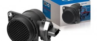
The mass air flow sensor on the UAZ Patriot SUV is a plastic pipe, the functioning of which is carried out by changing the value of internal resistance. Power is supplied to the sensor via wires. The product is located under the hood of the car after the air intake filter on the intake manifold between the air filter and the exhaust pipe. The photo below shows the location of the product.
UAZ Patriot SUVs are equipped with two types of mass air flow sensors type HFM5-4.7 with number 0280218037 from Bosch or mass air flow sensor from Siemens type 20.3855. The main purpose of the sensor is to determine the volume of air that passes through it. But, in addition, the mass air flow sensor allows you to determine the temperature of the incoming air, as a result of which the controller calculates the exact volume of air required to create the air-fuel mixture. The temperature of the incoming air is controlled by means of a sensor installed in
thermister. In the event of a product failure, the controller receiving the signals takes a fixed air temperature value of 33 degrees. The cost of the product is about 3000-5000 rubles, which depends on the manufacturer of the product. Let's look at the main types of malfunctions of the mass flow sensor on the UAZ Patriot SUV.
Types of faults
A faulty mass air flow sensor leads to disappointing consequences, so it is very important to ensure its performance. Malfunctions of these devices may manifest themselves in the following ways:. What does the sensor consist of?
What does the sensor consist of?
- The first factor indicating a malfunction of any element on the car is the illumination of the Check Engine indicator.
- At the same time, an increase in fuel consumption is observed.
- The UAZ Patriot car cannot be started after the engine has warmed up.
- While the car is moving, the driver can feel the UAZ Patriot “stupid”.
If the above symptoms are detected, you should immediately proceed to correct the breakdown. To do this, the first step is to remove the mass air flow sensor and inspect it. Let's look at what the process of removing the mass air flow sensor on a UAZ Patriot Euro-3 SUV is like.
Removal and replacement
The process of removing the product is not difficult and does not take more than 10-15 minutes. All you need to remove the sensor is a 10mm wrench and a Phillips screwdriver. The first step is to de-energize the car by removing the negative terminal from the battery. After this, we proceed to the direct process of removing the sensor from the UAZ Patriot SUV:
Disconnect the hoses from the sensor
- From the bottom of the device, you need to press the plastic clamp of the terminal block and remove it from the sensor.
- Next, loosen the clamps using a Phillips screwdriver.
- Now you can remove the rubber pipes from the product and remove the released element.
This is actually the mass air flow sensor of the UAZ Patriot SUV Euro-3 and Euro-4. After removal, you can check its serviceability. How the mass air flow sensor is checked is discussed below. If this device becomes unusable, it must be replaced with a new part. The process of installing the mass air flow sensor on a UAZ Patriot SUV is performed in the reverse order of removal.
Overview of sensors of the electronic engine control system ZMZ-406
Crankshaft position sensor ZMZ-406
The inductive sensor ZMZ-406 (0 261 210113 or 406.3847113) for GAZ-3110 Volga, Gazelle-3302 cars is designed to determine the angular position of the crankshaft, synchronize the operation of the control unit with the engine operating process and determine its rotation speed.
The sensor is installed in the front of the ZMZ-406 engine on the right side. The sensor structure is shown in Fig. 33.
Fig.33. Crankshaft position sensor for GAZ-3110 Volga, Gazelle-3302 cars
1 - sensor winding; 2 - body; 3 - magnet; 4 - seal; 5 - wire; 6 — mounting bracket; 7 - magnetic circuit; 8 - sync disk
The sensor is an inductive coil 1 with a magnet 3 and a core 7. The sensor works in conjunction with a toothed synchronization disk 8 mounted on the crankshaft pulley.
The passage of the teeth of the synchronization disk 8 past the end of the sensor core 7 causes a change in the magnetic flux in the sensor. A change in magnetic flux causes an alternating electric current to appear in the sensor coil.
The resulting alternating voltage is transmitted to the control unit, which processes them with other sensor signals and generates the parameters of electrical pulses for the operation of injectors and ignition coils.
If the crankshaft position sensor of the internal combustion engine ZMZ-406 of the GAZ-3110 Volga, Gazelle-3302 or its circuits fails, the operation of the ignition system and, accordingly, the engine stops.
The serviceability of the sensor can be checked with an ohmmeter. The resistance of the sensor coil should be in the range of 850-900 Ohms. Normal operation of the sensor is ensured when the gap between the sensor core and the teeth of the synchronization disk is within 1+0.5 mm.
A better check of the sensor's serviceability should be carried out using the DST-2 device when cranking the engine with the starter.
Camshaft position sensor ZMZ-406
The internal combustion engine sensor ZMZ-406 camshaft position 0232103006 or 406.3847050 for GAZ-3110 Volga, Gazelle-3302 cars (phases) is designed to determine the top dead center of the piston of the first cylinder during the compression stroke.
The sensor is installed on the left side of the cylinder head (at the fourth cylinder).
The sensor is an electronic device that operates on the Hall effect. When a metal plate mounted on the camshaft passes past the end of the sensor, the magnetic flux of the sensor changes.
This causes an electrical signal to appear in the sensor, which is amplified and transmitted to the control unit.
Signals from the ZMZ-406 engine sensors of the GAZ-3110 Volga, Gazelle-3302 camshaft position and crankshaft position sensors, processed in the control unit, make it possible to synchronize the fuel supply by injectors to each engine cylinder (only during the compression stroke).
Fig.34. Electrical circuit for checking the camshaft position sensor ZMZ-406 for GAZ-3110 Volga, Gazelle-3302 cars
1 - sensor; 2 — sensor plug; 3 - resistance 0.5-0.6 kOhm; 4 - battery; 5 — LED AL307; 6 - metal plate
If the camshaft position sensor or its circuits fail, the control unit turns on the warning lamp and switches to backup mode with fuel supplied to all engine cylinders simultaneously.
The serviceability of the camshaft position sensor can be checked by assembling the circuit shown in Fig. 34. Moving the metal plate 6 past the end of the sensor should cause the LED to glow.
A better check of the sensor's serviceability can be carried out using the DST-2 device with the engine running.
Mass air flow sensor ZMZ-406
The sensor (flow meter) of the engine of the GAZ-3110 Volga, Gazelle-3302 mass air flow 0280 212 014 or IVKSH407282000 hot-wire type is designed to determine the amount of air used to fill the cylinders during engine operation.
The sensor is installed in the intake system, after the air filter.
Fig.35. Mass air flow sensor ZMZ-406
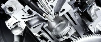
1 - ring; 2 - platinum thread; 3 - temperature compensation resistance; 4 — bracket for fastening the ring; 5 — electronic module housing; 6 — safety net; 7 - retaining ring; 8 — sensor housing; 9 — CO adjustment screw; 10 - cover; 11 — electrical connector block; 12 - plug; 13 - seal; 14 - electronic module
The sensor structure is shown in Fig. 35. In the housing 8 there is a ring 1, inside which there are a sensitive element 2 in the form of a platinum thread with a diameter of 0.07-0.10 mm and a temperature compensation resistor 3, included in the bridge circuit of the electronic module 14, the sensor.
The electronic circuit of module 14 maintains the temperature of the platinum filament at about 150°C. During engine operation, air drawn into the engine cylinders passes through housing 8 and ring 1, cooling the platinum filament.
The electrical power expended to maintain the filament temperature at the same level is a parameter for determining the amount of air passing through the sensor.
Since the temperature of the platinum filament also depends on the temperature of the passing air, temperature compensation resistor 3 (determining the temperature of the passing air) makes an appropriate correction to the operating mode of the electronic module.
Signals from the ZMZ-406 sensor of GAZ-3110 Volga, Gazelle-3302 cars enter the control unit, are processed and used to determine the optimal duration of electrical pulses for opening the injectors (the required amount of fuel for a given amount of air is determined).
To avoid contamination of the platinum filament, the electronic module provides for a short-term supply of increased voltage to it for heating up to 100 CGS.
When the temperature of the filament rises, all contaminants that fall on it burn out (burning mode).
The electronic module has a variable resistor with which you can adjust (screw 9) the concentration of carbon monoxide in the exhaust gases when the engine is idling.
If a malfunction occurs in the ZMZ-406 sensor of the GAZ-3110 Volga, Gazelle-3302 vehicles or its circuits, the control unit switches to a backup mode of operation according to the data stored in the unit’s memory.
The control unit signals the driver about a malfunction of the mass air flow sensor by turning on the warning lamp.
Fig.36. Electrical circuit for checking the ZMZ-406 sensor for GAZ-3110 Volga, Gazelle-3302 mass air flow vehicles
1 — sensor plug connector; 2 - switch; 3 - battery; 4 - voltmeter
The serviceability of the sensor can be checked by assembling the circuit shown in Fig. 36. When connecting the source, voltmeter 5 should show 1.3-1.4 V, and when switch 3 is turned on briefly, voltmeter 5 should show approximately 8 V. Platinum thread 2 (Fig. 3) should heat up to red.
What you need to know about the device to connect wires
dialing mode
If you plan to test the wiring in your apartment, you need to know several fundamentally important facts about multimeters. First of all, it is worth noting that you can check the wire with the simplest device. An inexpensive Chinese model with minimal capabilities is quite suitable.
But at the same time, it is most convenient to use a device that has the dialing function itself. In order to set the device handle to the appropriate position, you need to turn it in the direction of the diode icon (as an option, an image of a sound wave can additionally be applied). This means that when checking the integrity of the wire, a sound signal will sound when the contacts are closed.
But the presence of sound is completely optional for testing wires with a multimeter. The fact that the circuit is broken will be indicated by a unit on the display, indicating that the resistance level between the probes is higher than the measurement limit. If there is no damage in the area under study, the resistance value will be displayed on the screen, which ideally should tend to zero (subject to operation in short-distance household networks).
DMRV setup ZMZ 406
ToxaVolgovod » 12 Oct 2010 00:38
I keep tormenting my Volga, it doesn’t give in to me, it’s overflowing with something. brain Mikas 5.4 wires seemed to be ringing on the sensors, everything seemed to be in order, the sensors changed everything from a working donor who then, upon their return, left perfectly, but there was a Mikas 7.1 and just the same air sensor film and I have a thread. Well, today I moved it, knocked it, it seemed like it started to depict something... at the beginning I had it so that the thread inside was constantly red, as I understand it, the burning mode was stuck. then I tapped it and this effect seemed to disappear... there you go. but the car was working so that the engine was about to fly out from under the hood and danced anyway. When I press the gas pedal the engine stalls. Therefore, it’s a rich mixture or a poor mixture... I assume it’s rich because it stinks very much and throws away the candles.
In general, the question is what. There is some kind of bolt on the edge of this sensor.
Another question is that maybe it shows error 53, but the sensor is working and the wiring also seems to be normal. ?
ToxaVolgovod » 12 Oct 2010 01:09
serg52 » 12 Oct 2010 06:45
-Keeper- » 12 Oct 2010 08:44
fil m848kv-52 » 12 Oct 2010 08:49
In a flea market (film) Siemens MAF
YES YES! You screwed up the potentiometer adjustment 100 pounds and it’s screwed up! They adjust it and look at the computer (rich or lean mixture) CO adjustment! You don’t even care! Don’t go there yourself if you don’t know!
Volga is a small apartment
ToxaVolgovod » 12 Oct 2010 15:18
The fact of the matter is that I remembered the position that it was and decided to twist it at a speed and turn around with the car running. I twisted it, nothing changed at all, then I returned it to its previous state.. but you don’t know about it, don’t bother.. I’m not one of those people, I’m interested in how everything works. And I’m not used to giving money to diagnostics and services..
and by the way, fil m848kv-52 your link is mediocre because I don’t have film, but thread. and there is another connection.
ToxaVolgovod » 12 Oct 2010 15:21
ace_rus » 12 Oct 2010 15:29
ToxaVolgovod » 12 Oct 2010 19:49
Purpose of the MAF sensor
In electronic ignition systems, the ratio of fuel and air in the fuel mixture injected into the internal combustion engine cylinders is set by the on-board computer. Therefore, a mass air flow sensor is necessary to adjust these parameters at each individual moment in engine operation.
Rice. 2 Purpose of a VU meter in the electronic ignition system of an injection engine
Otherwise, either a lean or rich mixture will enter the combustion chambers, which will lead to increased fuel consumption, engine overheating, and intense wear of friction parts. The power will decrease, the characteristics of the internal combustion engine will be disrupted, and the engine will stall.
Installation location
To save fuel, modern cars are equipped with injection engines with electronic ignition. In a simplified form, an injector is a point injection of a mixture through a nozzle into a cylinder or intake tract. The ECU control unit is usually called the “brains” of the car; it is this body that adjusts the four main parameters of the electronic control system (ECM):
- injection frequency;
- injection moment;
- fuel mixture dose;
- the ratio of fuel and air in it.
To obtain this data, the principle of remote sensors is used. For example, the moment of injection is determined by the readings of the crankshaft sensor DPKV, and the mass air flow sensor is responsible for the proportions of the mixture. All air entering the car engine passes through the throttle valve, which is located between the intake manifold and the air filter.
Rice. 3 VU meter location
Therefore, it is most logical to look for the mass air flow sensor directly in front of the throttle valve, where it is located.
Attention: Information is transmitted to the controller from seven sensors: camshaft DRV, detonation DD, lambda probe, throttle valve DPZ, cooling system DTOZh, volume meter DPKV and crankshaft DPKV.
Based on these signals, the ignition module is turned off, the fuel pump and injectors, the fan and the idle regulator are turned on.
Design of the mass air flow sensor
Car enthusiasts call the mass air flow sensor a flow meter; in specialized literature it is designated as a volume meter. What is actually measured inside this electronic device is not the volume of air passing through it, but its mass per unit of time, moreover, compressed.
Since Ohm's law is familiar to every school graduate, the design of the mass air flow sensor is understandable to 100% of car enthusiasts:
- the device is analogous to an anemometer that measures flow speed;
- inside a tubular housing with an air deflector and a mesh metal screen at the inlet, the sensor itself is inserted perpendicular to the flow with a connector extending outward;
- Apply a current of 500 - 1200 µA to the thread or film inside the sensor, remove the voltage value 0 - 1 V in reverse flow or 1 - 5 V in normal mode;
- when current passes, the element heats up, its resistance increases (500 - 700 Ohms), and the voltage changes accordingly;
- The air flow cools the wire, the resistance decreases, and the voltage increases.
Rice.
4 Design of a filament air flow sensor The air flow sensor is connected according to the diagram below:
- green – to ground;
- white-gray – output voltage;
- yellow – input signal;
- dark – output signal.
Rice.
5 Connection diagram for the mass air flow sensor. A platinum resistor on a ceramic plate is built into the film mass air flow sensor. In a filament sensor, the resistance is made of an alloy of iridium and platinum. The first VAZ models were equipped with sensors that controlled the flow rate based on the frequency of the output signal. Currently, domestic and foreign cars have mass flow sensors that determine fuel consumption based on voltage.
To increase functionality, the operating sensor uses two temperature-dependent elements.
Since the difference in air temperature can introduce an error into the device readings, the second thread element compensates for it by measuring the temperature of the environment.
Common to all devices is the presence of an adjusting screw, which is used to adjust the CO with your own hands. The designs of different manufacturers differ in the following details:
- thread thickness – 0.07 – 1 mm;
- method of fastening the thermally dependent element - laser welding, hooking with a loop on an elastic suspension;
- thread geometry – V-shaped or U-shaped;
- The design of the stand is square, eliminating errors when rotating the element around its axis.
Rice.
7 German sensor and Russian analogue In addition to these differences, the following factors should be taken into account:
- thread devices began to be produced by Bosch and General Motors, then interchangeable analogues appeared from the APZ and JSCB Impuls plants;
- introduced a film-based air flow sensor from Siemens, which was copied by the Kaluga Research and Production Enterprise AVTEL;
- the thread is heated to 140 - 170 degrees, the film to 100 degrees;
- the accuracy of measuring film modifications is lower - 4%, for thread modifications is higher - 1%;
- The devices are interchangeable with each other, but only together with a bundle of wires, since the pinout of the wires does not match.
Currently, thread sensors are discontinued in Europe for a number of reasons:
- low level of manufacturability of thread production;
- the presence of corrective lambda probes;
- automatic calibration of films in blowing units.
In other words, manufacturers sacrificed speed and high accuracy for the sake of significantly reducing the cost of film mass air flow sensors.
Attention: For film sensors, the connection diagram to the MIKAS-7.1 controller, version 241.3763-31, is adopted. Filament air flow sensors MIKAS-5.4 and MIKAS-7.1 (version 241.3763-01) are used.
There is a domestically produced mass air flow sensor M with protection against overvoltage, short circuit and conducted interference.
Rice. 9 Modification of mass air flow sensor M
By default, thread sensors are based on the principle of self-cleaning of a temperature-dependent element. After stopping the engine, the ECU independently supplies current to the filament to warm it up to 1000 degrees for 1 second. The adhering dirt burns out completely.
Basic faults
There is practically nothing to break in a film sensor, so they are considered “eternal”. The spiral of filament air flow sensors is less reliable, however, these electronic devices cannot be repaired in principle, with the exception of cleaning and replacement. The following symptoms will help determine the malfunction of this particular sensor:
- spontaneous decrease in engine power;
- decreased acceleration dynamics;
- engine not ;
- increase in fuel consumption unjustified by driving style;
- illuminated Check errors;
- change in XX speed in any direction, appearance of jerks;
- The car stalls when changing gears.
When diagnosing a low signal level, the following options are possible:
- the plug fell off;
- the power supply is broken;
- oxidation or loss of mass;
- signal wire break.
Rice.
10 Mechanical damage to the VU meter Since the electrical device is not repairable, but has a simple design, diagnostics can be performed on your own according to the principle of increasing its complexity.
Diagnostics of mass air flow sensor
In principle, the mass air flow sensor is not as critical for starting the engine as, for example, the DPKV. It can be turned off by pulling out the connector, the ECU will go into emergency mode and will determine portions of air in the fuel mixture using another sensor - the TPS throttle position.
Therefore, the breakdown is determined in several stages according to the degree of complexity:
- visual inspection and disconnection of the sensor;
- determining the compliance of a specific modification of the mass flow sensor with the ECU firmware;
- diagnostics with a tester in voltmeter mode.
This will reduce the complexity of the process. For example, before checking the mass air flow sensor with a tester, you should make sure that the sensor is compatible with a specific MIKAS controller and that the original brains have not been flashed.
Sequence of actions when calling
- Before you test the circuit with a multimeter, you need to turn the handle of the device to the desired position.
- Install the ends (measuring leads) into the appropriate sockets. The black wire goes into the socket marked COM (sometimes it can be marked with “*” or a ground sign), and the red wire goes into the socket where the Ω sign is indicated (sometimes it can be marked with an R sign). It is worth noting that the Ω sign can be applied either separately or in combination with the designations of other units of measurement (V, mA). This is the correct position of the test leads, which will allow you to maintain polarity when making further measurements. Although if only the integrity of the wires is checked, their relative position will not affect the result obtained.
- Turn on the device. A separate button may be provided for this, or activation may occur automatically when the knob is turned to the desired position when selecting measurement limits or operating modes.
- Connect the measuring ends to each other. If a signal sounds, it means that the device is operational and ready for use.
- Take the cable or wire being tested (its ends must first be stripped of insulation, stripped to a metallic shine, and dirt and oxides removed from the surface). Touch the test leads to the exposed areas of the conductor.
- In case of continuity, a signal will sound, and the device readings will either be 0 or indicate the resistance value. If the display shows 1 and there is no beep, the tested conductor is broken.
https://youtube.com/watch?v=EIyKzTBhyBA
https://youtube.com/watch?v=EIyKzTBhyBA
Rules for safe calling using a multimeter
testing the network cable with a multimeter
Working with electricity does not allow for unprofessionalism, so a certain list of rules has been developed that make it possible to make it as accurate, fast and safe as possible.
When making calls, it is most convenient to use special tips at the ends of the measuring wires, which are more commonly known as “crocodiles”. They will make the contact stable and free your hands when taking measurements. When testing, the circuit being tested must always be de-energized (even low-current batteries must be removed). If there are capacitors in the circuit, they must be discharged by short-circuiting
Otherwise, the device will simply burn out during work. Before checking the integrity of a long length of conductor when taking measurements, it is important not to touch its bare ends with your hands. This is due to the fact that the resulting readings may be incorrect.
When testing a multi-core cable, it is necessary to separate and strip all existing cores from both ends. After this, you need to check the circuit for the presence of short circuits in it: to do this, a “crocodile” is attached to each core in turn, and all the remaining ones are touched with the other measuring end in all possible combinations.
Check to see if there is a short circuit between the cable cores. If the indicator shows “1” and there is no sound signal, then everything is in order, otherwise there is a short circuit.
In this case, a sound signal will indicate the presence of a short circuit between the tested conductors
This may not be of practical importance for small cross-section multi-core cables operating in low-current networks, but when working with high voltages it is fundamentally important
We call the cable cores. There is a sound signal - everything is fine, otherwise the core is damaged.
To determine the integrity of the cores, the same operation is performed, only at one end of the cable all stripped cores are twisted together
When searching for a break, it is important to consider that the absence of a sound signal at either end will indicate a violation of the integrity of the conductor
How to check the serviceability of the mass air flow sensor
First of all, you need to regularly carry out computer diagnostics of your car, even in a garage, using basic car scanners. Any version of the Gazelle car is equipped with an OBD-II port, with which you can obtain detailed information about the operation of the engine’s electronic systems.
The initial parameters of the air flow sensor (we first select the model and type of engine on your car) are programmed into the diagnostic program. So a deviation from the norm will be recorded, and advanced programs will also suggest the probable cause of the breakdown.
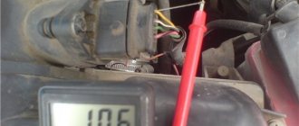
However, there is a more primitive method that you can use if you don’t have a diagnostic scanner at hand. Every car enthusiast has a digital multimeter in their garage. The main thing is that its error is low: the voltage readings at the information contact of the mass air flow sensor vary within hundredths of a volt, and it is precisely this minimum range of values that the ECU is designed for.
The illustration shows the pinout of a sensor from Siemens, or its Russian analogues Avtel and Elkar.
- First of all, we check the integrity of the wiring harness and cable contact group. To do this (having first disconnected the negative terminal of the battery), disconnect the connector and connect the battery back. Turn on the ignition without turning the starter. There should be 12 volts on pin #2. Not 13.5, as on the battery, but precisely 12, after the voltage regulator. At pin No. 4 the sensor is supplied with 5 volts.
- Then we connect the connector back (remembering to temporarily disconnect the battery ground). We check the most important sensor signal: thermistor compensation voltage. With the ignition on, this value should be in the range of 0.99 - 1.02 volts. 1.03 - 1.05 volts are allowed, but such a mass air flow sensor will not last long. Any other value, even with a tolerance of 0.01 volts from the nominal value, indicates a breakdown.
Measure the voltage
If you have a multimeter at hand, measure the voltage at the output . With the ignition off: push the needle under the yellow wire into the rubber seal. With the ignition on, but not with the engine running: you measure the voltage between the needle and ground - if it is more than 1.1 (Chinese multimeters almost always lie, mine has a documented error of 0.5%), then the mass air flow sensor is definitely dead. They say that carefully cleaning the air flow sensor with a carb cleaner can revive it, but I have a hard time believing it. But this is only a superficial check.
Now in a little more detail... If we are dealing with a Bosch mass air flow sensor, then first picking up the multimeter you need to turn the tester into the DC voltage measurement mode (we set the measurement limit to 2V). To understand the contacts, here is the pinout:
- Yellow (closest to the windshield) - mass air flow sensor signal input;
- Gray-white—sensor supply voltage output;
- Green — sensor grounding output;
- Pink-black - to the main relay.
Changes in colors are of course possible, but the location should not change.
The process for checking the flow meter is as follows:
- Without starting the engine, turn on the ignition. Connect the tester with the red end to the yellow MAF wiring, and the black probe to the green (that is, to ground).
- The voltage at the output of the new sensor is about 0.996-1.01 V. As the sensor wears out, it gradually changes and, as a rule, increases, and accordingly, the higher this value, the greater the wear of the mass air flow sensor.
The voltage picture looks like this:
- 1.01-1.02 - good condition of the sensor;
- 1.02-1.03 - not bad condition;
- 1.03-1.04 - the life of the mass air flow sensor is ending;
- 1.04-1.05 - near-death state, if there are no negative symptoms, then it can be used further;
- 1.05 and above - it’s time to change the mass air flow sensor.
A 100% result can be obtained by checking with special equipment. By the way, the same readings can be obtained without a tester, using the on-board computer (group of parameters “voltage from sensors”, Udmrv).
You should also remember and pay attention to some symptoms that indicate a malfunctioning mass air flow sensor even without such checks, the main ones are:
- An error appears on the display (Check Engine);
- Fuel consumption increases;
- It doesn't start well when hot;
- Acceleration dynamics will noticeably decrease (the car will accelerate slowly);
- There is a loss of engine power.
Possible controller malfunctions
The following errors may indicate device malfunctions:
- P0131, P0132. These errors indicate that the signal level from the oxygen sensor is too low or too high.
- P0134. The control unit did not detect the activity of the lambda probe.
- P0135. This error may indicate an open circuit connecting the sensor, as well as a possible short to power or ground.
- P0133. Controller response is too slow.
- P0137, P0138. Very low or high signal from the second lambda probe.
- P0141. The malfunction also concerns the second oxygen sensor, in this case we are talking about an open circuit or short circuit (the author of the video is the Lty D channel).
Description of the oxygen sensor
A lambda probe or oxygen sensor is mounted in the Gazelle exhaust system. This device is used to measure the volume of oxygen in exhaust gases. By design, the device is equipped with a built-in heating element, which allows you to quickly warm up the controller to ensure its normal operation. The readings taken by the lambda probe are used to adjust the fuel supply, check the condition of the engine, as well as the exhaust gas neutralization system.
Tags: dmrv 3110 thread
Comments 8
no green red some yellow with black stripes
There is a 6 pin DMRV pinout, my wires are completely different colors
They wanted to cheat you out of money in the service department! I don't visit them anymore. You can calcinate the thread yourself by briefly applying 12 volts to the 4th leg, but there is no particular point in this. When the ignition is turned off, the ECU itself burns the thread for cleaning. If the sensor is working and the air flow rate is normal 12-13 kg, then there is no point in tinkering with it - there is no need to interfere with its work, and if it already shows the weather on Mars, then there will be no point in burning it, most likely the sensor will need to be replaced. I consider it barbaric to water the mass air flow sensor with all sorts of crap like slurry to clean the carburetor. There is also electronic filling, or, in extreme cases, pure alcohol. Can you imagine what kind of deposits after this slurry will be on the thread when the burning is completed?
It seems to me that it is useless to clean it; it’s easier to buy a new one
You supply 12 volts to some contact and you can clean it manually) but is there any point? When you turn off the ignition, the thread from the signal from the block itself heats up) so they wanted to trick you)
According to swarm of information, there is a simple diagram of how and what to connect it to so that all the crap goes away from it!
I DON’T BELIEVE IN THIS SHIT. YOU’LL ONLY THROW OUT YOUR MONEY AND STILL GO FOR A NEW ONE. WHEN I CAME OUT, I BUYED A NEW ONE.
probably in order to stupidly rip off the money, and this is the most favorite activity in the service))
source
Possible controller malfunctions and ways to eliminate them
Several malfunctions may occur in the operation of the device:
- The sensitive element of the sensor - film or thread - is damaged. Typically, this problem occurs due to wear and tear. It is theoretically possible to repair such a regulator, but in reality it can take a lot of time and effort. Therefore, many car enthusiasts simply change the mass air flow sensor.
- The flow meter is clogged. This problem usually occurs as a result of prolonged use of the sensor. Clogging of the device, especially when constantly using the car in city mode, is a completely normal situation. The problem can be resolved by cleaning the flow meter or replacing it.
- Another malfunction is damage to the contacts or their oxidation. Damage can occur as a result of long-term operation of the flowmeter in vibration conditions, and oxidation can be caused by high humidity or long-term operation. In any case, you can try to repair the damage to the plug, but if that doesn’t work, the connector can always be replaced. As for oxidation, this problem can be solved by cleaning the contacts. An iron construction brush or a toothbrush can be used for this.
- Damage to wiring. It’s not exactly a malfunction of the flow meter itself, but if a break occurs in a section of the electrical circuit, the device may stop working. Accordingly, this will also affect the performance of the motor (the author of the video is the Simple Opinion channel).
What symptoms indicate a malfunction of the flow meter:
- an indicator appeared on the dashboard indicating the need to check the engine;
- the car began to consume more fuel;
- at idle speed the engine is unstable, the speed itself constantly fluctuates;
- the car takes more time to gain speed, the dynamics decrease;
- engine power as a whole has become weaker;
- Due to a non-working flow meter, the driver may encounter difficulties starting the engine, in some cases it is not possible to start it at all.
DMRV gazelle: how to check the sensor, pinout of the DMRV Siemens - watch video
For effective business use of cars, all Gazelle engine systems must work as One. One of the key elements ensuring the efficiency and maximum performance of the engine is the mass air flow sensor.
This device is known to motorists by the abbreviation DMRV, or in the English version Malfunction. MAF or incorrect operation of this sensor in any case will lead to additional costs: increased fuel consumption or the purchase of a new mass air flow sensor for your Gazelle car.
Therefore, the driver must provide conditions under which the flow meter will last as long as possible.
Operating principle of air flow sensor
The device is installed between the air filter and the throttle valve. It determines the amount of air passing into the engine intake manifold.
There are two constructive solutions:
- Mechanical (vane type) using a plate of a certain size connected to a variable resistor. Under air pressure, the plate changes, the resistance deflects, and the engine electronic control unit receives information for the correct formation of the fuel mixture.
- An electronic sensor can be used (platinum wire) or film. These are the options depending on the environmental class of the car, Gazelle is used in Business. Let's take a closer look at how it works.
The device is an air duct whose diameter corresponds to the air line of the vehicle's intake system. Inside there is a number of electronic principles.
components of the action “thermo-anemometric”. What does this mean in practice?
The main element of the mass flow sensor is resistance, the element of which depends on temperature. Its value is constantly (in real time) compared with a constant reference resistor, which operates under the same conditions (immediate proximity). Air passes through the temperature-sensitive element, and depending on the intensity of the flow, resistance occurs.
GAZ 31 10, 406.20D › Logbook › Mass air flow sensor
In the fall the air flow sensor died. I worked for almost seven years. I took out an old original sensor from the stash, installed it, tweaked the coefficients through the laptop, and threw this one on the shelf until better times.
The other day I remembered about it and took it out for inspection. It turned out that the thread is intact, which means it is quite possible to repair it, especially 95%, since the fault is typical.
Disassembled. The quality is, of course, poor. It looks like the board was etched by hand.
Here he is, the little brat. As I thought, the transistor flew.
I installed it on the car and adjusted the coefficients. It works, even the hourly consumption has decreased.
The cost of a new sensor starts from 2,000 rubles, the price of this transistor is 20 rubles.
source
Checking the regulator for functionality
Diagnostics of the oxygen sensor is carried out as follows:
- First, the device must be inspected. If visual diagnostics made it possible to identify defects in the device, then most likely it was the damage that caused its failure. If so, then the device changes.
- If the error shows an open circuit, then you need to try to find a break in the wiring or damage to the electrical circuit.
- Disconnect the device from the power connector, perform a visual check of both plugs - the sensor itself and the connection circuit. If there are traces of rust or deposits or oxidation on the connectors, you can try to clean them. If the marks are strong and cannot be cleaned off, or if you damaged the contacts while cleaning, they should be replaced.
- If these steps did not help you identify problems, then you will need a tester to proceed further. Get your multimeter ready, reconnect the sensor, start the engine and warm it up to operating temperature, then turn it off.
- Then the oxygen controller will need to be disconnected from the connector again, after which it will connect to the tester.
- The car engine starts again, now you need to sit in the driver's seat and press the gas to increase the speed. The revolutions should be kept around 2500 per minute.
- Look at the multimeter screen - if the value is close to 0.9 W, this indicates that the lambda probe is in good condition and does not require replacement. If the readings do not rise above 0.8 W, this indicates the need to replace the regulator. Then all you have to do is dismantle it and replace it with a new one.
Loading …
Tags: zmz 406
Comments 26
My consumption at XX is generally 0.9-1) Thanks DBP) But in general, the normal consumption for the mass flow sensor is 1.2. If it is too high, it means that the injectors are not topped up, the injectors open more strongly, and from here the instantaneous flow rate is taken based on the opening time. It's either the injectors or the fuel pump. In general, it would be flashed for 580 at least. In terms of temperature - well, it’s not at work. It should be approximately above 80 for various corrections to cease to apply. For 406, the normal temperature is 87 where RCOD RCOK - suspiciously the same - set it according to the gas analyzer. Leave the correction at -2 if you drive at a good 92m. I drove the 95 at -5
I just measured these parameters at 80. and so the fan on 87 turns on. 580 how to flash? Are there any pitfalls? MAF Siemens 20.3855. you need to look at the markings exactly. RCOD RCOK approximately what should they be? Are they exposed to a hot internal combustion engine?
Only the gas valve at operating temperature will tell you approximately; if it is not there, I recommend setting it to zero.
It's not difficult to flash, do you have an adapter for diagnostics? I can upload the firmware slightly corrected
I know how to flash it, and I corrected the old firmware in the fuel supply mode at start-up. otherwise it flooded from -5 degrees and below.
Then there is no reason to worry at all - feel free to upgrade to 580
My consumption at XX is generally 0.9-1) Thanks DBP) But in general, the normal consumption for the mass flow sensor is 1.2. If it is too high, it means that the injectors are not topped up, the injectors open more strongly, and from here the instantaneous flow rate is taken based on the opening time. It's either the injectors or the fuel pump. In general, it would be flashed for 580 at least. In terms of temperature - well, it’s not at work. It should be approximately above 80 for various corrections to cease to apply. For 406, the normal temperature is 87 where RCOD RCOK - suspiciously the same - set it according to the gas analyzer. Leave the correction at -2 if you drive at a good 92m. I drove the 95 at -5
hi, I accidentally came across your comment. Similar shit is happening to me, but I didn’t find any answers, and your comment seems to be close to me... I have 1.4-1.5 on the xx, but sometimes with the tank filled more than half you can see 1.2-1.3 in traffic jams. There is no traction... the engine you accelerate... you get this feeling when you are driving at lower speeds. And there is no carbon deposits on the spark plugs; on the contrary, they are slightly white. Like when depleted. In the summer I changed the throttle, and the spark plugs eliminated the leaks in the engine for a while so I didn’t feel the weight of the car. Like a feather. And then somehow it started to work again... now I’m thinking about the injectors to clean them individually at the stand. Do you think this will increase the filling of the cylinders or should I look elsewhere? I was in diagnostics, the pump presses normally, the phases are not knocked down, the injectors are not clogged. but for some reason on their computer the hourly consumption shows 1.2 and my onboard one is 1.4-1.5
source
Lessons 406
The electrical equipment of a car with a ZMZ-4062.10 engine can be divided into two groups.
First group
These are devices familiar to us from the old “402” engine: starter, generator, battery, spark plugs, ignition coil, coolant temperature sensors, oil pressure, relays and others. They may be slightly different in design and parameters, but their operating principle is the same and is well known. Even checking spark plugs in a new engine is carried out in exactly the same way as in the old one.
Case one
Winter, frosty morning. You are in a hurry to get to work, confidently get behind the wheel of your Volga, turn on the ignition, and see the warning light come on and go out. Everything is fine. You turn on the starter, but the engine does not start. How so? Yesterday I left the car in working order, the light does not “scream” about a malfunction, and the engine is silent.
Remember.
The self-diagnosis mode does not apply to the high-voltage part of the vehicle's electrical system. Most likely, the engine’s spark plugs are “flooded,” and the control light doesn’t care. But don’t rush to unscrew the spark plugs, clean them and heat them. The “4062.10” engine has a cylinder purging mode, but the manufacturers forgot to inform car owners about this.
The GAZ instructions say that when starting the engine, you should not press the gas pedal. Why not? Yes, because if you press it more than halfway, the cylinder purging mode is activated! Air enters the cylinders, but fuel does not. When you blow the cylinders for 5-10 seconds, the engine will start when you release the gas pedal.
Case two
Summer. In the evening, returning home, you were caught in a warm mushroom rain. We parked the car in the garage and noticed a puddle of water on the front passenger's carpet. Just think! And the old Volga was leaking into the edge of the front window. It's like a birthmark...
And in the morning your brand new Volga starts and stalls, starts and stalls... How do you know that the most important electronic “brain” of your car is located under the glove box and it got under the shower.
Remember.
Any electronics does not like moisture or dampness. She seems to be going crazy, giving inconsistent commands.
We carried out measurements on such a “wet” control unit; it transmitted signals to the engine based on an ambient temperature of -12°C, when it was +20°C outside. So he went deaf from such a weather forecast!
Case three
You have decided to wash your car. We drove it out onto the lawn and washed it without opening the hood. They started it up and found that the engine was “troubling.” How can that be, you didn’t wash it!
Everything is very simple. The Volga often has leaks where the rear part of the hood fits on the rubber seal, and when washing, water gets directly onto the electromagnetic injector of the fourth cylinder.
In all cases of water getting on contacts, connections, devices, it is necessary to dry, ventilate, use modern moisture displacers and, of course, thoroughly eliminate all possible moisture ingress into the electrical system. It is also necessary to skillfully arrange a general wash of the engine and engine compartment. It is better to consult a service station.
And the last thing that owners of the “406” need to know. This engine is demanding on the quality of spark plugs. Avoid buying so-called “imported” ones in markets, in gateways, no matter how tempting the price and packaging may be. If you don’t have the money to buy imported spark plugs from real dealers, it’s better to buy domestic ones. And before installing it on the engine, check everything for operation under pressure at a service station.
Integrated Control System Diagnostic Trouble Codes
| 12 | The initial code for displaying diagnostic information (always the first one). |
| 13 | Low signal level from the air flow sensor |
| 14 | High signal level from the air flow sensor |
| 15 | Low signal level from the absolute pressure sensor |
| 16 | High signal level from the absolute pressure sensor |
| 17 | Low signal level from air temperature sensor |
| 18 | High signal level from the air temperature sensor |
| 21 | Low signal level from coolant temperature sensor |
| 22 | High signal level from the coolant temperature sensor |
| 23 | Low signal level from throttle position sensor |
| 24 | High signal level from the throttle position sensor |
| 25 | Low voltage level in the vehicle's on-board network |
| 26 | High voltage level in the vehicle's on-board network |
| 31 | Low level from the first CO corrector |
| 32 | High level from the first CO corrector |
| 33 | Low signal level from the second CO corrector |
| 34 | High signal level from the second CO corrector |
| 35 | Low signal level from the first LAMDA probe |
| 36 | High signal level from the first LAMDA probe |
| 37 | Low signal level from the second LAMDA probe |
| 38 | High signal level from the second LAMDA probe |
| 41 | Malfunction in the first knock sensor circuit |
| 43 | Recirculation valve feedback signal low |
| 44 | Recirculation valve feedback high |
| 45 | Canister valve feedback signal low |
| 46 | Canister valve feedback signal high |
| 51 | Malfunction of 1 control unit (CU) |
| 52 | Malfunction 2 CU |
| 53 | Synchronization sensor malfunction. |
| 54 | Phase sensor fault |
| 55 | Vehicle speed sensor malfunction |
| 61 | Malfunction 3 CU |
| 62 | Faulty RAM memory |
| 63 | Malfunction of the permanent memory of the control unit |
| 64 | Malfunction when reading the non-volatile memory of the control unit |
| 65 | Malfunction when writing to the non-volatile memory of the control unit |
| 71 | Low engine speed when idling |
| 72 | High engine speed when running |
| 73 | Lean mixture when regulated by the first LAMDA probe |
| 74 | Rich mixture when regulated by the first LAMDA probe |
| 75 | Lean mixture when regulated by the second LAMDA probe |
| 76 | Rich mixture when regulated by the first LAMDA probe |
| 81 | Maximum displacement of the OZ when regulating by detonation in the first cylinder |
| 82 | Maximum displacement of the OZ when regulating by detonation in the second cylinder |
| 83 | Maximum displacement of the OZ when regulating by detonation in the third cylinder |
| 84 | Maximum displacement of the OZ when adjusting for detonation in the fourth cylinder |
| 91 | Malfunction in the ignition control circuit of the 1st cylinder |
| 92 | Malfunction in the ignition control circuit of the 2nd cylinder |
| 93 | Malfunction in the ignition control circuit of the 3rd cylinder |
| 94 | Malfunction in the ignition control circuit of the 4th cylinder |
| 99 | High voltage driver malfunction |
| 131 | Malfunction of the injector of the 1st cylinder (short circuit) |
| 132 | Malfunction of the injector of the 1st cylinder (break) |
| 133 | Malfunction of the injector of the 1st cylinder (short circuit to ground) |
| 134 | Malfunction of the injector of the 2nd cylinder (short circuit) |
| 135 | Malfunction of the injector of the 2nd cylinder (break) |
| 136 | Faulty injector of the 2nd cylinder (short circuit to ground) |
| 137 | Malfunction of the injector of the 3rd cylinder (short circuit) |
| 138 | Malfunction of the injector of the 3rd cylinder (break) |
| 139 | Malfunction of the injector of the 3rd cylinder (short circuit to ground) |
| 141 | Malfunction of the injector of the 4th cylinder (short circuit) |
| 142 | Malfunction of the injector of the 4th cylinder (break) |
| 143 | Faulty injector of the 4th cylinder (short circuit to ground) |
| 161 | Malfunction of winding 1 RDV (short circuit) |
| 162 | Malfunction of winding 1 RDV (break) |
| 163 | Faulty winding 1 RDV (short circuit to ground) |
| 164 | Malfunction of winding 2 RDV (short circuit) |
| 165 | Malfunction of winding 2 RDV (break) |
| 166 | Faulty winding 2 RDV (short circuit to ground) |
| 167 | Malfunction in the control circuit of the fuel pump relay (SC) |
| 168 | Malfunction in the fuel pump relay control circuit (open) |
| 169 | Malfunction in the control circuit of the fuel pump relay (short circuit to ground) |
| 171 | Recirculation valve circuit malfunction (short circuit) |
| 172 | Recirculation valve circuit malfunction (open) |
| 173 | Recirculation valve circuit malfunction (short to ground) |
| 174 | Malfunction in the canister valve circuit (short circuit) |
| 175 | Malfunction in the canister valve circuit (open) |
| 176 | Malfunction in the canister valve circuit (short circuit to ground) |
| 177 | Main relay control circuit malfunction (short circuit) |
| 178 | Main relay control circuit malfunction (open) |
| 189 | Main relay control circuit malfunction (short to ground) |
| 181 | Malfunction lamp circuit malfunction (short circuit) |
| 182 | Malfunction lamp circuit malfunction (open) |
| 183 | Malfunction lamp circuit malfunction (short to ground) |
| 184 | Malfunction in the tachometer circuit (short circuit) |
| 185 | Malfunction in the tachometer circuit (open) |
Symptoms of a faulty air flow sensor
If the mass air flow sensor begins to produce incorrect data, then a failure occurs in the system for preparing the fuel-air mixture, and the proportions of fuel and air are disrupted. This results in the following symptoms of a malfunction:
- Unstable idle speed
- Violation of the smooth running of the car
- Difficulty or impossible to start the engine
- Noticeable deterioration in vehicle dynamics
- Increased fuel consumption
- The yellow "Check Engine" light on the instrument panel does not go out
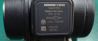
Check engine light on the instrument panel
If the Check Engine light is constantly on on the instrument panel, the easiest way to check, if you have a diagnostic tool, is to read the error codes, which will allow you to pinpoint the problem. One of the most common DMRV errors is error p0100. Explanations of diagnostic codes can be found in the technical literature for a specific vehicle.
None of the above symptoms are a 100% guarantee that the mass air flow sensor has failed. Other vehicle systems may also be to blame. But all these symptoms together, or each one separately, give reason to check the flow meter for performance.
Pinout and connection of the Gazelle mass air flow sensor
To find out where the contact is missing, or to measure the supply and signal voltage, a diagram is needed. Consider the option for a film mass air flow sensor from Siemens.
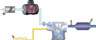
A slight digression from the topic
The illustration shows how tightly the mass air flow sensor is integrated into the control system of the electronic engine unit. The slightest failure in data exchange will instantly disrupt the formation of the fuel-air mixture. The result is a loss of power and increased fuel consumption.
It is important to know: a breakdown or even complete removal of the mass air flow sensor from the ECU system will not lead to the car stopping. However, prolonged operation without a sensor has a detrimental effect on engine life, not to mention ongoing financial losses.