December 17, 2020 Lada.Online 19 099 19
Good halogen car lamps can cost more than 1 thousand rubles. It will be a shame if they quickly burn out. To extend their service life, it is enough to implement their smooth ignition. After all, incandescent lamps most often burn out the moment they are turned on. You can modify the design yourself in two different ways.
Smooth switching on of LEDs with your own hands
Do-it-yourself smooth switching on and dimming of LEDs
I think everyone understands what smooth switching is, or otherwise the ignition of LEDs.
Let us examine in detail the smooth switching on of LEDs with our own hands.
The LEDs should not light up immediately, but after 3-4 seconds, but initially not blink or light up at all.
Device diagram:
Components:
■ Transistor IRF9540N ■ Transistor KT503 ■ Rectifier diode 1N4148 ■ Capacitor 25V100µF ■ Resistors: - R1: 4.7 kOhm 0.25 W - R2: 68 kOhm 0.25 W - R3: 51 kOhm 0.25 W - R4: 10 kOhm 0.25 W ■ Single-sided fiberglass and ferric chloride ■ Screw terminal blocks, 2 and 3 pins, 5 mm
You can change the ignition and decay time of the LEDs by selecting the value of resistance R2, as well as selecting the capacitance of the capacitor.
Using a utility knife, I made grooves along the marked lines, then sawed them out with a hacksaw and sharpened the edges with a file. I also tried using metal scissors - it turned out to be much easier, more convenient and dust-free.
Next, sand the workpiece under water with P800-1000 grit sandpaper. Then we dry and degrease the surface of the board with 646 solvent using a lint-free cloth. After this, it is not advisable to touch the surface of the board with your hands.
Next, using the SprintLayot program, open and print the diagram on a laser printer. You only need to print the layer with tracks without markings.
To do this, when printing in the program, at the top left in the “layers” section, uncheck unnecessary boxes. Also, when printing, in the printer settings we set high definition and maximum image quality.
Using masking tape, glue a glossy magazine page/glossy photo paper (if their size is smaller than A4) onto a regular A4 sheet and print our diagram on it. I tried using tracing paper, glossy magazine pages and photo paper.
Now we warm up the textolite and attach our printout. Then use an iron with good pressure to iron the board for several minutes.
Now let the board cool completely, then put it in a container of cold water for a few minutes and carefully remove the paper from the board. If it doesn’t come off completely, then roll it up slowly with your fingers.
Then we check the quality of the printed tracks, and touch up the bad places with a thin permanent marker.
The etching time depends on many parameters, so we periodically remove and check our board. We use anhydrous ferric chloride, dilute it in warm water according to the proportions indicated on the package.
To speed up the etching process, you can periodically shake the container with the solution.
After the unnecessary copper has been removed, we wash the board in water. Then, using a solvent or sandpaper, remove the toner from the tracks.
Next you need to tin the board. There are many different ways, I decided to use one of the simplest and most accessible. Using a brush, we lubricate the board with flux (for example LTI-120) and tin the tracks with a soldering iron. The main thing is not to keep the soldering iron tip in one place, otherwise the tracks may come off due to overheating. We take more solder onto the tip and move it along the path.
Now we solder the necessary elements according to the diagram. For convenience, in SprintLayot I printed out a diagram with symbols on plain paper and, when soldering, checked the correct arrangement of the elements.
After soldering, it is very important to completely wash off the flux, otherwise there may be shorts between the conductors (depending on the flux used). First, I recommend thoroughly wiping the board with 646 solvent, and then rinsing it well with a brush and soap and drying it
Result:
Relay manufacturing
| standard Kia relay |
As it turned out, Kia uses its own unique forms of relays, which you cannot find in shops on the street, only on order and for a lot of money. The relay is symmetrical four-legged: two diagonal legs are the coil, the other two legs are closed contacts. In general, this is convenient: you don’t need to think about which side to plug into the steering wheel, it will work either way. But in our case, maintaining polarity plays an important role; if you turn the relay the wrong way, this can lead to the power transistor burning out. Well, you will have to draw a warning notice on the case and be careful when installing.
| 95220-3A300 disassembled relay shunt for Kia |
But there was no need to disassemble the relay. As it turns out, my car has the option of daytime running lights. All you need to do is pull out the plug, which is shaped exactly like a relay, and insert a regular relay in its place. That's exactly what I did. I found this shunt plug in my hands.
Not only is such a shunt much more convenient for subsequent processing, but also when ordered, it will cost several times less than a whole relay.
| Prototype for experiments |
After some filing and finishing of the shunt, I began designing a board that would fit into this case. There is not much space inside: the board should not exceed 19mm in width and 18mm in height. The board had to be made double-sided. The sides are connected to each other at four points. To connect, I used pieces of legs left over from radio components.
For etching I used Laser Ironing Technology (LIT), printing the template on a laser printer on glossy photo paper for inkjet printing.
|
|
| ||||||||
|
|
| ||||||||
|
| |||||||||
Operating principle
To ensure a uniform increase in the applied voltage, it is enough for the phase angle to increase in just a few seconds. The current surge is smoothed out, and the coils gradually heat up. The figure below shows one of the simplest protective circuits.
Scheme of a device for protecting against burnout of halogen and incandescent lamps on a thyristor
When turned on, the negative half-wave is supplied to the lamp through a diode (VD2), the power supply is only half the voltage. During the positive half-cycle, the capacitor (C1) is charged. When the voltage across it rises to the opening value of the thyristor (VS1), the lamp is fully supplied with mains voltage, and the start-up ends with full glow.
Diagram of a lamp burnout protection device using a triac
The circuit in the figure above operates on a triac that allows current to pass in both directions. When the lamp is turned on, negative current passes through the diode (VD1) and resistor (R1) to the control electrode of the triac. It opens and skips one half of the half-cycles. Within a few seconds, the capacitor (C1) is charged, after which the positive half-cycles open, and the lamp is fully supplied with mains voltage.
The device on the KR1182PM1 microcircuit allows you to start the lamp with a smooth increase in voltage from 5 V to 220 V.
Device diagram: starting incandescent or halogen lamps with phase control
The microcircuit (DA1) consists of two thyristors. The decoupling between the power part and the control circuit is made by a triac (VS1). The voltage in the control circuit does not exceed 12 V. The signal is supplied to its control electrode from pin 1 of the phase regulator (DA1) through a resistor (R1). The circuit starts when the contacts (SA1) open. In this case, the capacitor (C3) begins to charge. The microcircuit starts working from it, increasing the current passing to the control electrode of the triac. It begins to gradually open, increasing the voltage on the incandescent lamp (EL1). The time delay for its ignition is determined by the capacitance value of the capacitor (C3). It should not be made too large, since with frequent switching the circuit will not have time to prepare for a new start.
When you manually close the contacts (SA1), the capacitor begins to discharge into the resistor (R2) and the lamp turns off smoothly. Its switching time changes from 1 to 10 seconds with a corresponding change in capacitance (C3) from 47 μF to 470 μF. The lamp extinguishing time is determined by the resistance value (R2).
The circuit is protected from interference by a resistor (R4) and a capacitor (C4). The printed circuit board with all the parts is placed on the rear terminals of the switch and installed together with it in the box.
The lamp starts when the switch is turned off. A glow discharge lamp (HL1) is installed for illumination and voltage indication.
Fast heating
This mode is only possible if the lamps are in a state of 50% filament power - in heat retention. When the light is turned on smoothly in 0.5 seconds. 80% power is achieved - sufficient to illuminate the road. And after 1.5 seconds. the lamps are burning at full power.
In any case, when the filament power is reduced to less than 50%, the lamps go out. Their subsequent activation occurs in a slow heating cycle. If, during the slow or fast heating process, the headlight switch opens at the moment when the lamp power exceeds 50%, a hold cycle begins.
How to smoothly switch on low and high beam headlights and what is this for? »
Drivers often ask how to smoothly switch on low and high beam headlights. This switching not only gives the car a more interesting appearance and has less impact on vision, but also increases the service life of halogen bulbs. To create this effect, it is necessary to achieve a smooth attenuation of the filament. This is a fairly common type of optics tuning.
At the same time, it does not cause any problems with traffic police officers, which is important in light of increasingly increasing fines. So, let's consider how this effect is achieved, and whether you need to spend your time on it
What gives?
How to smoothly switch on low and high beam headlights and why this is needed
. The main function of such a device is to protect the light bulb from burning out. To better understand the situation, let's consider it from the point of view of physics. Everyone knows Ohm's law, or guesses about its existence. Based on this rule, it follows that current strength is always inversely proportional to resistance. Formula I=U/R,
We probably saw everything at school. The filament of a car light bulb in a cold state has a resistance 10-12 times higher than when heated. When voltage and power are applied to it, the current also increases by the same amount. For a standard 55 W lamp, this figure can reach 60 Amperes.
True, this current strength does not last long, only until the coil warms up, after which the current strength decreases to normal levels. The light bulbs are designed for such an increase, and in theory nothing bad should happen. But everyone knows the ability of incandescent lamps to burn out when they are turned on. It's all about the uneven wear of the spiral. During operation, some areas evaporate faster for various reasons, the thinning spiral becomes more sensitive to increased current and burns out.
Smooth switching of the light does not provide maximum power from the very beginning, which prevents the current from increasing to dangerous levels. Thus, it is possible to significantly increase the service life of halogen lamps (see article “”). This is especially true for “white light” lamps, which have a shorter lifespan.
Ways to solve the problem
To eliminate the problem, it is enough to reduce the power that is dissipated during startup. To do this, it is necessary to reduce the current in this circuit. There are several ways to solve the problem:
- A fairly powerful field-effect transistor with a capacitor on the gate. The transistor initially passes a small amount of current. At the same time, its capacitor is gradually charged, opening the shutter. With a fully charged capacitor, the power goes entirely to the lamp, eliminating the need for a relay. The disadvantage of the scheme can be considered the need to remove a large amount of heat;
- with an NTS thermistor and relay
works similarly . In the case of a car, it is better to use a 2-5 ohm thermistor. It is connected in series to the lamp. At the same time, it dissipates part of the power. As the thermistor gradually heats up, it reduces its resistance. The power on the light bulb increases when this indicator reaches a certain level; a relay connected in parallel with the lamp disconnects the thermistor from the circuit, providing the lamp with maximum voltage; - Pulse width modulation
. Unlike those described above, this method does not limit the current, which reduces power dissipation. This reduces the need for cooling. The circuit uses a field effect transistor. Through it, voltage is not supplied to the light bulb constantly, but with pulses of several microseconds. Thanks to this, the coil heats up evenly. And the headlights gradually turn on.
Driver repair
First of all, check the fuse, if there is one. The device should show zero resistance. This can be done without removing the fuse from the board. Did the device show infinitely high resistance? Replace the fuse and plug in the lamp to test. Is it glowing? The renovation is complete. If the fuse is OK, we continue the repair. Check the diode bridge. You can find out in detail how to do this here.
Is the diode bridge working? Then unsolder the smoothing electrolytic capacitor and ring it. If the capacitor is working properly, then at the initial moment of continuity the multimeter will show a small resistance, which will grow before our eyes until it goes to infinity.
If the driver is simple, as often happens, then all these manipulations will certainly lead to success and completion of the repair. If the driver is more complex, then all you can do is ring the remaining electrolytic capacitors and diodes. It is easier to completely unsolder capacitors; only one terminal of a diode can be unsoldered. To make it lose contact with the board, it is enough to lift the device with a needle or tweezers.
If everything is in order here, then, alas, for further more complex repairs you will have to use the help of a qualified electronics engineer.
Tags: lighting, ceiling light, soft start
Comments 43
Tell me, is a bipolar transistor suitable here (KT837D)?
did you draw a signet in the sprint? if so, can you send it to me?
I'll look at it on my home computer in the evening, and if I have any left, I'll post it.
as a friendly criticism: 1. instead of a nickname, it would be better to leave a polygon for heat dissipation, and in general route the board so that there is no need to etch, but it would be possible to draw out isolated areas with a craft knife 2. do not solder the wires to the board , and connect it with a connector - when you want to improve the device, you could simply replace it
The heat dissipation is clearly unnecessary... The transistor is powerful, but the diodes in the lampshade consume just a little bit. It is higher than the ambient temperature and does not heat up. Regarding marking the board with a stationery knife - well, I don’t like this kind of collective farm. I’d rather spend an extra half an hour or an hour, but I’ll do everything beautifully. The connector is located, but not on the board itself, but on a five-centimeter piece of wire. This makes it more convenient to place the device under the ceiling - first stick it in place as it should, and then connect the wires.
and how did you etch the board? How did you apply it to the textile?
The tracks were applied using photoresist. Etched in a solution of hydrogen peroxide, salt and citric acid.
I remember, I used to paint paths with varnish... I etched them in ferric chloride))) don’t they do that anymore?))) Psst I’m behind...
Well, probably no one paints with varnish now, it’s easier to do it with the same LUT. But I myself used ferric chloride until recently, until I learned about the method with hydrogen peroxide - it’s easier to get, and cheaper, and it doesn’t stain everything around)))
and how did you etch the board? How did you apply it to the textile?
TextOlit. Actually, it’s fiberglass.
ok, that’s it, I was being clever...
If you like being illiterate, stay...
Do you often use textolite? since there was fiberglass here... I think it’s already clear what kind of material it is... there’s a mistake in the name - yes, I remember it correctly. But. I don’t think it’s a mistake to simply call the material for boards PCB. I think many people say this so as not to lengthen an already understandable word. It's like always adding a lead-acid battery to a car. I don't think you're adding either. fiberglass = textolite. the essence of what we are talking about does not change at all.
The fact is that PCB is a fabric impregnated with glue. It is brown in color. www.ru.all.biz/img/ru/catalog/2068698.jpeg It is not metallized and is not used for the production of printed circuit boards.
And fiberglass is fiberglass impregnated with epoxy resin; it is light yellow in color. And the properties of the materials are very different.
Getinax is also used as a dielectric for printed circuit boards - this is paper impregnated with glue. Also, by the way, brown.
Getinax is often used in household appliances (previously, only getinax was used). Fiberglass began to replace it a couple of decades ago.
Yes, I’ve been doing electronics for a long time, 40 years already. I designed and manufactured my first printed circuit board at the age of 12, i.e. in 1982...
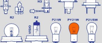
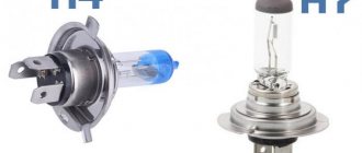
Types of halogen lamps.
There are many types and types of halogen light sources.
Linear. Tube-shaped lamps. Used to illuminate large areas: warehouses, workshops, streets. Used in spotlights. Such light sources are durable, bright, and powerful. But not energy efficient.
Capsule. Compact, small, low-power. Used for spot decorative lighting in cars. Suitable for open type lamps. Can be used with a reflector.
With reflector. Consist of a miniature light bulb with a dome-shaped reflector. Such lamps create directed radiation into a given space. Reflectors are either aluminum or interference. In the first case, heat is transferred forward, and in the second - back. They also produce light sources with a reflector with a protective cover. Used for lighting, table and wall lamps, in suspended ceilings, cars, spotlights.
With external flask. Designed to replace incandescent lamps. They are produced with standard sockets E14 and E27, which allows them to be screwed into ordinary chandeliers and lamps. The inner quartz bulb houses a miniature or tubular halogen light bulb. And the outer glass bulb is designed to protect the lamp from dirt and a person from burns. The outer flask is made in different shapes and colors.
IRC halogen lamps. An analogue of lamps with a reflector, which is coated with a special composition that reflects infrared radiation. The most energy efficient type. A special coating reflects infrared radiation from the tungsten filament back onto the filament. As a result, the tungsten temperature increases and heat loss decreases. As a result, electricity consumption is reduced and service life is increased.
Halogen chandeliers. Miniature, beautiful light bulbs are a good find for interior decoration. It is recommended to use ceramic cartridges to avoid overheating.
Low voltage. Light sources operating on 6, 12 or 24 V. The most common option is 12 V. Suitable for lighting flammable objects and rooms with high humidity levels. Used for safe lighting in museums, spot lighting, etc. Used to work in battery devices and vehicles. Connected via a step-down transformer.
GLs are divided according to the type of base. Depending on the purpose, size, and design, lamps are equipped with different types of sockets.
- To replace incandescent lamps, use halogen lamps with threaded sockets E14 and E27.
- Linear ones are equipped with an R connector
- For cars, lamps with H/HB socket are produced: H3, H19, H1, H11; HB4, HB3, etc.
- Low-voltage light sources are equipped with a GU 5.3, G4, GY 6.35, GU10, G9 or G12 pin base to prevent their installation in a 220 V network.
Types of socles.
Design Features
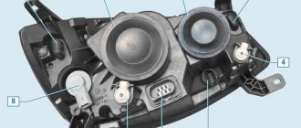
Lamps
. Cars use pod lights that combine passing and leading lights (single thread bulbs) and turn indicators. In addition, the headlights have parking light bulbs. The low and high headlight beams are activated using auxiliary relays K4 and K5 located in the mounting block. The control voltage to the relay coils is supplied from the headlight switch when the headlight switch switch is fully pressed. When the low beam is turned on, the low beam lamp comes on, and when the high
, all lamps (passage and movement) are illuminated.
turn on
in no time by pulling the light switch lever towards you.
In this case, the voltage at contact “30” of the switch is supplied directly from the power sources. In the wiring harness of wiring harness B for connecting the wires when installing headlights with low beam lamps with double hood. In this case, the gray wire with a red stripe in connector B must be connected to the same color wire as the switch's "56b" connector. Then, when the low
, the low beam bulb in the double brake lamps comes on, and when the high beam beam is switched on, the high beam bulbs in the double brake lamps and the headlight come on.
Fog lights
. On VAZ 2110 vehicles, in the optional version, fog lights can be installed on the front bumpers. The headlights are switched on by switch 27 (see Instrument panel) using an additional relay type 113.3747 installed in a shoe attached to the rear side of the mounting block. The fog lights can only be turned on if the exterior light
26.
Accelerated self-training course for novice drivers: Sign up for lessons.
https://youtube.com/watch?v=6XsMfAPBhtw
HOW TO CONNECT AUTOMATIC LOW BEAM
, THERE IS CONTROL OF LIGHT OPERATION AND.
Outdoor Lighting
. The ambient light is turned on by the external lighting switch 26 (in positions “I” and “II”). The parking light and brake light lamps are supplied via lamp control relay K1. If any lamp is on, the relay is activated by the corresponding LED indicator in block 5 (see Instrument panel) of the on-board monitoring system.
Direction indicators
. The direction indicators for the starboard or port side are activated using the switch lever. In emergency mode, switch 42 turns on all direction indicators. The flashing of the lamps is ensured by the KZ relay switch in the mounting block.
Using Dimming
Smooth switching on of incandescent lamps can also be done with dimmers or dimmers.
The name dimmer comes from the English “dim”, which means to dim. Here, the voltage level is adjusted automatically or mechanically (by rotating the knob) in a way. For simple dimmers, the control circuit is built on a rheostat - a variable resistor. Now semiconductor triac or transistor switches are used for these purposes. In modern electrical engineering, devices with a timer, sensor or remote control are mainly used to smoothly switch on 220 W incandescent lamps. Typically, dimmers are installed instead of a standard switch. Important! When installing a dimmer on incandescent lamps, it is impossible to achieve energy savings. Reducing light levels by 50 percent saves only 15% of electricity
Dimmer connection diagram
In rotary dimmers, the intensity of halogen lamps is adjusted by turning the potentiometer knob. In electronic ones, all parameters are set automatically.
Additional Information. The dimmer may interfere with sensitive measuring devices and radio receivers. The use of the device sometimes causes additional background noise during the operation of sound recording equipment. All this must be taken into account when installing devices.
You can assemble a simple regulator with your own hands.
The scheme consists of:
- BT134 – 700 V triac, which can be replaced with KU208G, MAC212-8, MAC8S, BT138 or BT136;
- DB3 – dinistor, you can also use KN102, HT40 HT34, HT32, DC34, DB4;
- a non-polar capacitor with a capacity of 0.1 to 0.22 µF (250 V);
- resistor (10 kOhm) with a maximum power from 0.25 to 2 W;
- compact variable resistor (resistance level approximately 500 kOhm);
- wires for connection to the main circuit.
Homemade brightness control circuit
The assembled device is sequentially installed in the zero phase of the wire going to the lamp. A triac allows current only at a certain potential difference. Charge accumulation occurs on a capacitor, which is connected to a triac. In this case, the charging speed is determined by the resistance level of the variable resistor. The very level of this resistance is set by the user. The lower the resistance of the variable resistor, the brighter the lamp burns.
The advantage of this homemade device is that during operation there is no drop in the voltage level, and the illumination does not suffer. On the other hand, a smooth start of a halogen lamp is achieved by mechanically turning a triac, the speed of which is difficult to adjust. Precise parameters can only be set on modern automatic devices, which are more difficult to assemble with your own hands.
When choosing a dimmer device for smoothly switching on an incandescent lamp, it is necessary to take into account that some types of equipment start working from a minimum value when the filament glows slightly. Others immediately give a significant jump, which also leads to a large voltage drop across the lamp.
Using a dimmer may result in increased magnetostriction and high-frequency whistling or noise coming from the incandescent lamp. This phenomenon is typical for high-power incandescent lamps. If the lamps operate without a dimmer, then the additional sound is almost inaudible.
Light sensor failure
As a rule, such devices rarely break down on their own. Provided that you have chosen a quality product from a well-known brand. When it comes to safety while driving, there is no need to skimp. Breakdowns are usually caused by factory defects, improper installation or improper use. It often happens that it takes many hours to find a fault, but the repair itself takes only a few minutes.
Many manufacturers indicate some restrictions for their products, so you should carefully read the instructions
As a rule, these are standard precautions: make sure that no moisture gets inside the device elements, protect them from mechanical and other influences. There are also sometimes recommendations not to use gas-discharge lamps on cars.
Well-known manufacturers of dimmers
Among the famous brands it is worth highlighting:
- Schneider Electric (France). The devices of this company advantageously combine exclusive design and excellent build quality.
- Teco (Czech Republic). Dimmers of this brand offer reliability, long and trouble-free service at an affordable price.
- Jung (Germany). Dimmers are distinguished by their original design, functionality and outstanding performance parameters.
- Legrand (France). The company focuses on the production of new generation high-tech models, widely used in smart home systems.
- Gira (Germany). Dimmers of this brand are distinguished by their long service life, discreet design and reliability.
Do-it-yourself automatic low-beam headlight switching
July 27, 2016. Category: Automotive equipment.
As you know, low beams must be turned on when driving a vehicle, not only in the evening and at night, but also during the day. In a situation where the running lights do not work, the traffic police officer has the right to issue a fine to the driver.
Of course, this is a small amount, but it creates a headache.
In this regard, most motorists have encountered a number of inconveniences due to the fact that many simply forget to turn on the low beams when getting into the car, or do not turn off the lights when leaving the car, which is why they find the battery completely discharged in the morning.
In order to get rid of such problems, many decide to modify the process of turning on and off the headlights. Thanks to the simplest circuits, the headlights can turn on simultaneously with the ignition or when the engine starts. In this case, during the daytime the low beam headlights will light up, but not the headlights, and at night everything will work as usual. Let's consider both options.
Automatic switching on of headlights upon ignition
In order to organize such operation of the lighting elements, it is necessary to connect them to the ignition power source, and as many know, some devices can be connected at any position of the ignition switch, while others begin to function only when the ignition is already on. Based on this, the most convenient place to connect the headlights is the heater switch button (the rightmost switch block).
For this scheme you will need:
- any standard five-pin relay;
- diode;
- wires.
Next, we need:
- Remove the size switch (switch block on the leftmost side).
- Disconnect the positive wire from the key block responsible for the low beam operation (usually this is a green double wire) and connect it to the relay.
- You need to insert an additional wire into the positive wire that goes to the heater switch and also connect it to the relay.
- Connect the wire that powers the headlights to the relay.
- Throw the wiring to minus (to the body).
The connections can be soldered, but for full-fledged work, an ordinary insulated twist will suffice. As a result, automatic low beam headlights will work as soon as you turn on the ignition.
However, this method is considered not the most economical, since the headlights start working immediately, which is not very important in winter, when the engine needs to be warmed up or when repairing a car.
To avoid such inconveniences, you can complicate the circuit a little so that the low beam turns off while parked, regardless of whether the ignition is working or not.
Automatic switching on of headlights after engine start
To organize such a work scheme, you can go in two directions: connect to the oil pressure sensor or to the handbrake.
Method 1: Connecting to the oil pressure sensor
To make this connection you will need:
- relay;
- transistor (2 pieces);
- wires;
- microcircuit K561TP1.
All parts are placed in a small relay housing, after which the device must be connected to an oil pressure sensor. When the pressure in the engine lubrication system normalizes, that is, when the engine is turned on, the sensor will open, and the power from it will go to the capacitor.
Ultimately, the voltage to the relay will be supplied through the transistors included in the headlight power supply. When the engine is turned off, power from the sensor is supplied to the desired lamp located on the dashboard.
At this time, the capacitor that is included in the headlight control unit begins to discharge and the power supply to the relay stops.
True, not everyone likes this method, since this scheme is much more complicated (you need to pull wires and make 3-4 connections).
Method 2: Connecting to the handbrake
This method is much simpler, since in this case it is enough to just slightly modify the headlight connection diagram for ignition, which we talked about at the very beginning. To do this, just add another relay and a short wire (about 25 cm) to the standard contact of the handbrake button.
Thanks to this method, the headlights will turn off as soon as you pull the handbrake, and light up when you release it.
In custody
All these methods take a minimum of time and financial investment, and the result eliminates many troubles. Automating the process of turning on headlights does not require any special electrical skills, so you can handle this connection yourself without any problems.
Microcontroller program
The program implements a finite state machine that is in one of six states:
— the ignition was turned off, waiting for the headlights to turn on.
- smooth warm-up
— the light has already turned on, waiting for the headlights to turn on again
- quick warm-up
— lamp is on 100%
— holding and extinguishing after turning off the headlights.
PWM is implemented using the “phase-correct PWM” timer mode operating at the processor frequency. This mode provides full shutdown and full turn on at extreme values of the PWM parameter, and one period takes 510 processor cycles. When the microcontroller operates at a frequency of 1.2 MHz, the pulse frequency is 2353 Hz.
State machine states are processed in the timer overflow interrupt handler.
// Timer interrupt, executed 2353 times per second ISR(TIM0_OVF_vect) { if (countdown > 0) { countdown—; return; } switch (current_state) { case STATE_SLOW_WARM: { // slow warm-up uint8_t o = PWM_OC; if (o >= 254) { PWM_OC = 255; current_state = STATE_ON; } else { o++; PWM_OC = o; if (o < SLOW_RAMP_VALUE) { countdown = SLOW_RAMP_SPEED; } else if (o == SLOW_RAMP_VALUE) { countdown = SLOW_RAMP_HOLD; } else if (o < SLOW_WARM_VALUE) { countdown = SLOW_WARM_SPEED; } else { countdown = SLOW_LAST_SPEED; } } } break; case STATE_FAST_WARM: { // fast warm-up uint8_t o = PWM_OC; if (o >= 254) { PWM_OC = 255; current_state = STATE_ON; } else { o++; PWM_OC = o; if (o < FAST_WARM_VALUE) { countdown = FAST_WARM_SPEED; } else { countdown = FAST_LAST_SPEED; } } } break; case STATE_HOLD: { // hold after disconnect uint8_t o = PWM_OC; if (o <= 1) { PWM_OC = 0; current_state = STATE_LIGHT_OFF; } else { o—; PWM_OC = o; countdown = HOLD_FALL_SPEED; } } break; } }
There is also an interrupt that monitors changes in logic levels at inputs PB3 and PB4. If such a change is registered, regardless of which input, the state of both inputs is evaluated, and depending on this and the current state, the machine is transferred to one state or another.
// Interrupt for any change in logical levels at the “ignition” and “light switch” inputs ISR(PCINT0_vect) { if (is_ignition_on()) { if (is_switch_on()) { // If the ignition is on and the switch is on. switch (current_state) { case STATE_IGNITION_OFF: current_state = STATE_SLOW_WARM; countdown = 0; break; case STATE_HOLD: case STATE_LIGHT_OFF: current_state = STATE_FAST_WARM; countdown = 0; break; } } else { // If the ignition is on, but the switch is off switch (current_state) { case STATE_SLOW_WARM: if (PWM_OC >= HOLD_VALUE) { PWM_OC = HOLD_VALUE; current_state = STATE_HOLD; countdown = HOLD_COUNTDOWN; } else { current_state = STATE_IGNITION_OFF; PWM_OC = 0; countdown = 0; } break; case STATE_FAST_WARM: current_state = STATE_HOLD; if (PWM_OC >= HOLD_VALUE) { PWM_OC = HOLD_VALUE; countdown = HOLD_COUNTDOWN; } else { countdown = 0; } break; case STATE_ON: PWM_OC = HOLD_VALUE; current_state = STATE_HOLD; countdown = HOLD_COUNTDOWN; break; } } } else { // If the ignition is off, then off, no options. current_state = STATE_IGNITION_OFF; PWM_OC = 0; } }
The main body of the program does not perform any actions, but simply cyclically puts the microcontroller into idle mode.
set_sleep_mode(SLEEP_MODE_IDLE); sleep_enable(); sei(); while(1) { sleep_cpu(); }
In the microcontroller settings, the voltage drop protection mode (Brown-out detector) is enabled and set to a level of 2.7 Volts. When the voltage drops below this level, the microcontroller enters a reset state.
The delay after reset is set to 64ms (default setting).
Overview of the main options and their features
We will look at how to automatically turn on the low beam in two ways, each of them has its own characteristics, and the choice ultimately depends on you.
Domestic manufacturers suggest using a special relay as a solution to the problem, its marking is 719.3777-01, with its help you can automatically turn on the low beam and side lights.
The following can be said about this option:
- The system is suitable for VAZs from the 4th to the 15th model, for example, the relay is installed for fog and regular headlights in the VAZ 2110, GAZ, UAZ and others, in which the low beam winding of the relay has a permanent connection to ground;
- The headlights light up approximately 5 seconds after the engine starts, which is very convenient, since, firstly, it makes it easier to start the engine, secondly, the load on the battery is significantly reduced, and thirdly, the life of the lamps increases;
- The lights turn off when the ignition is turned off, which is also very convenient, because now you won’t leave the car with the headlights on;
- If necessary, you can always turn off the light manually; to do this, the switch is flipped to the “low beam” position, and then placed in the “off” position.
Now let’s look at how to implement automatic switching on of low beam headlights with your own hands; the work is carried out in the following sequence:
First, you need to install a new unit instead of the low beam relay, and if you use mini-relays, you will need a special adapter, which should also be included in the kit, the whole process is as simple as possible and will not take much time;
By going through this process, you will get a convenient and reliable system that will prevent many problems.
Benefits of installing the system
First, we will look at the main advantages that using automatic light switching options gives us:
| Convenience | Now you will not forget to turn on the lights, and you will not be fined by the traffic police. As practice shows, the majority of such offenses are committed precisely because drivers forget to turn on the lights when starting to drive. In addition, you will not have to be distracted, you will know that the system works automatically at a certain point in time |
| Battery preservation | As practice shows, very often after finishing driving, drivers forget to turn off the lights, as a result of which the battery runs out; if such cases are repeated periodically, the battery will fail very quickly. The presence of such a system allows you to eliminate such troubles, because the shutdown will also be carried out automatically |
| Ease of work | You can easily implement any of the options described below with your own hands; the installation instructions are simple and clear, so you can do it without outside help, especially since the delivery set includes all the elements necessary for installation. The main thing is to be careful and use only high-quality connection methods; twisting and electrical tape are unacceptable |
| Low costs | The price of the required elements is low, so you will not incur large expenses. The most important thing is to choose a high-quality option that will ensure good system operation |
Important! The big advantage is that you can customize the operating features of the system to suit yourself, this allows you to use devices of this kind on almost any car model.
Thyristor circuit
This scheme can be recommended for repetition. It consists of common elements that gather dust in attics and closets.
In the circuit of the rectifier bridge VD1, VD2, VD3, VD4 there is an incandescent lamp EL1 as a load and current limiter. The rectifier arms contain thyristor VS1 and a shifting chain R1 and R2, C1. The installation of a diode bridge is determined by the specific operation of the thyristor.
After applying voltage to the circuit, current flows through the filament and enters the rectifier bridge, then the electrolyte capacity is charged through the resistor. When the voltage reaches the opening threshold of the thyristor, it opens and passes the incandescent light bulb current through itself. This results in a gradual, smooth heating of the tungsten coil. The warm-up time depends on the capacitance of the capacitor and resistor.
Connection using a protection unit
Typically, to solve this problem, a protection unit is used, which performs the function of the UPVL. When used with incandescent lamps of this device, the voltage when turned on does not increase so sharply, but gradually increases. Thus, the filament does not experience unnecessary overloads, and the life of the light bulb increases.
Let's take a closer look at the operating diagram of this device using the example of a Uniel Upb-200W-BL unit connected in series to a 75 W incandescent lamp. In this circuit, the current first passes through the block and only then goes to the lamp. As a result, an additional voltage drop occurs, and the lamp receives not the standard 220, but 171 V. Moreover, due to the passage of current through the protection unit, the voltage increases to 171 V smoothly in 2-3 seconds.
Uniel Upb-200W-BL for smooth startup
Reducing the incoming voltage also helps to increase the life of the light bulb. But, on the other hand, the reduced voltage significantly reduces the luminous flux, by approximately 70 percent, and this is a significant indicator. Therefore, when using a protection unit, it is necessary to take into account illumination losses and use lamps that are more powerful than conventional ones.
The unit considered in our diagram can withstand power up to 200 W, which means that lamps of approximately the same power can be connected to it. But it is better to set a small margin of 20-25 percent and use lamps with a total power of no more than 160 W in the circuit. Due to the power reserve, the lamps and the unit itself will last longer. Naturally, you should not apply voltage more than 200 W to the unit itself.
Note! As the incandescent lamp's wattage is lowered, the color temperature changes and the light becomes redder. Changes in lighting color can affect a person's well-being
The scheme for smoothly switching on incandescent lamps is quite simple. The block is installed in series from the switch to the lamp, that is, in the break of the phase wire.
The protection block itself can be placed in two places:
- next to the lighting fixture;
- at the switch - in this case the unit is located in a distribution or installation box.
Protection block placement
The choice of location depends on the size of the protection unit; for a device that is too large, you will have to allocate a separate place. The disadvantage of placing it in a socket box is that the protection unit will not have sufficient air access for cooling.
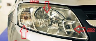
The procedure for connecting the Smooth Ignition Unit (SBU) to the low beam
You will need:
- 4 moms wide
- 4 dads wide
- 2 moms are narrow
- 2 dads are narrow
“Tee” for branching on the mass mounting block
We connect the “mother” and “father” connectors to three long wires (35 centimeters each). It turns out something like an extension cord for the low beam relay. We connect the “female” and “male” connectors to the BPR wires (Input +12V - “female”, Output - halogen - “male”).
Having pulled out the low beam relay (let me remind you K4), we attach an “extension cord” to it to all contacts except 87.
For convenience, you can fasten the “extension” with ties. On the right is ground (green wire - to the fuse box)
We insert the end of the “extension cord” into the fuse box instead of the relay.
At the other end - respectively, the relay that was pulled out earlier.
In the relay on the 87th “leg” we put the “female” connector from the BPR (+12V input), and insert the “male” connector (Output - Halogen) into the fuse block, where “leg” 87 should be.
The final version of the assembled structure.
We take the mass (mass -12 V) from somewhere more convenient (for example, from block Ш2 of the mounting block - contact 4. We take out the wire (black) from the block, instead of it we insert the prepared “tee” from the BPR.
To conveniently secure the relay inside the fuse box, you can buy a relay socket with a latch. And secure it to the back wall of the mounting block.
We insulate each contact (heat shrinkage, corrugation)
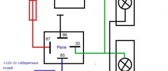
Connection diagram:
Which switch to choose with regulator
Today on the electrical appliances market you can see and get acquainted with a large assortment of monoblock type dimmers.
The most popular options are:
- Dimmers with a mechanical regulator. It is made in the form of a disk that rotates in certain directions. This is the simplest design and perhaps due to this its price is not so high. This type also includes dimmers, which include a push or turn mechanism. The first option works by closing the electrical circuit, the second will always turn on the electricity from the minimum stage.
- Push-button controls. They are presented as more complex structures. Their peculiarity lies in a number of additional functions. In addition, they can be combined into blocks, and control can be carried out through remote control using a remote control.
- Touch-type light controllers. This is quite expensive, but also the most prestigious installation at the moment. It can fit into any room interior, which is decorated in a modern style. In addition, a nice addition to such a dimmer would be to equip it with a signal receiver, which allows it to operate remotely.
In addition to the above options, there are also monoblock designs that include modular control. It can be carried out using a remote button or using a key switch. However, in residential premises such options are practically not found. They have found their application in public institutions and in distribution boxes.
A switch with a regulator called Legrand is very popular at the moment. It smoothly adjusts not only chandeliers, but can also be suitable for floor lamps. Separately, we note that the Legrand with light control is easy to repair if it breaks; very often users complain that it is humming, in order to fix this you will need a circuit.