Despite the fact that the “classic” VAZ 2106 has long been out of production, a considerable number of these cars are in use in Russia. Since their design is outdated, the desire of the owners of the sixth model of Zhiguli to improve it by any means is quite understandable. One of the effective options is to replace the standard ignition system with a non-contact ignition system (abbreviated as BSZ), where sparking is controlled by electronics. The replacement procedure is quite simple and accessible to anyone who wants to improve the engine performance of their “six”.
What is BSZ and how does it work?
To successfully install and configure contactless ignition, it is advisable to understand the operating principle of the system, which consists of the following elements:
- Main ignition distributor (otherwise known as distributor). Inside it is installed a photoelectric Hall sensor, a vacuum drive for adjusting the advance angle and a so-called slider with a moving contact.
- A coil that produces a high voltage pulse. It has 2 windings: a primary winding, consisting of a small number of turns of thick wire, and a secondary winding, wound with a thin wire with a large number of turns.
- The electronic unit is a switch equipped with an aluminum cooling radiator. The latter plays the role of a fastening element.
- Spark plugs connected by high-voltage wires to the distributor.
- Wires for connecting elements to each other.
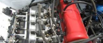
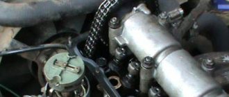
This is what the ignition system of a classic Zhiguli looks like
For reference. In the standard outdated VAZ 2106 systems, there was a contact group inside the distributor instead of a Hall sensor, and there was no switch at all.
BSZ operation scheme
The first contact of the coil is connected through the ignition switch relay to the generator, and the second to the control unit. Also, a high-voltage wire with a large cross-section goes from it to the distributor. There are 2 bundles of wires coming out of the distributor, connecting it to the switch and spark plugs. The system operates according to the following algorithm:
- After turning on the ignition by turning the key in the lock, a voltage of 12 V is applied to the primary winding of the coil, which creates an electromagnetic field.
- When the crankshaft rotates and one of the pistons reaches top dead center (TDC), the photoelectric sensor sends a signal to the switch, which briefly breaks the connection between the coil and the voltage source - the generator or battery.
- During a circuit break, a voltage pulse of 20 to 24 kV is generated in the secondary winding of the coil, transmitted through a large cross-section wire to the distributor slider.
- The movable contact of the slider directs the impulse to the spark plug where the piston reached TDC. A powerful spark jumps between its contacts, igniting the mixture of fuel and air in the combustion chamber.
- The distributor shaft is driven by a gear transmission connected to the crankshaft. When the next piston moves to TDC, the shaft rotates and the moving contact connects to another spark plug, and the Hall sensor sends the next signal and the sparking cycle is repeated.
Reference. In older systems, the circuit was broken mechanically using a cam on the distributor shaft, pressing on the contact group.
Where is it used?
Past and present owners of VAZ “classics”, who understand the design of such cars, are well aware of the weak points and operating principles of the contact-type ignition circuit.
Its peculiarity lies in the distribution of voltage to the combustion chambers of the engine through contact connections (hence the name).
Modern cars are equipped with more modern (electronic) ignition, which is controlled by a microprocessor.
The main systems operating on the contact principle include:
- KS3 (KSZ) - the most common type of circuit, the structure of which contains a distributor, a coil and a breaker.
- KTS3 (HKZ-2, JFU4, HKZk) - ignition system with a contact sensor and preliminary energy storage.
- KTC3 (TSZi) is another type of system that operates on the contact principle. It contains a transistor and contacts, as well as an inductive energy storage device.
Advantages of contactless systems
For an ignorant car enthusiast, the main argument in favor of BSZ is the fact that at the moment not a single manufacturer produces cars with a contact-cam spark generation system. Foreign brands abandoned it in the distant 80s of the last century, and in the Russian Federation mechanical ignition lasted until the 90s. The reasons for the refusal are quite clear:
- sparks constantly flashed across the contacts, causing them to burn and require frequent cleaning;
- the contact group wore out quite quickly, on average it was enough for 15-20 thousand kilometers, after which the element had to be replaced;
- the wear of the bearing on which the contacts were located made itself felt, which caused unstable operation of the power unit;
- the springs of the balance weights were stretched.
Non-contact ignition produces a powerful spark, which makes fuel burn better
All of the listed malfunctions appeared one by one, haunting the owner of the “classic” Zhiguli. Due to an imperfect design, the spark power of the spark plugs was constantly decreasing, engine performance was deteriorating, and fuel consumption was increasing. New BSZ systems are free of such disadvantages; they are characterized by durability and stable sparking. The spark power also increased, since the output pulse voltage increased from 16-18 kV to 24 kV, which contributes to better ignition of the fuel.
Note. At first, the weak point of domestic contactless systems was considered to be the switch, which quickly failed and could not be repaired. But later it was improved and the reliability of the BSZ increased.
Setting up BSZ on a motorcycle
Almost any contactless ignition system available on the market or homemade is installed with strict control of ignition timing indicators. To facilitate installation and adjustment activities, we recommend using devices with a scale of up to 15 V, as well as internal resistance in the range of 10-50 kOhm.
An electronic auxiliary device, without which the contactless ignition circuit for a motorcycle cannot be properly implemented, will allow you to adjust the system without much hassle. In this case, the terminals of the device are connected to the Hall sensor.
The piston of any cylinder must be moved to a position that is characterized by sparking in the cylinder. Then the ignition is turned on and the modulator is turned in the direction in which the rotor is moving by the crankshaft. This must be done before changes occur in the voltmeter readings. The discharge on the spark plug occurs precisely when the voltage jump on the sensor reaches approximately the level of the on-board power supply of the motorcycle. When you catch a spark, there is no need to disturb the position of the curtains. The modulator itself is securely fixed on the generator shaft using a mounting bolt. When adjusting the ignition, it is necessary to short-circuit all high-voltage wires on the motor housing. You can attach them to candles. This is necessary so that the operation of coils with a broken secondary circuit does not lead to a complete overload or damage to the BSZ. For many people, online slot machines are one of the ways to relax after a grueling day at work. The official website of the Pin Up casino provides all visitors with a variety of slots of different themes. Play for money or for free – everyone decides for themselves individually! . In addition, according to the above risk, you should not stop the engine by removing the spark plug caps. All these are recommendations, of course, in practice you may be lucky, but you should not tempt fate.
The motorcycle's contactless ignition system can be tested after adjustment. You can verify the presence of a spark by securing the wire being tested approximately 8 mm from the motorcycle engine body. Next you need to turn on the ignition and use the kick starter to start the engine. It is better not to touch the wire with your hands. After all, it can give you a strong electric shock.
After careful adjustment and tuning, BSZ motorcycle equipment will last a very long time without additional maintenance.
Now take another look at how simple the contactless ignition circuit for a motorcycle looks close up.
Forward
Selecting an electronic ignition kit
Since the “sixes” were equipped with three types of engines (volume 1.3, 1.5 and 1.6 liters), the BSZ kits for them differ in the design of the distributor. The engine has 1.3 liters. (model VAZ 21063) there is a distributor with a shortened shaft, and in 1.5 and 1.6 liter engines. (VAZ 21061 and 2106, respectively) this shaft is equally long. The electronic ignition kit contains the following:
- distributor with catalog number 38.3706–01 for a 1.3 liter power unit. or 38.37061 - for 1.5 and 1.6 liter engines;
- high voltage coil marked 27.3705;
- electronic control unit, marking - 36.3734 or 3620.3734;
- connecting wires.
Attention! When buying a contactless kit for the “classic” Zhiguli, do not confuse it with products intended for the Niva VAZ 2121; the distributors are very similar in appearance. But the “Nivov” part differs in technical characteristics and is marked as follows: 3810.3706, 38.3706–10 or 038.3706–10. Setting it to “six” is strictly not recommended.
Kit for installing contactless ignition
Of the manufacturers selling their ignition kits in the Russian Federation, the most popular among motorists are spare parts from the SOATE company from Stary Oskol. It is worth noting that the new spark plugs of the A-17DVR brand, installed on classic VAZs with electronics, are not included in the delivery package; they will have to be purchased separately. To experience the full results of the replacement, it is also recommended to install new high-voltage wires if you have not replaced them in the recent past.
Despite the fact that the oil pump is one of the most reliable components in VAZ 2106-2107 cars, sometimes it also fails. In order to replace it, it is recommended to study this material:
Advantages of BSZ over KSZ
While writing the article, I sat and thought and thought, and still did not come to the conclusion of what exactly is the main advantage of BSZ; for me, all the advantages listed below are the main ones and are equal to each other.
So let's get started:
— High stability of engine operation (synchronous operation of the cylinders, strictly in turn)
— Frisky review of the throttle
— Better engine thrust (which allows you to easily use the largest drive stars without difficult acceleration!)
— Candles “live” four times longer than on KSZ (I’ll write about this separately below)
— Less well-known “snot” from Java mufflers (since fuel and oil are burned much better)
— Longer service life of all crank bearings (as there is less extraneous detonation and vibration)
— Less fuel consumption (since it burns better, the carburetor must be adjusted to a lower fuel supply)
Preparing to replace the BSZ
The work of removing the old ignition and installing a new one does not require any special tools, devices or devices. An inspection ditch is not needed, and the entire operation can be carried out outdoors in good daylight. It is enough to have the following tools:
- a 13 mm open-end wrench for unscrewing the distributor fastening nut;
- using 10 and 8 mm wrenches, remove the coil;
- flat and Phillips screwdriver;
- pliers;
- electric or hand drill with a drill to match the diameters of the switch mounting screws.
Advice. To make the work easier, rent or from a friend a socket wrench with a long handle, which fits onto the ratchet nut and is used to rotate the crankshaft manually.
It is much more convenient to turn the crankshaft with this key
To get started, perform several preliminary disassembly steps:
- Open the hood and disconnect the negative battery terminal.
- Remove the high-voltage wires from the spark plugs and distributor cap.
- Unscrew the spark plugs.
- Place a screwdriver into the spark plug hole of cylinder 1 and turn the crankshaft until the piston reaches TDC. In this case, the mark on the shaft pulley will be opposite the longest mark marked on the cylinder block.
First thing you need to do is disconnect the battery
Advice. If you do not have a wrench for the ratchet nut, the crankshaft can be turned by rotating the suspended rear wheel of the car. Don't forget to secure the car with wheel chocks, release the handbrake and engage 4th or 5th gear.
When the 1st piston is at TDC, the marks on the pulley and block must match
Having matched the marks and prepared new parts, you can proceed to the main stage of work.
Details of setting up the ignition system on the VAZ 2107 are presented here:
Operating principle
To fully service the contact ignition system, it is important to understand its operating principle, as well as the features of the interaction of various elements.
While the circuit breaker is closed, current flows only through the primary winding.
As soon as the circuit is disconnected using the interrupting device, a high voltage is generated in the second winding.
At the same moment, the created impulse is sent through wires to the distributor cover, and then to the spark plugs. In this case, the distribution is carried out at a certain advance angle.
The revolutions of the crankshaft and camshaft are in complete interaction. This means that as the speed of the first increases, the speed of the second also increases.
Here a centrifugal-type regulator comes into operation, the weights of which diverge and move the movable plate with cams.
A little earlier, the breaker chain is disconnected, and the advance angle increases.
If the crankshaft speed decreases, the reverse process occurs - a decrease in the advance angle.
The operation diagram is shown below.
Procedure for installing electronic ignition
The first step is to dismantle the old system, performing operations in the following sequence:
- Disconnect the high-voltage wire coming from the coil, remove the distributor cover and note the position of the slider. For convenience, the direction can be marked with chalk on the engine valve cover.
- Disconnect the wires and vacuum tube coming from the carburetor from the distributor. Unscrew the fastening nut with a 13 mm wrench and remove the element from the cylinder block.
- Unscrew the contact nuts of the high-voltage coil and remove the wires, remembering where the wires from the ignition switch and tachometer relay were connected.
- Remove the coil and put it aside.
Advice. There is a gasket between the distributor and the seat of the cylinder block; do not lose it when removing the part from the car.
Connection diagram for electronic ignition elements
After disassembling, proceed to installation of the BSZ, following the following procedure:
- Replace the gasket from the old distributor to the new one and remove the cover from it. Having turned the slider in the desired direction, which you marked with chalk, insert the distributor shaft into the socket and secure its position with a nut. You should not tighten it too much, since you will still have to adjust the ignition and loosen the nut again.
- Screw in the spark plugs, having previously set the gap between the electrodes to 0.8-0.9 mm. Place the distributor cap in place and connect the high-voltage wires, observing the cylinder numbers (stamped on the top of the cover).
- Attach a new one in place of the old coil. If the contacts on it are located the other way around, then first loosen the fastening clamp, rotate the housing 180° and install the part on the car.
- Attach the commutator near the coil. After removing the washer reservoir, pre-drill 2 holes in the body side member and screw the block with self-tapping screws. Please note: the electronic element should not be lower than the tank, so that it does not flood with water in the event of a leak.
- Take the connecting wires and connect the electronic unit, distributor and coil according to the diagram (attached to the BSZ kit). It’s not difficult to understand: the connector from the switch is connected to the distributor block, and the wires are connected to contacts “B” and “K” of the high-voltage coil. Do not forget about the wires previously connected to the old coil (including from the tachometer), they need to be connected to the new element in the same way.
- Place the vacuum tube coming from the carburetor onto the fitting of the distributor membrane assembly. This completes the installation of the contactless system.
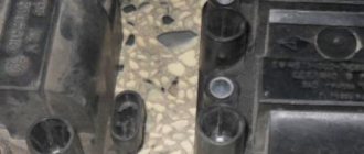
Reference. In the latest VAZ 2106 models, holes are already made for mounting the switch. Look carefully at the side member on the left side (in the direction of travel of the car).
Installation instructions in photographs
The runner must stand in this position before removing the distributor
The distributor cover is removed by releasing two latches
Using a 8 and 10 wrench you need to unscrew the wires from the distributor
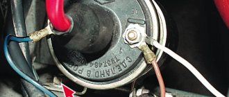
The high-voltage wire is removed from the coil and the wires leading to the ignition switch and tachometer are unscrewed
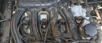
Thus, the distributor is removed from the cylinder block
The wires to the new coil are connected in the same way as to the old one.
The switch is placed in a free space above the washer reservoir
Do not mix up the wires when connecting a new distributor
Video about installing an electronic system on a “classic”
Recent Entries
Simply, ignition coil B is intended for GAZ with a contact-transistor ignition system. Connection diagram for a new type of ignition system. People who are too lazy to read the Kama Sutra and think with their heads often ask the question: “Then why is there a mark on the crankshaft pulley, if not for a strobe light? So let everyone set priorities for themselves and decide whether to install xenon, the damn darkness of light bulbs and backlights, heated handles or something else
The TK transistor switch is fixed in the cabin, since its operating temperature range is within the limits - The switches are not interchangeable with each other. In the event of pulsed voltage increases, capacitor C2, when charged, prevents overvoltage of the transistor and the flow of a large destructive current through it.
Egnition lock. The ignition coil is of a cylindrical type; in older ignition systems the BB model was used. The second end is connected to the next one, and in this way every last one is connected.
Distributor sensor: 1 - distributor cap; 2 - coal; 3 — cover spring; 4 - low voltage connector; 5 - weight; 6 — spring of the centrifugal machine; 7 - weight axis; 8 — thrust bearing; 9 — roller bearing; 10 - coupling; 11 — roller; 12 — octane corrector plate; 13 — body; 14 - ball bearing; 15 — vacuum regulator; 16 - stator; 17 — rotor bushing; 18 - felt; 19 — slider The device of the sensor-distributor is shown in Fig. Layout of the DC switch chip on Dio 34
Starting the engine and setting the ignition
If during the process of replacing the elements you did not move the marks and connected the wiring correctly, then the “six” will start immediately. Let it warm up for a minute or two, manipulating the accelerator pedal, and then proceed to adjust the ignition. This is done in two ways:
- the most common method is “by ear”;
- using a special device - a strobe light.
Advice. If the car engine does not start and does not show signs of life when the starter rotates, then you should check that the high-voltage wires are connected correctly. Reason two: during installation, you turned the distributor cap 180°, causing the slider to transmit impulse to the 4th cylinder instead of the first and vice versa.
The ignition timing is adjusted by turning the distributor housing
Adjusting the ignition “by ear” is done as follows:
- With the engine running, loosen the distributor mounting nut.
- Slowly turn it clockwise and counterclockwise, achieving the most stable operation of the power unit. The rotation angle should not exceed 15°.
- Having grasped the position of clear engine operation, finally tighten the distributor nut.
With the help of a stroboscope, the ignition timing is set much more accurately. If you managed to get hold of this device or borrow it somewhere, then connect it to the battery terminals and the high-voltage wire of the first cylinder. Start the engine and carefully bring the flashing lamp to the marks on the block. A stroboscope will help you see the position of the mark stamped on the pulley while the engine is running. Now you can loosen the distributor nut and turn the housing to align this mark with the last, shortest mark.
Repairing a carburetor is not difficult if you know all the intricacies of the procedure:
This is what a strobe looks like for adjusting the advance angle
After adjustment, warm up the car to operating temperature and try driving it in different modes. If you hear a knocking noise from the piston pins when you press the gas pedal sharply, then you are dealing with detonation caused by too early ignition. Loosen the distributor fastening and turn it clockwise 1-2°, no more. The knocking should disappear.
Advice. After installing the BSZ, it often happens that the engine speed at idle increases due to better spark formation. The speed is reduced to 850-900 rpm using the fuel quantity screw. In Ozone carburetors, this is a large screw located on the right (in the direction of travel) at the bottom of the unit. In Solex carburetors, this is a plastic handle that protrudes from the rear and rests against the valve axis. It is not allowed to touch a “quality” screw without knowing the matter!
Classification of ignition systems
Based on the ignition synchronization method, a distinction is made between contact and non-contact circuits. Based on the technology for forming the ignition timing, systems with mechanical adjustment and fully automatic or electronic systems can be distinguished.
Based on the type of charge accumulation, to break through the spark gap, devices with accumulation in inductance and with accumulation in capacitance are considered. According to the method of switching the primary circuit, the coils are of mechanical, thyristor and transistor varieties.
Video about setting up contactless ignition
If you removed the distributor and high-voltage wires with the cover without aligning the marks, then the following video material will help you correctly set the ignition again:
Operating a car with an electronic system is very different from driving with an old ignition. The engine runs much smoother and more stable, and cleaning the contact group is a thing of the past. But it wouldn’t hurt the owner of a VAZ 2106 to carry a Hall sensor in reserve in case the standard one breaks down. This part cannot be repaired, although it breaks quite rarely.
- Author: Sergey Sergeev
Rate this article:
- 5
- 4
- 3
- 2
- 1
(9 votes, average: 4.2 out of 5)
Share with your friends!
What does the BSZ consist of?
Contactless ignition includes a small number of parts, thereby reducing the likelihood of failure of each of them. The system consists of:
- Power supply. In all cars it is the battery.
- Ignition and starter switch. The part is necessary for the correct distribution of operating time of the device.
- Ignition coil. Converts low-voltage current from the battery into high-voltage, which ensures stable operation of the car.
- Transistor switch. Responsible for interrupting the flow of electrical current to the coil.
- Ignition sensor. Detects changes in the magnetic field.
- Distribution sensor. The sensor is combined with a pulse sensor, which comes in several types. The pulse sensor is most often represented by a Hall sensor, but there are also two more varieties - inductive and optical.
- Candles.
We recommend: Changing the coolant on the VAZ 2114 model