Check the fuses
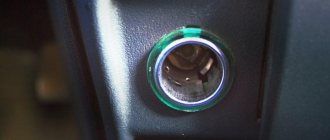
The most common way to use a cigarette lighter is obvious. It is an excellent way to light a cigarette and, if the driver does not have matches on hand, then a cigarette lighter will be a great help in this situation. But it is also useful for connecting various electrical devices that have a special connector. Their list is quite rich: a mobile phone charger, an electric kettle and much more. He will also be able to provide work for an entire car wash.
VAZ 2110 2111 2112 (injector) fuses and relays
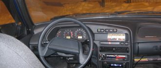
VAZ 2110 2111 2112 (Lada 110 111 112) - a family of cars produced in 1995, 1996, 1997, 1998, 1999, 2000, 2001, 2002, 2003, 2004, 2005, 2006, 2007, 2008 and 2009 with sedan and hatchback bodies and a station wagon mainly with 8 and 16 valve gasoline engines ( injector , carburetor). In this article you will find a description of the fuse and relay blocks of the VAZ 2110 2111 2112 with diagrams , photographs and their locations. Electrical connection diagram. Let's highlight the fuse responsible for the cigarette lighter.
The purpose of fuses and relays in your VAZ 2110 (2111 / 2112) relay may differ from those presented and depend on the year of manufacture. The current purpose can be printed on the block itself.
The relationship between a car lighter and a radio in VAZ cars
A common problem for all VAZ car models (2114,2115, 2109, 2110, 21099), this is the same voltage supply circuit to the car player, with output to one common fuse, which is additionally responsible for the power supply:
- cabin heater (stove);
- cigarette lighter;
- heated rear window;
- the radio itself.
Thus, a failure as a result of a break, short circuit, etc., in the electrical circuit of any device leads to the shutdown of the rest.
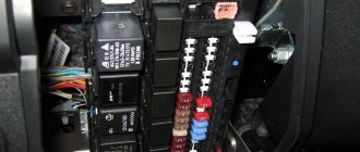
Main unit
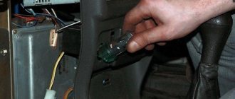
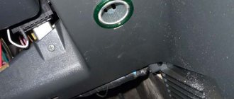
The main block with fuses and relays is located in the cabin, on the left side, under the control panel. To access, press the latch switch.
Photo - diagram Option 1
Scheme Option 2
Scheme Option 3
Description of fuses
p, blockquote 15,0,0,0,0 —>
| F1 | 5A Lamps for license plate lights. Instrument lighting lamps. Side light indicator lamp. Trunk light. Left side marker lamps |
| F2 | 7.5A Left headlight (low beam) |
| F3 | 10A Left headlight (high beam) |
| F4 | 10A Right fog lamp |
| F5 | 30A Electric motors for glass door lifts |
| F6 | 15A Portable lamp |
| F7 | 20A Electric motor of the engine cooling system fan. Sound signal |
| F8 | 20A Rear window heating element. Relay (contacts) for turning on the heated rear window |
| F9 | 20A Recirculation valve. Windshield, rear window and headlight cleaners and washers. Relay (coil) for turning on the rear window heating |
| F10 | 20A Reserve |
| F11 | 5A Starboard side marker lamps |
| F12 | 7.5A Right headlight (low beam) |
| F13 | 10A Right headlight (high beam). High beam warning lamp |
| F14 | 10A Left fog lamp |
| F15 | 20A Electric seat heating. Trunk lock lock |
| F16 | 10A Relay - turn signal and hazard warning light switch (in hazard warning mode). Hazard warning lamp |
| F17 | 7.5A Interior lighting lamp. Individual backlight lamp. Ignition switch illumination lamp. Stop lamps. Clock (or trip computer) |
| F18 | 25A Glove box lighting lamp. Heater controller. Cigarette lighter. |
| F19 | 10A Door locking. Relay for monitoring the health of brake light lamps and side lights. Direction indicators with warning lamps. Reversing lamps. Generator excitation winding. On-board control system display unit. Instrument cluster. Clock (or trip computer) |
| F20 | 7.5A Rear fog lamps |
Fuse number 18 at 25A is responsible for the operation of the cigarette lighter.
The fog lamp fuse is installed separately in the instrument panel niche behind the main unit.
Relay purpose
p, blockquote 19,0,0,0,0 —>
- K1 - lamp health monitoring relay
- K2 - windshield wiper relay
- KZ - relay-breaker for direction indicators and hazard warning lights
- K4 - relay for low beam headlights
- K5 - headlight high beam relay
- K6 - additional relay
- K7 - rear window heating relay
- K8 - rear fog lamp relay
Electrical diagram of the block
Additional block
It is located under the center console and is covered with a lid. One part is accessible from the right side.
Designation
p, blockquote 27,0,0,0,0 —>
- 15A - Ignition module, controller
- 15A - Canister purge valve, vehicle speed sensor, oxygen concentration sensor (heating), air flow sensor
- 15A - fuel pump, fuel pump fuse, injectors
- Electric fan relay
- Fuel pump relay
- Main relay (ignition relay)
The other part is on the left side of the console:
Decoding
p, blockquote 31,0,0,0,0 —>
- Central locking control unit
- Immobilizer block
- Relay for turning on rear fog lights.
On our channel we also prepared a video on this publication. Watch and subscribe.
p, blockquote 33,0,0,0,0 —> p, blockquote 34,0,0,0,1 —>
Do you know how to make the material better? Write in the comments.
Source
Where is the fuse for the VAZ-2110 radio?
Fuse links are installed in the wiring of passenger cars to protect the equipment from short circuits. The fuse for the VAZ-2110 radio ensures normal operation of the head unit and related components. When installing an additional active-type subwoofer or amplifier, it is recommended to connect separate protective elements in the power supply circuits of the devices.
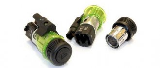
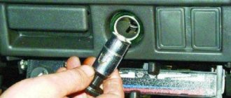
Inspection of cigarette lighter wiring
If after replacement the protective element burns out again, you should look for the cause elsewhere.
It lies not in the VAZ cigarette lighter fuse, but in faulty wiring. If the car is old or due to improper manipulation of the electrical system, the wires may shorten and burn out, or an open circuit may occur in the circuit itself, causing the cigarette lighter fuse to trip. It is advisable to inspect the cables for kinks or abrasions. This failure should be diagnosed using a multitester. The wires coming to the cigarette lighter are tested for resistance. If there is no power, then one of the cables is broken.
To repair the cigarette lighter on a VAZ, you will need a soldering iron with rosin and tin, working cables and insulating tape.
Functions
A blade-type fuse is a wire designed to carry a certain amount of current. If the parameter is exceeded, part of the element is heated and melted, which allows the power circuit to be broken.
To install the part in the mounting block, flat rectangular legs are used, which are clamped with spring contacts. Metal parts are placed in a plastic case; the color of the material depends on the product rating. The body is transparent, which allows you to visually assess the condition of the fuse thread.
Where is
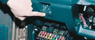
The fuses located in the instrument panel to the left of the steering column casing are responsible for protecting the power circuits on VAZ-2110 cars. The top of the unit is closed with a decorative cover, which is secured with a spring clip. To access the fusible links and relays, you need to press the button located under the rotary control for the headlight range control. The decorative casing folds down along with the mounting plate and the protective and distribution devices. On VAZ-2112 and 2111 cars, blocks are used that differ in the number and location of the relays.
Also inside the mounting block are special plastic tweezers and spare inserts. To replace the fuse, the part should be grabbed tightly with tweezers and then carefully pulled out of the socket. The new part must have an identical value; the use of homemade inserts made of wire or foil is strictly prohibited.
The use of fuses designed for high current strength is not allowed, as this may cause the wiring to heat up and the vehicle to catch fire.
Since the cars of the “tenth” family were not equipped with a standard head unit, the installation of radio tape recorders was carried out at dealership centers or by the owners themselves. Since the head acoustic device is a consumer of electric current up to 10-15 A, it is switched through the most powerful fuse. In most cases, this was done using a fuse link designed to protect the cigarette lighter circuit and heater controller. The device has a rating of 25 A, located in the bottom row in the third position from the right.
This switching scheme speeds up installation, but is not correct, since there is a risk of overloading the radio or burning out the insert due to the simultaneously operating head unit and cigarette lighter. It is recommended to connect the radio directly to the battery; a 10-15 A fuse is located inside the power cable.
To protect the battery from discharge, the circuit passes through the ignition switch; a cord with red insulation is used for switching.
When the engine is turned off, the radio does not work, but voltage is supplied (through a yellow insulated cable) to save the settings.
The head unit contains a blade-type fuse rated at 5-15 A (depending on the equipment modification). The element is placed either next to the ISO standard connection block, or inside the wiring harness that comes with the radio. To replace an element, you need a player from a standard socket; for this, special hooks are used that press out the spring clamps.
After installing a new element, it is recommended to check the functionality of all devices involved in the circuit section. If the fuse blows again, the cause of the malfunction is a short circuit in the electrical wiring or inside the head unit. A tester is used to check the condition of the wires; it is recommended to send the radio to a service center for diagnostics and repair.
Connecting a radio via an additional button
To prevent current leakage, place a button in the cut of the red wire:
- Button in the section of the red wire of the radio;
- The button switches between constant “plus” and after ignition;
- Through the alarm.
With the first option, I think everything is clear: just a regular on/off button is hung in the cut of the red wire on the radio. Thus, your radio always works, but if you decide to leave the car in the parking lot for a long time, then simply turn it off. button to supply current to the radio.
The second option is when an emergency button is used instead of a regular button. You will use the second emergency button to switch the power mode of the radio:
- The button is pressed - power is supplied to the radio through a constant plus
- The button is not pressed - power is supplied to the radio through the plus from the ignition
Example of connecting a car radio:
- The radio backlight wire to the cigarette lighter backlight wire.
- Plus after ignition from the clock block (orange wire)
- A permanent plus with a battery or cigarette lighter.
- Ground "-" from the cigarette lighter
Third option: you can install a simple circuit that will supply a plus and automatically disconnect it from the alarm.
If the car has a two-wire solenoid with activation for closing and opening by changing the polarity for each of these operations, then it should work like this: When the doors are opened, a positive pulse from the solenoid is sent to relay P1, and the relay will operate and actually go into self-retaining mode, providing power from the battery through the terminals of its contacts and relay P2 and connecting the radio to the power supply.
If there is a positive pulse during closing, relay P2 will be triggered, and the power supply circuit of relay P1 and the radio will break, the radio will turn off, and the relay will go into a de-energized state. But this scheme also has a minus - it is increased power consumption due to the additional relay P1, which will always be turned on along with a working radio.
Fuse box for VAZ 2110, location diagram, description LuxVAZ
In cars, a fusible type of fuses is installed. That is, devices that burn out as a result of short circuits and similar accidents. How to interrupt a contact connection on a certain section of electrical wiring. In terms of the power they can withstand emergency loads, safety devices differ in their rated voltage, as indicated by their markings and a duplicate inscription near the connector socket intended for its installation.
In Soviet-made cars, cylindrical fuses were installed, which were very unreliable in operation and quite unsafe due to their technical design. Today, in all VAZ products without exception (VAZ 2110, VAZ 2114, Priora, Kalina, etc.), as well as in foreign-made cars (Ford, Audi, etc.), blade fuses are used. More advanced in their design and aesthetics, devoid of the disadvantages inherent in their predecessors, cylindrical fuses.
Some tips
I recommend taking advantage of the opportunity while everything is sorted and carrying out some simple procedures to improve quality. These tips may seem trivial to you, but they will help extend the life of the new audio system for an extra year or two. First, tin the wires and solder them.
This procedure will prevent the sound from losing quality even during prolonged use. Use female/male connectors. This method will be more effective and easier than soldering. Use heat shrink tubing. They will help maintain the quality of wire connections and extend the time it takes to resolder.
Fuse layout diagram for VAZ 2110, 2111, 2112
Many owners of VAZ cars are familiar with the situation when the cigarette lighter suddenly stops working, the turn signal does not respond to being turned on, and the windshield wiper blades stop cleaning the glass. Many people then immediately run to the store for a new part, making an incorrect diagnosis. Most likely the problem is a blown fuse. These parts protect the wiring of our car from burning out.
Let's take a closer look at the fuse diagram for the VAZ 2110, 2111, 2112. The first VAZ fuse block is located in a special niche, to the left of the steering wheel.
How are the blocks separated in the machine?
The main type of block is placed in the most convenient place for the driver. In this version of the VAZ it is located on the left side of the body directly at the steering wheel. Easy access to the unit is provided using a built-in button located next to the car's headlight control.
2 backup units with relays are located separately in the right and central parts of the console just behind the dashboard. One of the fuses shown below in the diagram will be located at a distance from the rest of the list - it can be found in a special compartment behind the main fuse block, next to the mounting block. To timely repair electrical equipment on a VAZ-2110, you need to learn how to quickly determine the location of a blown fuse, and also know which elements of the car its failure will affect.
Advice: very often one burnt valve can lead to replacing the vacuum booster on a VAZ-2110. That is why it is important to check not only the general condition of the fuse, but also the parts that interact with it, for example, the injector.
Where is the fuse for the radio?
The fuse responsible for the radio is located in the power circuit. If the head unit is connected through the cigarette lighter cables, then the safety insert of the blade type or cylindrical configuration is located in the installation box inside the instrument panel. The distribution panel is located on the side of the steering column, under the hinged plug. On some machines, the inserts are mounted on a panel covered by the panel's end cover. Analysis of the electrical diagram pasted on the cover will allow you to find the desired insert.
The fuse for the radio is placed in the power cable, which comes from the battery terminal. The cassette-type insert has a rating of up to 50 A (depending on the power of the connected acoustic components), and is located at a distance of 400-500 mm from the power source. The upper part of the assembly is made of transparent plastic, which allows you to visually check the condition of the fusible element.
The design of the radio has an individual protective element responsible for protecting the electronics. A knife-type insert with a rating of 5-15 A (depending on the power of the amplifier and the total power consumption of the head unit) is inserted into the socket near the ISO switching connector. A similar element is used in standard radios.
How to find and replace a fuse on a radio
In cars, a fusible type of fuses is installed. That is, devices that burn out as a result of short circuits and similar accidents. How to interrupt a contact connection on a certain section of electrical wiring. In terms of the power they can withstand emergency loads, safety devices differ in their rated voltage, as indicated by their markings and a duplicate inscription near the connector socket intended for its installation.
In Soviet-made cars, cylindrical fuses were installed, which were very unreliable in operation and quite unsafe due to their technical design. Today, in all VAZ products without exception (VAZ 2110, VAZ 2114, Priora, Kalina, etc.), as well as in foreign-made cars (Ford, Audi, etc.), blade fuses are used. More advanced in their design and aesthetics, devoid of the disadvantages inherent in their predecessors, cylindrical fuses.
Which fuse is responsible for the cigarette lighter of the VAZ 2110
If the cigarette lighter of a VAZ 2110 car malfunctions, you need to open the main panel, which is located in the lower left part of the dashboard. There is a VAZ 2110 cigarette lighter fuse. It is marked F 18 and can withstand loads of up to 25A.
To replace it, you should use special tweezers. Under no circumstances should you remove the element with your fingers - this may damage the mounting sockets.
Where is the fuse for the radio?
The fuse responsible for the radio is located in the power circuit. If the head unit is connected through the cigarette lighter cables, then the safety insert of the blade type or cylindrical configuration is located in the installation box inside the instrument panel. The distribution panel is located on the side of the steering column, under the hinged plug. On some machines, the inserts are mounted on a panel covered by the panel's end cover. Analysis of the electrical diagram pasted on the cover will allow you to find the desired insert.
The fuse for the radio is placed in the power cable, which comes from the battery terminal. The cassette-type insert has a rating of up to 50 A (depending on the power of the connected acoustic components), and is located at a distance of 400-500 mm from the power source. The upper part of the assembly is made of transparent plastic, which allows you to visually check the condition of the fusible element.
The design of the radio has an individual protective element responsible for protecting the electronics. A knife-type insert with a rating of 5-15 A (depending on the power of the amplifier and the total power consumption of the head unit) is inserted into the socket near the ISO switching connector. A similar element is used in standard radios.
Additional fuses: 1 – ignition module, controller; 2 – canister purge valve, vehicle speed sensor, oxygen (heating) sensor, air flow sensor; 3 – fuel pump relay, fuel pump, injectors.
Additional relays: 4 – electric fan relay; 5 – electric fuel pump relay; 6 – main relay (ignition relay).
There is a fog lamp fuse installed in the niche of the instrument panel behind the mounting block:
Functions
The fuse of the radio, located in the power circuit, is designed to protect the electronic components of the equipment from the consequences of short circuits. The device is a thin thread of low-melting metal, designed to carry a certain current value. As the value increases, the element heats up and subsequently melts. The process takes place in a short time, which allows you to maintain the player’s electronics and the insulation of power cables in good condition.
The thread is soldered to the legs, all elements are housed in a transparent plastic case. The color of the plastic allows you to determine the rating of the fuse link; the digital value is applied to the end part with white or black paint. A fuse of this type is called a blade fuse and is installed in the mounting block in spring contacts that protect the product from falling out.
Trouble-shooting
Having established the reason why the VAZ cigarette lighter and radio are not working, we correct the detected breakdown. The list is given in accordance with the listed faults.
- We remove the fuse box (the hatch on the left side of the steering column of the car). We remove the device marked F4 (20 ampere fuse), test it for serviceability with a simple screwdriver probe, if this moment is not visually determined. And we replace it with a new one from the mandatory kit for such cases.
- Check the conductivity of the contacts with a probe. If they are loose, tighten them.
- Strip or resolder the contacts, depending on the situation.
Paradoxically, a burnt-out light bulb breaks the contact circuit (a kind of fuse). Replace it with a working one of the same power.
A short circuit most often occurs due to a loose cigarette lighter socket and a malfunction of its heating coil. If you have the opportunity, then replace them with new ones or restore them to proper condition.
How to connect
Connecting a car radio is carried out in stages:
- choosing a suitable connector;
- determining the connection method;
- connecting wires;
- housing installation.
Connector selection
For the VAZ radio, different connectors are selected:
- simple configuration;
- ISO type or international standard designs.
Simple connectors are universal, can be quickly installed, and require the use of a plug.
International format designs require the development of a special circuit for the connector. During installation, heat-shrinkable tubes can be used to comply with safety requirements.
We carry out plus
When connecting a car radio, it is important to route the positive wire correctly. The diameter of the wiring must match the radio connector
The diameter of the wiring must match the radio connector.
The positive connection is carried out according to the standard scheme, taking into account the following rules:
- The black wire needs to be grounded.
- The yellow wire is connected to the battery to create a power supply of 12 W.
- The red wire is required to connect the device to start from the ignition device.
- The blue wire is intended for connecting an antenna or other equipment.
- In the process it is necessary to use standard or low-current diodes.
Easy connection without button
You can connect the VAZ-2110 radio without a button by following the steps indicated in the instructions:
- It is required to apply a plus to the yellow wires (they regulate the power supply to the device’s memory) and the red wire (controls the radio turning off).
- To automatically turn off the car radio after stopping the ignition, you need to pass a red wire through the lock structure.
- In a VAZ-2110 model car, you can run networks to the contact of the block.
Correct connection with button
The button connection method ensures stable operation of the device. When stopping the car for a long time, it is necessary to turn off the current transmission.
You can correctly connect the radio in a VAZ-2110 car with a button by following these steps:
- The red wire is connected to the button through the connector. Then a standard button is hung.
- You can connect a button that allows switching between poles after ignition. In this case, the button reporting an emergency will be activated.
- You can connect the car radio through the alarm system. The standard method involves applying a pole that automatically disconnects the alarm.
For a car that has a two-wire solenoid that is triggered to open or close the doors and changes polarity at the stage of sequential operations, the radio is installed in a different way. Plus must be fed to a relay, which starts and operates in automatic picking up mode. In this way, constant power supply is ensured.
The car radio gets the ability to start in automatic mode. It must be taken into account that the implementation of this connection scheme ensures high power consumption due to the use of an additional relay.
Installation of the car radio is carried out in the following sequence of actions:
- It is necessary to remove the cover under the clock and route computer equipment.
- The metal body of the device is inserted into the rectangular window, which is fixed using triangular-shaped tabs.
- Then the antenna and power connectors are connected to the main device using adapters or directly.
- The housing must be installed in the mounting channel before the latches engage.
- Finally, the correct operation of the equipment is checked and decorative polymer plates are installed.
When operating a technical device, it is important to monitor current leakage due to the installation of an additional device. The allowed minimum current loss reaches about 50-80 mA
If the indicator is exceeded, it is necessary to inspect and repair the equipment.
- How to connect a car radio to a power supply from a computer
- ISO connector
- Do-it-yourself installation and connection of a radio on a Lada Vesta
- Instructions on how to connect the Mystery radio and wiring diagram
Functions
The fuse of the radio, located in the power circuit, is designed to protect the electronic components of the equipment from the consequences of short circuits. The device is a thin thread of low-melting metal, designed to carry a certain current value. As the value increases, the element heats up and subsequently melts. The process takes place in a short time, which allows you to maintain the player’s electronics and the insulation of power cables in good condition.
The thread is soldered to the legs, all elements are housed in a transparent plastic case. The color of the plastic allows you to determine the rating of the fuse link; the digital value is applied to the end part with white or black paint. A fuse of this type is called a blade fuse and is installed in the mounting block in spring contacts that protect the product from falling out.
Trouble-shooting
Having established the reason why the VAZ cigarette lighter and radio are not working, we correct the detected breakdown. The list is given in accordance with the listed faults.
- We remove the fuse box (the hatch on the left side of the steering column of the car). We remove the device marked F4 (20 ampere fuse), test it for serviceability with a simple screwdriver probe, if this moment is not visually determined. And we replace it with a new one from the mandatory kit for such cases.
- Check the conductivity of the contacts with a probe. If they are loose, tighten them.
- Strip or resolder the contacts, depending on the situation.
Paradoxically, a burnt-out light bulb breaks the contact circuit (a kind of fuse). Replace it with a working one of the same power.
A short circuit most often occurs due to a loose cigarette lighter socket and a malfunction of its heating coil. If you have the opportunity, then replace them with new ones or restore them to proper condition.
Expert advice
Professional automotive electrical repair technicians complain that even when carrying out repairs that are so insignificant in scope and complexity on their own. Some car owners manage to violate basic rules, thereby significantly aggravating the problem and transferring it to another, more complex (and expensive) repair category.
How to check current leakage
Checking current leakage
As you know, any car, including the VAZ 2110, has a minimum leakage current. It is about 50-80 mA. So:
- The alarm consumes about 20 mA.
- Injection system controller - 5 mA.
- Car radio - about 3 mA.
As a rule, such leaks are considered normal and the battery in this case can last for several years without letting the vehicle owner down.
Note. If the leak exceeds 80 mA, it’s time to sound the alarm and look for the cause.
Leakage current measurement
In our article we will not dwell in detail on measuring leakage, but will provide only general recommendations on how and what to do. Basically, everything will concern the car radio:
- Set the multimeter to 10/20 Ampere mode.
- We stick the black probe into the COM hole.
- Red probe in hole 10
Note. To check, it is recommended to remove the battery from the TV remote control and measure the short-circuit current. It is prohibited to measure short-circuit current on the battery itself!
- Go ahead and remove the terminal from the battery.
- We connect one of the wires of the device to the battery.
- Another probe is placed on the wire removed from the battery.
- We look at the value and determine.
Note. If the leakage current comes from the car radio, then most likely the value will be 520 mA.
A simple rectifier on a step-down transformer from a 220 V network
The implementation of this option is more difficult, but for those who love to tinker, it will not be difficult. We won’t tell you how to wind a transformer. We assume that you already have it and with the necessary parameters. Namely:
- input voltage 220–230 V, output - 12 V;
- power - from 120 watts depending on the audio system;
- current up to 10 A.
At its output we will have 12 V AC, and the car radio is powered by DC. Therefore, this tension must be straightened. You can assemble an elementary circuit using a diode bridge and a capacitor.
Diodes, for example, KD226, it is better to set the capacitor at 4700 μF to reduce ripple. Before connecting, check the output voltage parameters. Without load it can be slightly higher and amount to 14 - 15 volts.
How to remove and replace the relay and fuse mounting block on a Lada Priora
But there are often cases when it is simply not possible to replace one relay and fuse. In this case, you have to replace the entire mounting block. For this:
- Disconnect the minus terminal from the battery
- Removing the cover of the mounting block
- We unscrew the screw securing the mounting block to the instrument panel
- We remove the mounting block from the instrument panel, disengaging it from the mounting hooks.
- Remove all relays and fuses from the mounting block
- We press out the clamps of the electrical wiring terminals
- We remove the terminals with wires from the mounting block and remove the mounting block from the car
Car radio 2 din class
More and more car enthusiasts who value comfort and convenience have begun to consider the option of equipping the VAZ 2112 with 2 din radios. It is distinguished from classic models by:
- Dimensions – 17.8 x 5.0 x 18.0 cm.
- Availability of a tuner for playing CDs.
- USB input for reading information from a flash drive
- Ability to play DVD files.
- Input for connecting and viewing information from a video camera, navigator and recorder.
- LCD liquid crystal touch screen.
The ability to connect to the driver’s cell phone via Bluetooth allows you to make/receive hands-free calls. The navigator helps you accurately plot your route.
Car radio 2 din
The procedure is:
Step-by-step installation of a Lada Granta radio: how to install it yourself in standard, normal and luxury
- Installation of the radio shaft.
- Power connection.
- Connecting the connector to the speaker wires.
- Connecting a video camera.
- Installation of the radio itself in the shaft and fastening with a snap frame.
Polarity must be observed when making connections. The wiring is pink - positive, black - negative (ground). If the connection is incorrect, the fuse may blow. If the radio does not work after connecting, you should check its serviceability and, if necessary, replace it with a new one after reversing the polarity.
Location
Since AvtoVAZ engineers tried to do everything so that car owners would not have problems replacing relays and fuses, it would be stupid to come up with a clever arrangement. Therefore, finding them is not difficult.
- The main unit is located to the left of the steering wheel;
- You will find the first additional block in the dashboard inside the niche, directly behind the main mounting block;
- The second additional block is located in the same place, only on the opposite side.
We will get acquainted with each block separately so that you do not have any confusion when searching for one or another fuse.
On injection engines with 16 and 8 valves, the location of the MB is identical, so the instructions are equally relevant for owners of both versions of the dozen.
Main MB
Relays and fuses are located here. Let's look at their descriptions in more detail and separately.
Found the main MB
Let's start with the relay.
| Designation | What is he responsible for? |
| K1 | Car lamp operation |
| K2 | Electric windshield wipers |
| K3 | Special relay that interrupts the turning lights when the hazard warning lights are activated |
| K4 | Turning on the low beam |
| K5 | Turning on the high beam |
| K6 | Area for installation of additional device |
| K7 | Rear window heating operation |
Fuse diagram
Next comes the fuses. They are located in the same place, but are designated by the letters F.
Each fuse is indicated with a current rating and designation. This allows you to use a new fuse with parameters that meet the requirements of the equipment connected to it.
| Designation | Rated current | What is he responsible for? |
| F1 | 5A | Lamps for license plate illumination, instrument panel illumination, indicator lights on the instrument panel, left side position lights, luggage compartment illumination |
| F2 | 7.5A | Low beam left headlight |
| F3 | 10A | Left high beam |
| F4 | 10A | Right front fog lamp |
| F5 | 30A | Electric door windows |
| F6 | 15A | Carrying lamp, cigarette lighter |
| F7 | 20A | Radiator fan, horn (horn) |
| F8 | 20A | Heated rear window |
| F9 | 20A | Windshield wipers and washer |
| F10 | 20A | Backup fuse |
| F11 | 5A | Right dimensions |
| F12 | 7.5A | Low beams in the right headlight |
| F13 | 10A | High beams in the right headlight |
| F14 | 10A | Left fog lamp |
| F15 | 20A | Heated seats in the cabin |
| F16 | 10A | Hazard signal, turn signals |
| F17 | 7.5A | Stop signal, ignition switch illumination, interior lighting |
| F18 | 25A | Interior heater, glove compartment light, cigarette lighter |
| F19 | 10A | Reversing light, brake light monitoring |
| F20 | 7.5A | Rear fog lights |
First additional block
Inside the central panel there is the first of two additional blocks provided for the VAZ 2110. You can find it at the bottom left on the front passenger side.
This block provides three fuses. Each of them has the same power rating - 15A.
- The first fuse is responsible for your vehicle's ignition and controller module.
- The second protects the mass air flow sensor, heating sensor, speed sensor and purge valve.
- The third is necessary to ensure protection of the injectors, as well as the fuel pump. So if problems arise with the fuel pump, the first thing we recommend is to check the condition of the fuse responsible for it.
Location of the additional block
Plus, the same block includes three relays:
- Relay number 4 is responsible for the electric fan;
- Relay number five is the electric fuel pump;
- The third relay is part of the ignition protection group on your VAZ 2110.
Second additional block
The second additional block should be looked for already in the driver’s feet, on the right. Behind the protective cover on the console you will find the required board.
There are three more components on it. They are responsible for:
- Immobilizer operation;
- Additional optics (mostly fog lights);
- For the operation of the car's central locking control.
Replacing the cigarette lighter fuse
It would seem that what’s wrong with replacing the fuse, I pulled it out and inserted a new one. But no. Here is the correct procedure for replacing a fuse:
- Turn off the car ignition.
- Disconnect the ground from the car battery.
- Carefully remove the blown fuse using special pliers. If they are not there, then use pliers (pliers).
- The new fuse must be installed so that it is designed for the same current strength that was on the old blown fuse. For example, on the PCB it says 20, which means that it can withstand up to 20 Amperes. If you install a more powerful one, then the fuse will be able to withstand load surges, but the cigarette lighter itself may burn out. The fuse can be inserted from either side.
- An old burnt-out fuse will have a burnt-out thread; you can look and find out whether it is the cause of the cigarette lighter failure. It also happens that the cause may not be a PP, but a broken wire. If the fuse is intact, you need to test the wiring with a multimeter.
- Close the block cover.
- We connect the disconnected negative wire back to the battery terminal.
- Turn on the ignition and check the functionality of the cigarette lighter.