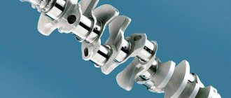
A modern engine is a very complex device consisting of a large number of parts. One of the most important is the crankshaft and all the parts associated with it, which transmit the energy of combustion fuel to the wheels, giving them rotation. An integral part of the crankshaft are the main and connecting rod bearings, which are the first to move during engine operation.
How to choose
Regardless of the reason for repairing the engine and replacing the liners, boring the crankshaft is a must. Installation of new parts is only possible on a polished or new mechanism. If there is damage and potholes on only one neck, all elements are processed to achieve a single overall size. Standard parts are installed during the engine assembly line. For example, repair crankshaft liners for VAZ cars are sold in four versions. That is, boring can be done a maximum of four times. Motors for cars such as Moskvich and GAZ have an additional fifth and sixth grinding of up to 1.5 and 1.2 mm, respectively. The best option would be for the person who did the grinding to select the required sizes. Boring may lead to the need to select elements whose size will significantly exceed the previous one. This depends on the depth of the potholes on the necks and their number. The inserts are sold as sets for both types of necks.
Conclusion
The crankshaft is considered an important and very expensive part of the car, which operates under incredibly heavy loads. Therefore, it is important to do everything to extend its service life. A timely measure would be to bore the shaft and properly replace the liners. All this will help make the elements of the mechanism smoother and stronger, so that they are ready for work almost immediately.
Inserts can be purchased separately or as a set. An important point here is that for each car there are standard inserts that help in the future to select elements with similar characteristics. Successful operation of the crankshaft and the car as a whole!
What are crankshaft bearings?
Connecting rod systems The
crankshaft bearings are the plain bearings for the connecting rods that rotate the shaft. The rotation here is a consequence of a microscopic explosion occurring in the combustion chambers of the engine cylinders.
The high speed and heavy loads that arise in this system force the friction of the parts between each other to be minimal, otherwise the engine will fail almost instantly. And this absolutely cannot be allowed. What helps protect the engine?
To prevent this from happening, important engine parts have a thin oil film, which is provided by a special lubrication system of the automobile engine. The appearance of such protection is possible only with fairly high oil pressure
That is, the crankshaft liner parts provide some protection, extending the life of such an important part.
There are connecting rod and main crankshaft bearings. The first are located between its connecting rods and journals. The main ones have a similar role, but their location corresponds to the space between the crankshaft and its passage through the housing of the internal combustion engine.
Features of operation
During engine operation, the liners are subject to constant loads due to mutual friction of these parts. Therefore, the installation of the main bearings must be carried out with reliable fixation to avoid their displacement by the rotating crankshaft. To achieve this, measures are taken:
- Firstly, they take into account the characteristics of friction of the parts in question, which manifests itself when they slide against each other under load. Its value is determined by the friction coefficient and the magnitude of the load on the interacting parts. Therefore, to ensure reliable retention of the liners, the impact of the crankshaft on them should be reduced. For this purpose, the coefficient of friction is reduced by using antifriction materials that are applied to the surface of the liners.
- Secondly, the main liners are mechanically held in place. Two methods are used for this. These elements are installed with interference specified structurally. In addition, on each of them there is an additional element called a tendril, which also serves for holding.
You need to know the dimensional parameters in order to ensure proper interference and correctly install the main bearings. The dimensions of these elements are selected based on the diameter of the bed. According to this parameter, the liners are divided into size groups, the designation of which is contained in the marking.
Based on size, crankshaft main liners are divided into nominal and repair. There are four repair sizes with a difference of 0.25 mm. They are used if replacement is carried out for a ground crankshaft in accordance with its dimensions.
Crankshaft bearing design
What is an engine crankshaft in a car?
The crankshaft sliding bearing is a composite bearing, containing two metal flat half-rings that completely enclose the crankshaft journal (top and bottom). This part performs several elements:
• Holes (one or two) for passing oil into the oil channels in the crankshaft and connecting rod; • Locks in the form of tenons or grooves for pins for fixing the bearing in the crankshaft bed support or in the lower head of the connecting rod; • Longitudinal groove for supplying oil to the hole (performed only on the liner located on the side of the channel - these are the lower main liner and the upper connecting rod liner); • In shoulder thrust bearings there are side walls (collars) for fixing the bearing and limiting the axial movement of the crankshaft.
The liner is a multilayer structure, the basis of which is a steel plate with an anti-friction coating applied to its working surface. It is this coating that ensures reduced friction and long service life of the bearing; it is made of soft materials and, in turn, can also be multi-layered. The coating of the liner, due to its less softness, absorbs microscopic wear particles from the crankshaft, prevents jamming of parts, the formation of scuffing, etc.
According to their design, crankshaft liners are divided into two main groups:
• Bimetallic; • Trimetallic.
Bimetallic bearings have the simplest design. They are based on a steel strip 0.9-4 mm thick (depending on the type and purpose of the part, main bearings are thicker, connecting rod bearings are thinner), on which an anti-friction layer 0.25-0.4 mm thick is applied. This layer is made of copper-lead-tin (bronze), copper-aluminum, copper-aluminum-tin, aluminum-silicon-lead, aluminum-silicon-lead-tin or other soft alloys with an aluminum and copper content of up to 75%, and tin (which acts as a solid lubricant) up to 25%, may also contain small amounts of nickel, cadmium, zinc and other metals.
Trimetallic liners, in addition to the main antifriction coating, have a coating layer 0.012-0.025 mm thick (12-25 microns), which provides protective properties (fights corrosion and excessive wear of the main layer) and improves the antifriction qualities of the bearing. This coating is made from a lead-tin-copper alloy with a lead content of 92-100%, tin up to 12% and copper not more than 3%.
Also, additional layers may be present in sliding bearings:
• The top protective layer of tin is a pure tin coating with a thickness of only 0.5-1 microns, providing protection against corrosion, grease and contamination during transportation, installation and running-in of the liner; • Bottom protective layer of tin - the same layer applied to the outside of the liner (facing the crankshaft supports or the inside of the connecting rod head); • Nickel sublayer (nickel barrier, gasket) - a thin, no more than 1-2 micron layer of nickel between the main anti-friction coating and the cover layer. This layer prevents the diffusion of tin atoms from the coating layer into the main one, which ensures the constancy of the chemical composition of the main antifriction coating. In the absence of a nickel barrier in the base coating, the concentration of tin may increase, which leads to negative changes in the characteristics of the bearing.
The considered structure of sliding bearings is not a standard; many manufacturers offer their own unique schemes and designs. For example, the main antifriction alloy can be applied to the steel base not directly, but through an additional sublayer of aluminum or copper alloy; the coating layer can have a varied composition, including lead-free, etc.
Liner - crankshaft
| Checking the diametrical clearance in the crankshaft bearing.| Diagram for replacing the upper main bearing shell.| Restoring worn parts by installing bushings. |
Communities Diesel Power Diesel internal combustion engines Blog Replacing main bearings without removing the crankshaft Lifehack
The crankshaft bearings can be replaced while the vehicle is in use, without removing the shaft. Replacement is carried out without any additional adjustment and only in pairs.
The crankshaft liners of carburetor engines allow one boring to the repair or nominal size on high-precision machines of the Odessa Machine Tool Plant. When this possibility has been exhausted, galvanic coatings are applied to the working surfaces of steel-aluminum liners made of AO-20-1 or AO-6 material.
| Checking the diametrical clearance c. |
Replacement of the crankshaft liners is carried out when the bearings are knocking and the pressure in the oil line drops below 0 5 kgf / cm2 at a crankshaft speed of 500 - 600 rpm and the oil pump and pressure reducing valves are working properly. The need to replace the liners is due to the diametrical clearance in the main and connecting rod bearings; if it is more than acceptable, the liners are replaced with new ones. The nominal clearance between the liners and the main journal should be 0 026 - 0 12 mm, between the liners and the crankpin 0 026 - 0 П mm, depending on the engine model.
| Scheme of installing an elastic DRM on the shaft journal. |
To avoid damage to the crankshaft liners when the engine is running, it is necessary to carefully remove burrs from the tape, maintain the angle between its petals, their length and the depth of the flats on the shaft journal.
It is known that the current trend in the production of crankshaft liners is the use of a third soft layer, which serves to speed up and improve running-in. For this purpose, for example, lead-tin alloys are used. Covered with microcavities, possessing high oil absorption and wearability, the self-alloying surface with a large actual contact area represents a kind of third layer. Its feature is high manufacturability and the absence of an interface with the main antifriction layer, which guarantees relatively higher fatigue strength regardless of the near-surface hardness formed during the factory running-in process.
Currently, lead bronze, SOS-6-6 alloy, etc. are used as the antifriction layer of crankshaft liners. These materials have greater strength, hardness and heat resistance than tin babbitts. Their disadvantage is their high tendency to corrosion, due to their high lead content. The composition and structure of the alloy largely determine its susceptibility to corrosion.
The frame is installed on the foundation, the crankshaft liners are placed on the wedges and alignment begins. First, the crankshaft axis is horizontal, checking it with a calibrated roller and a level (Fig. Next, the frame is aligned along the cylinder axis. The check is carried out with a level installed on the lower guide surface of the crosshead (Fig.
Modern high-performance engines place particularly high demands on the reliability of crankshaft liners. In this regard, Babbitt liners are unpromising; They are used mainly only on low-speed marine diesel engines with small loads on the crankshaft bearings.
The areas of use of aluminum bearing alloys in the Soviet Union are expanding every year. Crankshaft liners for a number of automobile engines are made from a strip with a layer of AO20-1 alloy. This strip is manufactured at the Zavolzhsky Motor Plant. In particular, positive results have been obtained from the use of such bearings in heavily loaded forced engines of ChTZ tractors.
The most favorable conditions for the formation of varnish are created in stagnant zones of surfaces, in particular in the grooves for rings and in areas of the side surface of the piston that have recesses; For these places, the presence of high temperature is not necessary. The formation of varnish was observed in the recesses made specifically on the antifriction layer of the crankshaft liners.
When the ambient temperature drops, the operation of diesel engines becomes much more difficult, since the viscosity of the oil increases greatly - it thickens and sometimes freezes. Oil thickens in the engine crankcase, oil filters, on the crankshaft journals and liners, in the gaps between the piston and the cylinder mirror and on other rubbing parts. This makes it difficult to start the engine, normal lubrication conditions are disrupted, and the wear of its parts sharply increases during the start-up period.
| Staggering and wear of the crankshaft main bearings. |
Description of crankshaft bearings
Buy a timing belt
All crankshaft main and connecting rod journals have their own dimensions; we are talking about the parameters that the journals take after the grinding process. The dimensions of these elements must fully correspond to the dimensions of the crankshaft repair liners. Accordingly, when purchasing such spare parts, you must take into account the parameters of your vehicle, because each individual engine has its own dimensions.
For example, if you own a classic VAZ car, you should keep in mind that domestic cars have four different sizes of liners. This means that the crankshaft can, in principle, be bored no more than four times. You also need to take into account that the crankshaft liners also have an outer size, which never changes, but the inner one can be adjusted due to an increase in the thickness of the elements.
Purpose of the inserts
In fact, the crankshaft main bearings, regardless of the markings, act as bearings designed to improve the sliding of the connecting rods. Connecting rods, as you know, are designed to rotate the crankshaft under the influence of a micro-explosion of the combustible mixture in the combustion chambers of the engine. Since the elements periodically wear out, the motorist must promptly remove and replace them, which should also be accompanied by boring the shaft.
It is no secret that when the engine is running, internal components are subjected to high loads and rotation speeds. This means that the motor simply needs to reduce friction, otherwise the unit may fail almost immediately. To ensure that the friction force is significantly lower, all the necessary components inside the motor operate in a micron film, which is oil.
This layer, which envelops the metal components of the unit, is formed only with sufficient pressure of the working fluid. In particular, the film should always be between the crankshaft journal and the liner, as a result of which the friction index is not as high as it could be. Accordingly, the liners, which are made of metal, provide reliable protection that allows you to increase the service life of the shaft as a whole.
Design
It would seem that the crankshaft liner is a common part, but its manufacture is carried out using several different metals.
Accordingly, the liner consists of several layers, which we will consider below:
- the first layer is made from copper, its percentage can be from 69 to 75%;
- the second layer is made from lead, its percentage ranges from 21 to 25%;
- third layer - tin, about 2-4%.
In general, the total thickness of the liner is 250-400 microns. It should be noted that sometimes not copper, tin and lead are used to make the liner, but a specialized aluminum alloy. Labeling in this case will depend solely on the manufacturer.
Kinds
As for the types, the marking here will depend on the type of component.
In general, crankshaft bearings are divided into several groups:
- Indigenous. Regardless of the marking, the main bearings perform similar functions. They are mounted between the crankshaft and the place where this shaft passes through the engine housing.
- Connecting rods. The connecting rod components are located directly between the connecting rods and the shaft journals.
In principle, bearings, both connecting rod and main, are produced for each type of engine, but they all differ in internal diameter. Depending on the engine model, the diameters of the elements will be different, even for the same engine. As a rule, the difference in diameter, that is, the pitch, is 0.25 mm. This means that the size range of parts is compiled as follows: 0.25 mm, 0.5 mm, 0.75 mm, etc.
As a result of wear of the shaft journals and liners, the diametrical clearances in the main and connecting rod bearings of the crankshaft increase, and cracks and chipped areas appear on the liners. This leads to bearing knocking, increases lubricant consumption and reduces oil pressure in the line, since lubricant flows freely from the ends of the bearings, and the performance of the oil pump is insufficient to maintain normal pressure.
The oil leaking from the bearings is captured by the rotating crankshaft and is thrown with force in all directions, especially onto the cylinder walls. The amount of oil entering the cylinder walls turns out to be so large that the pistons and piston rings cannot cope with the task of regulating the oil film on the cylinder walls and allow a significant amount of it to pass into the combustion chambers, where it burns. This increases lubricant consumption and carbon formation, reduces engine power and leads to detonation.
On the other hand, the grease that easily flows out of the bearings prevents the formation of an oil cushion between the shaft journal and the liner, and certain areas of their contacting surfaces remain dry. In this way, favorable conditions are created for increased wear of these parts, chipping and melting of the babbitt liners, as well as scuffing of the shaft journals.
In addition, over time, a large amount of engine wear products, circulating with lubricant, become embedded in the babbitt layer of the liners. Babbitt loses
its antifriction properties and begins to intensively wear out the surface of the shaft journals.
All this necessitates periodic replacement of liners. We must firmly remember that timely replacement of worn bearings with new ones of appropriate repair sizes, or even bearings of the same size as those being replaced, will extend the service life of the crankshaft and the engine as a whole.
The main and connecting rod bearing shells of the GAZ-51, ZIM-12, M-20 and GAZ-69 engines are replaced without any additional adjustment operations, which is ensured, firstly, by high accuracy! the manufacture of the liners themselves, the beds for them in the block and connecting rods, as well as the crankshaft journals, and, secondly, the fact that the outer diameter of the liners of all repair sizes is equal to the outer diameter of the liners of standard sizes (repair size liners of the same names differ from each other only internal diameter and wall thickness). Both shells of each bearing must be replaced at the same time: replacing only one bearing shell is not allowed. When changing liners, the following conditions must be carefully observed:
1. The fixing protrusions located at one of the joints of each liner must fit correctly into the grooves intended for them in the beds.
2. The halves of the main bearing shells, which have holes in the middle for the oil supply (upper), would be placed in the block bed, and the halves without holes (lower) would be placed in the cover bed. Otherwise, lubricant will not flow to the main bearing with incorrectly installed halves of the liners, as well as to the connecting rod bearings that this main bearing feeds, and the bearings, and together with the shaft journals, may immediately fail.
3. Immediately before assembly, the beds under the liners in the block and connecting rods, the backs of the liners and the shaft neck should be thoroughly blown with compressed air or wiped with a clean and dry cloth that does not leave lint behind.
The working surface of the liners should also be blown with compressed air or wiped with a clean and dry flannel cloth specially designated for this purpose.
It must be borne in mind that even a small amount of dirt trapped between the wall or working surface of the liner, impairing heat dissipation from the liner and reducing the oil clearance in the bearing, leads to chipping of the babbitt or even melting of it.
4. Lubricate the working surfaces of the shaft journals or bearings generously (pour from an oil can) with clean oil, poured into the engine crankcase.
After any replacement of the liners (with or without regrinding the journals), you should definitely check the diametrical clearance in each of the bearings in order to make sure that the regrinding of the shaft and the selection of the size of the repair liner were done correctly. You should especially be wary of excessively small gaps, because they, as a rule, are one of the main reasons for cracking, chipping and melting of babbitt.
The minimum clearance for both main and connecting rod bearings is 0.025 mm; gaps of more than 0.08 mm lead to bearing knocking; the optimal gap is a gap of 0.04-0.05 mm.
Checking clearances can be done in one of the following ways:
1. Direct measurements of the actual dimensions of the crankshaft journals and bearing beds in the connecting rods and block, as well as the wall thickness of the bearings, followed by calculation of the size of the gaps based on these measurements. 2. Using a set of control probes made of thin thick paper or copper foil with a thickness of 0.025, 0.05, 0.075, mm, etc., placed in the gap between the surfaces of the neck and the lid liner.
Paper probes are made with a width of 12-13 mm, and from copper foil - with a width of 6-7 mm. The length of the probes should be slightly less than the width of the liner.
The test consists of removing the cover from the bearing being tested and placing a paper probe of minimum thickness (0.025 mm) on the surface of its liner (Fig. 99) or the shaft journal with its larger side along the journal. After replacing the cover and tightening it, an attempt is made to rotate the shaft by hand using the counterweights; the cap bolts of the remaining bearings must be loosened. If the shaft rotates too easily, then the gap is greater than 0.025 mm. After this, the thickness of the feeler gauge increases successively until the shaft becomes impossible to rotate. The thickness of the feeler gauge at which the shaft still rotates, but with noticeable effort, is taken to be equal to the actual value of the gap in the bearing.
Checking the gap with copper foil probes differs from that described above only in that after tightening the cover, the shaft is not turned in a circle, but only 80-90°, so as not to damage the surface of the liner.
The edges of the copper probe, in order to avoid pressing the liners into the babbit, are cleaned with a whetstone; The dipstick itself is lubricated with oil before measurement.
When checking clearances with feeler gauges, it is recommended to tighten the main bearing bolts or connecting rod bolt nuts using controlled torque wrenches
tightening to obtain uniform and constant tightening of the caps. 3. The simplest and at the same time quite reliable is to check the clearances in the bearings “by touch”.
It is believed that with normal clearances, a connecting rod assembled on the shaft journal (without a piston) with a fully tightened cap should smoothly lower under the influence of its own weight from a position close to horizontal (approximately 45° before reaching it) to the lower vertical position or pass through it (to in case of faster lowering of the connecting rod), remaining in the position it occupies. With normal clearances in the main bearings, the crankshaft, with four caps fully tightened, but without connecting rods installed, should be turned by hand using two elbows without noticeable effort.
When checking “by touch”, the connecting rod and main journals must be lubricated with oil poured into the engine crankcase. The required diametrical clearance in the bearing must be ensured by the correct combination of the dimensions of the shaft journal diameter and the wall thickness of the liners.
It is strictly prohibited to saw off or scrape the joints at the bearing caps, as well as install gaskets between the liners and their beds to reduce clearances in the bearings, because:
1) in bearings with sawed off or scraped caps, subsequent installation of new liners (repair sizes) is impossible due to an increase in their tension in the beds, leading to deformation of the liners when tightening the covers and, as a consequence, to an excessive reduction or complete absence of the oil gap with all that it implies hence the consequences; sawn or scraped covers cannot be replaced with new ones, since they are processed together with the block or connecting rod and therefore are not given separately as spare parts - therefore, blocks or connecting rods with such covers are unsuitable for further use and must be discarded;
2) spacers between liners and beds reduce
the diameter of the latter, as a result of which, just as with sawed or scraped covers, the tension of the liners in the beds increases; In addition, gaskets impair heat transfer from the liners to the beds, which leads to the same consequences as an excessive reduction in the oil clearance.
It is also impossible to scrape the liners to increase the diametrical clearances, due to the insignificant thickness of the babbitt layer, since this may expose the steel base of the liner and, as a result, scuff the shaft journal. To slightly increase the diametrical clearance in the bearing (within 0.05 mm), it is permissible to use brass or steel shims installed in the connector of the cover with the bearing base in the block or connecting rod, as indicated in Fig. 100. Gaskets should:
1) be sure to go to the joint of the liners so that they are clamped not only by the planes of the joints of the cover and the base of the bearing, but also by the joints of the liners; this will ensure the required tension of the liners in the beds;
2) be installed only on one side, on which the fixing protrusions of the liners are located, so that. o ensure correct installation and uniform tension of both bearing shells.
It is impossible to install gaskets on both sides, because the parting plane of the bearing base and the cover does not somewhat coincide with the axis of the beds under the liners, and therefore with the joints of the liners; in this case, the cover liner enters to a certain extent into the base bed or, conversely, the bearing base liner enters accordingly into the cover bed (see Fig. 100), as a result of which, when installing the gasket on this side as well, it will be damaged, and the liners will have unequal tension; It is possible that one of the liners will be deformed in this case.
Before changing bearings that have failed prematurely (melting, cracking or spalling of the babbitt, causing bearing knocks or a drop in oil pressure), it is necessary to identify the exact causes of the malfunction and eliminate them, otherwise the defect will inevitably recur on new bearings.
Reasons for premature failure of liners include:
1) violation of the cylindrical shape of the beds for liners in the block and connecting rods as a result of deformation of the covers or filing of their joints during previous repairs (the ovality of the beds for liners should not exceed 0.05 mm):
2) excessive ovality of the connecting rod or main journals (the ovality of worn connecting rod journals should not exceed 0.05 mm, and 0.07 mm for the main journals);
3) insufficient clearances between the liners and the shaft journals as a result of: discrepancy between their sizes, shaft curvature, non-parallelism of the crankpin axes with the axis of the main journals, excessive runout of the main journals, misalignment of the main bearing liner beds in the block, the presence of nicks on the surface of the beds that prevent the liners from fitting to them;
4) insufficient supply of lubricant to the bearings as a result of: malfunction of the oil pump, clogging of the oil channels in the block and crankshaft with dirt or sticky sediments, sticking in the upper position or loosening of the oil receiver float;
5) pressing of dirt and metal particles from contaminated oil into the babbitt liners as a result of untimely oil changes, contamination of the filter elements or oil receiver float, or filter failure;
6) accumulation of dirt between the liners and their beds as a result of careless assembly, which leads to a decrease in oil gaps between the journals and liners, as well as to deterioration of heat dissipation from the liners;
7) poor quality of the babbitt or its poor connection with the steel base of the liner (especially if the engine is equipped with liners that are not factory-made, but refilled using a homemade method).
It should, however, be borne in mind that spalling of babbitt and cracking on the liners occurs not only as a result of the reasons listed above, but also as a result of long-term operation of the liners.
In this case, spalling and cracking of the babbitt is a natural consequence of babbitt fatigue.
If, with such fatigue failure of the liner, cracks and crumbled areas (cavities) do not form a channel leading to its edges, through which leakage can occur
oil, then such a liner retains its functionality until the area of destruction sites exceeds 20% of its working surface.
Fatigue failure of liners is directly proportional to their operating time.
Therefore, if after 20-25 thousand kilometers of the car, when disassembling the engine for some reason not related to the operation of the bearings, cracks and crumbled areas are found on the liner, occupying 10% of its surface, then such a liner should not be replaced with a new one , since it can successfully work for another 20-25 thousand km of vehicle mileage.
Changing the connecting rod bearings does not require any special techniques and is usually done simultaneously with changing the piston rings (see the section “Changing the piston rings” above).
Along with changing the connecting rod bearings, it is recommended to also change the bearings of the two middle main bearings, which take up greater loads than the outer main bearings and therefore wear out accordingly more than them.
To change the shells of these bearings you must:
1) remove the bearing cover;
2) install the crankshaft in a position in which the hole in the oil channel in the main journal would come out;
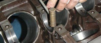
3) insert a special ejector shown in Fig. 101 into the hole in the oil channel;
4) carefully turn the crankshaft clockwise (if you look at the engine from the front) until the ejector foot stops at the end of the liner and install it on the GAZ-51 and ZIM-12 engines parallel to the generatrix of the outer surface of the liner;
5) carefully turn the crankshaft clockwise 180° and push the worn liner out, as shown in Fig. 102;
6) turn the crankshaft counterclockwise so that the ejector foot, being placed in the annular slot between the shaft journal and the liner bed, does not reach the plane of the connector of the block with the bearing cover;
7) place the upper bearing shell (with a hole for lubricant supply) onto the shaft neck so that the joint with the locking protrusion is located on the left side (if you look at the engine from the front), and the locking protrusion itself is located exactly opposite the groove for it in the bearing;
insert several liners with their end without a fixing protrusion into the gap between the shaft journal and the liner bed
in the block, moving it by hand along the shaft journal counterclockwise; in this case, it is necessary to ensure that the liner does not move along the neck - otherwise its fixing protrusion will not fit into the bearing seat;
9) turn the crankshaft counterclockwise until the ejector foot stops at the end of the liner and then, with further careful rotation of the shaft in the same direction, return the liner to its place, making sure that the fixing protrusion on it fits into the groove intended for it in the bed; In this case, the liner should be pressed by hand against the shaft neck at all times;
10) change the lid liner, put the lid in place,
tighten the bolts with a wrench with a controlled torque (see section “General instructions for disassembling and assembling engines” in Chapter IV) and secure them with wire.
To replace the specified liners, liners of the appropriate size for operational repairs must be used or, if they are not available, liners of the same size as those being replaced.
If the replacement earbuds had spacers at the joints, the tone earbuds must be the same size as the ones being replaced; install new ones: in this case, the liners must be without gaskets at the joints.
If necessary, the rear main bearing shells can also be replaced using this method. To prevent oil from flowing through it after replacing the liners, it is recommended that before replacing the cover, replace the right and left sealing gaskets (rubber) in it with new ones and thoroughly clean with wire the small hole in the panel, designed to drain lubricant from the annular groove of the liners into the engine crankcase.
On the front main bearing, it is impossible to replace the liners without removing the engine from the car due to the fact that the pin that fixes the position of the front thrust bearing washer and is pressed into the end of the cover does not allow it to be removed without damaging the gasket of the timing gear cover plate. Damage to this gasket disrupts the seal of the front part of the crankcase or the subsequent installation of the front sealing bracket in place and makes it necessary to replace it with a new one, which cannot be done without removing the engine from the car. As a result of changing deposits
removing the front main bearing inevitably entails removing the engine from the vehicle.
To be able to change the front main bearing shells using the method described above on the GAZ-51, ZIM-12, M-20 and GAZ-69 engines, in the near future it is planned to install the front main bearing cover shown in Fig. 103, with a retractable (sinking) pin inside it.
At the same time, in the sealing bracket of the front part of the crankcase, instead of a threaded hole for bolt 1, securing it to the plate of the timing gear cover and located under the cover (Fig. 104), a smooth hole will be made, and the corresponding hole in the plate will be cut. In this case, bolt I will ... be screwed from the crankcase part (from the side of the bracket) and to access it it will not be necessary to remove the cover of the timing gears, which will significantly reduce the cost of labor and time for changing the shells of the first main bearing.
To remove the new front main bearing cap, you must:
1. Remove the oil sump.
2. Using an L-shaped wrench, unscrew the two bolts 2 (Fig. 104) securing the timing gear cover.
3. Unscrew the bolt securing the sealing bracket to the plate of the timing gear cover from the oil sump side.
4. Unscrew the two screws securing the sealing bracket to the block and remove it.
5. Unscrew and unscrew the two bolts securing the front main bearing cover.
6. Place a thin steel plate (probe) 8-10 mm wide into the gap between the support plate and the front end of the cover so that the plate is against the pin securing the front washer of the thrust bearing, as shown in Fig. 105.
7. Remove the bearing cover so that the locking pin moves all the time along the metal plate.
When the pin passes over the timing gear cover plate gasket, it will, overcoming the resistance of the spring, be pressed inside the hole in the cover and thereby prevent damage to the gasket.
Reinstalling the front main bearing cap after replacing the bearings is done in the reverse order. In this case, it is necessary to pay attention to the installation of the sealing bracket: it must, without deformation of its entirety, fit tightly with its entire plane to the gasket of the plate of the timing gear cover, for which you should, placing gaskets under the bracket, lightly screw it with two screws to the block, then tighten the bracket with three bolts ( first side, and then middle) to the gasket of the timing gear cover plate and only after that finally tighten the two screws securing the bracket to the block.
Crankshaft bearing design
The crankshaft sliding bearing is a composite bearing, containing two metal flat half-rings that completely enclose the crankshaft journal (top and bottom). This part performs several elements:
• Holes (one or two) for passing oil into the oil channels in the crankshaft and connecting rod; • Locks in the form of tenons or grooves for pins for fixing the bearing in the crankshaft bed support or in the lower head of the connecting rod; • Longitudinal groove for supplying oil to the hole (performed only on the liner located on the side of the channel - these are the lower main liner and the upper connecting rod liner); • In shoulder thrust bearings there are side walls (collars) for fixing the bearing and limiting the axial movement of the crankshaft.
The liner is a multilayer structure, the basis of which is a steel plate with an anti-friction coating applied to its working surface. It is this coating that ensures reduced friction and long service life of the bearing; it is made of soft materials and, in turn, can also be multi-layered. The coating of the liner, due to its less softness, absorbs microscopic wear particles from the crankshaft, prevents jamming of parts, the formation of scuffing, etc.
According to their design, crankshaft liners are divided into two main groups:
• Bimetallic; • Trimetallic.
Bimetallic bearings have the simplest design. They are based on a steel strip 0.9-4 mm thick (depending on the type and purpose of the part, main bearings are thicker, connecting rod bearings are thinner), on which an anti-friction layer 0.25-0.4 mm thick is applied. This layer is made of copper-lead-tin (bronze), copper-aluminum, copper-aluminum-tin, aluminum-silicon-lead, aluminum-silicon-lead-tin or other soft alloys with an aluminum and copper content of up to 75%, and tin (which acts as a solid lubricant) up to 25%, may also contain small amounts of nickel, cadmium, zinc and other metals.
Trimetallic liners, in addition to the main antifriction coating, have a coating layer 0.012-0.025 mm thick (12-25 microns), which provides protective properties (fights corrosion and excessive wear of the main layer) and improves the antifriction qualities of the bearing. This coating is made from a lead-tin-copper alloy with a lead content of 92-100%, tin up to 12% and copper not more than 3%.
Also, additional layers may be present in sliding bearings:
• The top protective layer of tin is a pure tin coating with a thickness of only 0.5-1 microns, providing protection against corrosion, grease and contamination during transportation, installation and running-in of the liner; • Bottom protective layer of tin - the same layer applied to the outside of the liner (facing the crankshaft supports or the inside of the connecting rod head); • Nickel sublayer (nickel barrier, gasket) - a thin, no more than 1-2 micron layer of nickel between the main anti-friction coating and the cover layer. This layer prevents the diffusion of tin atoms from the coating layer into the main one, which ensures the constancy of the chemical composition of the main antifriction coating. In the absence of a nickel barrier in the base coating, the concentration of tin may increase, which leads to negative changes in the characteristics of the bearing.
The considered structure of sliding bearings is not a standard; many manufacturers offer their own unique schemes and designs. For example, the main antifriction alloy can be applied to the steel base not directly, but through an additional sublayer of aluminum or copper alloy; the coating layer can have a varied composition, including lead-free, etc.
Repair
Replacing main bearings requires wrench and screwdriver sets and a micrometer. Repair of main liners includes several operations.
- First of all, you need to provide access to the car from below. That is, it should be installed above an inspection hole or on an overpass.
- Remove the negative wire from the battery terminal.
- Next, dismantle the engine sump (this is the easiest way to access; you can start disassembling from above and hang the engine).
- After this, the crankshaft rear oil seal holder is removed from the cylinder block.
- Then remove the camshaft drive cover with the gasket.
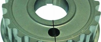
- Then remove the chain from the crankshaft sprocket-pulley.
- Next, you need to mark the relative position of the bearing caps relative to the cylinder block and the connecting rods relative to their caps.
- Then, using a 14mm wrench, unscrew the nuts of the connecting rod cover and dismantle it with the liner.
- These operations are repeated for all connecting rods.
- When completed, the lids are moved up.
- Then the main bearings are removed from the caps and connecting rods.
- Next, use a 17 wrench to unscrew the bolts of the crankshaft main bearing caps.
- First, remove the cover of the last one.
- It opens access to the thrust half-rings in the grooves of the rear crankshaft support. They are removed by pressing on the ends with a thin screwdriver.
- These operations are repeated for the remaining bearing caps. In this case, you need to hold the crankshaft. It should be noted that the covers are designated by numbers, and the countdown is from the toe of the crankshaft.
- It is then removed from the crankcase.
- First, the connecting rod bearings are removed, and then the crankshaft main bearings.
- The crankshaft should be inspected for damage. If they are present, the part is changed.
- The connecting rod and main caps are also examined by measuring with a micrometer. The obtained data are correlated with the tabular ones.
- If necessary, parts are polished. In this case, you will need to measure them to calculate the repair size of the liners.
- The crankshaft is cleaned by washing with kerosene and blowing out the cavities.
- Then new bearing shells are installed.
- Thrust half rings are mounted in the grooves of the fifth bearing bed with grooves towards the crankshaft.
- Next, check the gap between these parts. The normal value is considered 0.06-0.26 mm. If it is more than 0.35 mm, use rings of increased thickness.
- The crankshaft is installed in the block, having previously been lubricated with oil.
- Then install the bearing caps and check the freedom of rotation of the crankshaft.
- Connecting rods, liners and covers are installed on it.
- Then the oil pan is installed.
- After this, install the crankshaft holder with the rear oil seal.
- Finally, the remaining parts are installed.
- Finally, the tension of the timing chain, alternator belt and ignition timing are adjusted.
Marking features
If bearing parts are worn or damaged and the correct crankshaft clearance cannot be obtained, the situation can be improved by selecting new bearings. If the connecting rods have been bored, then they must be equipped with parts of the corresponding repair sizes of the connecting rod bearings. Usually the selection is entrusted to specialists.
When choosing new connecting rod bearings, they are guided by color markings - you need to look at those parts that were removed from the car. If the elements of old bearings do not have color markings, then look for them on the lower heads. There you need to see a mark in the form of a number - this is the class of the bearing. They also check the letter marks on the crankshaft - they determine the dimensions of the connecting rod journals.
To navigate the bearing selection map, use the markings on the cylinder block. For example, C3 says that you need to install a yellow and green liner. Moreover, any of them can be installed in a lid or in a bed. When selecting new bearings, use the identification color card for marking the connecting rod bearings. So, if you find a letter on the connecting rod journal and a number on the connecting rod (for example, D4), then according to this map you need a blue bearing. Naturally, you need to remember that colors may be different for different engines.
How to make an insert in a work book
Tractor T-16 Design, principle of operation, characteristics and repair of tractors T-16, T-16 M and T-16 MG
As mentioned above, the insert is issued only if the main document is completed, and both sections on work can end, and information about awards.
That is, in such a situation, this aspect is not paramount; the liner is started accordingly, taking into account the rules stipulated in Resolution No. 225.
Issuance procedure
Each form of a labor book and its insert purchased by an enterprise is registered in a special journal; accordingly, when the form is issued to an employee, an entry is made in the specified journal, the form of which is approved by Resolution No. 69.
Although the employee himself can purchase the insert, this form will still be subject to registration in the journal.
Rules for registration and maintenance
Clause 38 of Resolution No. 225 states that the insert is maintained in accordance with the same rules that are established when maintaining a work book, but, nevertheless, taking into account some nuances, as well as the absence of separately developed rules, many questions arise when entering those other data .
Where to put a stamp indicating that the insert has been issued?
In particular, paragraph 39 of Resolution No. 225 establishes the rule for the mandatory insertion of a stamp on the establishment of the insert, but at the same time, the place of the stamp is not specified, and therefore, according to established practice, the mark on the establishment of the specified document is entered in the upper right corner of the title.
That is, in the absence of a stamp, it is quite acceptable to make a manual entry stating that the insert is issued, indicating the date of establishment, number and series of the specified document.
A sample insert record is as follows: Insert issued: Series. Number. Date of.
An illustrative example:
Title registration
The design of the title page of the insert is not much different from the same procedure when filling out a book about work.
Almost the same data is entered, namely:
- surname, name, patronymic of the employee;
- Date of Birth;
- education;
- speciality.
But, nevertheless, there are some differences.
That is, if there was a previous change of name, then the insert indicates new data, the same applies to newly acquired education, if available and specialization.
Example (filling sample):
Date of completion
After filling out the above-mentioned fields, the date of filling out the insert is indicated, which, accordingly, is also indicated as the real one, and not the one indicated in the work book.
That is, the date the insert was created will correspond to the date of the entry made for the first time in the insert.
Are stamps needed?
Accordingly, after entering the date, the personnel employee who fills out the insert must put his signature and also put the company’s seal, by analogy with filling out the main document - a work book, that is, there are no distinctive features in this aspect.
Numbering of entries
After filling out the title page, an entry is made, the numbering of which will not correspond to the number 1, taking into account the beginning of a new document, but quite the opposite, because the insert is a continuation of the work book, accordingly, the numbering continues from the next number, which was indicated in the work book.
How to sew?
As a rule, the liner is attached to the work book in several ways, since not everyone knows whether it needs to be sewn in, given that this rule is not established at the legislative level.
In particular, in some cases, it is commonplace to use a large paperclip for attachment or even store them together, although it is still recommended to sew in the insert, of course, after filling out this document.
This procedure should be carried out so that the insert does not get lost, because the paperclip may come off, and then confusion in the documents will be inevitable.
Main liners
Engine main bearings are designed to house the engine crankshaft in the engine block and allow the crankshaft to rotate.
What are engine main bearings used for?
Engine main bearings are essentially plain bearings and ensure reliable rotation of the crankshaft under significant speeds and loads. The design of the crankshaft and bearings provides for the supply of oil to the interface between the bearing and crankshaft journals in order to form an oil film and reduce friction.
The liner itself remains motionless relative to the engine, since it is fixed in places specially prepared for this, called beds. Additionally, a special anti-friction coating is applied to the surface of the liner.
How often to change engine main bearings?
The design of the main engine bearings remains traditional over time - this is a plain bearing, which is a bent metal sheet of a certain radius with an anti-friction coating applied.
Main bearings work in very difficult conditions. Therefore, very serious requirements are placed on the liners, as well as their installation. Theoretically, the durability of the liners is comparable to the service life of the engine, i.e. more than 200 thousand km. The need to replace the main bearings arises when they are worn out (usually due to insufficient lubrication or poor-quality material). In case of insufficient lubrication, due to an increase in the friction force between the liner and the journal, the liners may be torn from their place in the cylinder block, and the block itself may be damaged.
The need to replace the main bearings also arises when repairing (grinding) the crankshaft journals, since in this case the size of the journals changes. In this case, it is necessary to install inserts of a different size. Poor engine assembly, non-compliance with manufacturing technology and dimensions of individual parts, engine overheating and changes in its geometric parameters can also lead to wear or damage to the main liners.
Why does this happen and how to avoid it?
- The lubricant was too viscous or there was too little of it. Abrasive got into the lubricant and disrupted the smooth running. Lubricant cleanliness is one of the key parameters for preventing any breakdown; it is better to change it regularly every 60-80 thousand km. mileage
- The motor was constantly operating in overload mode. You should not constantly “strain” the engine at high speeds and drive the car for a long time without slowing down.
- When installing previous bearings, the interference was too low. Check everything yourself, tighten the bolts well, it is better to use special equipment.
Why do you need to replace half rings and when is it necessary?
Half rings are consumables and are subject to wear. When they wear out, the crankshaft begins to move horizontally, which accelerates the wear of the half rings. Ultimately, the half rings become completely unusable (erased) and the crankshaft loses all fixation, creating a threat, first of all, to the entire piston group. In addition, the crankshaft can grind the cover that covers it and render the support bearings unusable. These parts are cast together with the block, which indicates a high probability of replacing the latter. To prevent this, it is necessary to carry out timely diagnostics of faults and, if necessary, change the half rings.
Diagnostics are performed after 120 thousand kilometers and begin with an external inspection of the engine. The presence of an oil leak is the first, but not the main sign. The fact is that when play appears, the crankshaft can squeeze out the oil seal, which will very quickly lead to a leak of engine oil. However, oil leaks do not always occur precisely for this reason. It is quite possible that the oil seal simply became unusable due to natural wear and tear.
Take the installation tool and, resting it on the generator, try to shake the crankshaft pulley. The permissible axial play should not exceed 0.35 mm. Also, have someone press the clutch pedal. If the crankshaft is pushed forward, then this is the most obvious sign of a malfunction of the crankshaft half rings.
Before carrying out the replacement, purchase new engine oil, as this may be an excellent opportunity to replace it, the oil pan gasket and the half rings themselves.
Work order
1. Place the car on a pit or overpass and prevent it from moving.
2. Unscrew the engine protection and remove it. Drain the engine oil.
3. Unscrew all bolts securing the oil pan and remove it along with the gasket.
4. Unscrew the bolts for securing the main bearing cap and remove it.
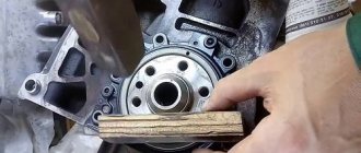
5. Install the new half rings so that its ends rest against the ends of the old one. To make the task easier, move the shaft with a screwdriver.
6. Push out the old element using the new one. The new part should fit in absolutely freely.
That's all. This completes the replacement of the crankshaft half rings. Reassemble all components in reverse order. When installing a new pan gasket, be sure to treat it with a sealant that can withstand high temperatures. After assembly, fill in new oil.
Replacing crankshaft bearings
Remove the hood (see Replacing the hood) and the battery. Drain the oil (see Changing the oil). Drain the coolant (see Replacing the coolant). We remove the radiator together with the thermostat (see Replacing the radiator and Replacing the thermostat).
Remove the carburetor (see Replacing the carburetor). Remove the fuel pump (see Replacing the fuel pump). Remove the ignition distributor (see Replacing the ignition distributor). Having sketched the connection order, we disconnect the hoses and wires from the engine, lighten the cylinder block, for which we remove the cylinder head (see Replacing the cylinder head gasket). We remove the generator (see Removing the generator). Remove the starter (see Replacing the starter). Remove the coolant pump (see Replacing the coolant pump). We unscrew the upper or lower nuts securing the engine support cushion (see Replacing the engine support cushion). We unscrew the bolts securing the clutch housing to the engine. We fasten the cables of the lifting device to the block and lift it. By placing a jack under the gearbox and slightly rocking the block, we disconnect the block and the clutch housing.
We install the cylinder block on the stand. Remove the clutch (see Replacing the pressure plate assembly and clutch release bearing). Remove the pulley, camshaft drive cover, oil pump drive chain and gear (see Replacing the camshaft drive chain). Remove the auxiliary drive shaft (see Replacing the auxiliary drive roller). Remove the flywheel and the rear crankshaft cuff holder (see Replacing the rear crankshaft cuff). Using a 10mm wrench, unscrew the fourteen bolts securing the oil pan to the cylinder block...
...and remove it along with the sealing gasket.
Remove the oil pump (see Removing and disassembling the oil pump). Using a 14mm socket, unscrew the two nuts securing the connecting rod cover...
...and remove the connecting rod cover.
Using the wooden handle of the hammer against the connecting rod, we push the piston out of the cylinder.
Similarly, remove the remaining three pistons. Using a 17mm socket, unscrew the two bolts securing the crankshaft main bearing cover...
...and remove it.
In the same way, remove the remaining four main bearing caps. They are marked with marks corresponding to their serial number (count from the toe of the crankshaft). On the last (fifth) cover there are two marks stamped, spaced along the edges.
Marks on the main bearing caps.
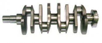
We remove the crankshaft.
From the grooves in the bed of the fifth main bearing, we remove two half rings of the crankshaft thrust bearing.
The steel-aluminum liners installed in the beds of the 1st, 2nd, 4th and 5th main bearings have a groove. The shell of the 3rd bearing does not have a groove (similar to the shells installed in the main bearing caps).
We disassemble the crankshaft (see Disassembling the crankshaft). We take out the old main bearing shells. We wash the cylinder block and crankshaft in diesel fuel or kerosene. We blow out their internal cavities and oil channels with compressed air. We wipe the seats of the main bearings with a napkin and install new liners of the appropriate category (nominal or repair). Lubricate the main and connecting rod journals of the crankshaft with engine or transmission oil and install the shaft into the block. We install the main bearing caps with new bearings of the category corresponding to the crankshaft journals installed in them in accordance with the marks. Tighten the cover fastening bolts with a torque wrench (see Appendices).
Checking the rotation of the crankshaft. It should be light and smooth, without jamming or play. We install new steel-aluminum liners into the lower heads and connecting rod caps (see Replacing the piston). Lubricate the piston, rings and cylinder walls with engine oil. We compress the rings with a special device and turn the piston with the “P” mark towards the toe of the crankshaft. With light blows of the wooden handle of a hammer on the bottom of the piston, we press it into the cylinder.
We put on the connecting rod cover and tighten the bolts with a torque wrench (see Appendix). Further assembly of the engine is carried out in the reverse order of disassembly.
Geometry
Naturally, the sizes of connecting rod bearings are different for different internal combustion engines. The most basic parameter is the oil gap. It is equal to the difference between the inner diameter of the liner and the diameter of the shaft. Another important indicator is the size of the oil gap. If the gap is very large, then the oil flow increases, which reduces the heating of the bearing. But oil also causes uneven load distribution, which increases the likelihood of bearing failure due to fatigue. A large gap will result in operating noise and vibration. A small gap will cause the engine oil to overheat and reduce viscosity.
The landing tension is needed to ensure a reliable fit of the VAZ connecting rod bearing in its socket. Reliably and firmly seated bearings are in even contact with the surface of the seat - this will prevent the possibility of bearings moving during operation. Effective heat dissipation is also ensured.
Installation Features
A set of main liners is installed in a fixed position in special places called beds. The need for a fixed installation is due to two factors. First, some liners have oil holes and need to be aligned with similar channels in the beds. Secondly, this makes it possible to ensure friction of parts on surfaces prepared for this.
Boring
All connecting rods are removed after sequentially checking the clearances, and the crankshaft is also dismantled and ground. Boring is possible only on special equipment - a centripetal, which is rarely found among ordinary car owners. Therefore, here you will need to contact specialists. After grinding, the crankshaft liners of the appropriate size are selected. Here you cannot do without a tool such as a micrometer and trying on selected elements. Next, all crankshaft parts are installed in the reverse order and the caps on the main bearings are screwed on.
It is worth noting some features of the reverse installation of connecting rods and bearings. The latter are pre-lubricated with oil, and the lids must also be screwed on. Compared to the preparatory work carried out, installation takes much less time. At the same time, we should not forget about the operation of the crankshaft, which is characterized by high loads, as well as its high cost. Everything possible must be done to increase the period of operation. The main role here is played by grinding carried out at the appropriate time. This procedure ensures the smoothness of the necks and prepares them for further use.
Installation procedure
Most often, these elements are installed in auto repair shops, where experienced specialists work. However, if a person has certain repair skills and is good with tools, then you can try to install the crankshaft elements yourself. To do this, you must follow the following procedure:
- The gap between the shaft and the liner is checked. Plastic wire is used here. It is tightened with a force of 51 newton per meter and after that the existing gap is determined by the degree of flattening of the wire. If it is larger than the nominal value, then the liner needs to be replaced.
- All connecting rods are removed from the racks, the crankshaft is dismantled and bored. Then the repair element is selected. These procedures should be performed on a centripetal, and it is also important to have a micrometer.
- After selecting the element, the crankshaft is reinstalled. The components are inserted into their seats and the main bearing caps are screwed on.
- The crankshaft and connecting rods are put back. The inserts are lubricated with oil and their covers are screwed on. As a result, the process is completely completed, the liners will work for a long time.
Direct installation of such elements takes a relatively short amount of time compared to preparatory measures and additional work. This means that with a strong desire and appropriate skills, anyone can insert earbuds on their own.
This is interesting: The best diesel engine for a passenger car
Popular on the site
17 Dec
Auto News
2 759
2022 Kia Sportage. When will the new body appear in Russia?
On the page are the first details about the new Kia Sportage body of the 2021 model year, possible configurations and prices, release date in Russia, photos, technical specifications and video test drive of the new model.
28 Jan
Automotive software Repair/operation manuals
941
Nissan Qashqai 2 2.0 — Do-it-yourself replacement of spark plugs (photo report)
Replacing spark plugs on a modified MR20DD Qashqai 2 engine ( J11
) 2.0 l. according to the regulatory deadlines, it should be carried out over a mileage of 30,000 km or once every 24 months. Since this Qashqai, the second generation, was released not so long ago, it has a different, improved engine (a naturally aspirated engine with an aluminum cylinder block with a high compression ratio), unlike its counterparts, it uses more modern, iridium spark plugs.
18 Dec
Electronics and equipment Electrical circuits
894
2022 Jeep Grand Cherokee. Release date of the new body in Russia
Development of the fifth-generation 2022 Jeep Grand Cherokee began with the creation of a new platform. The basis was taken from the Giorgio “trolley”, currently used on the Alfa Romeo Stelvio and Giulia.
16 Dec
Repair Cooling system
651
Toyota Avensis - DIY radiator replacement
Before we begin the replacement, let's say a few words about the new radiator and the tool. The tools you will need are: several screwdrivers, a standard set of keys and an empty container for antifreeze.
29 Dec
Tuning Car tuning
634
Mansory Body Kit makes a Rolls-Royce Cullinan look good in white
Unlike Bentley, which has made several versions of its big boy, Rolls-Royce is in no hurry to fix anything. But fortunately, many clients are wealthy enough to afford a complete makeover. The Mansory body kit actually came out much earlier, at the 2022 Geneva Motor Show.
04 Feb
Auto News
590
2022 Genesis G90. Everything you need to know
The Genesis G90 may be the best luxury bargain to date, offering flagship levels of refinement and performance at a significantly lower price than its more established competition. For 2022, the G90 will receive its first update since the sedan's flagship debuted as a 2017 model, and it includes significant styling updates but only minor interior and driving changes.
24 Dec
Repair Electronics and equipment
575
Symptoms of a faulty engine control unit (ECU)
The engine control unit (ECU), also called the engine control module or transmission control module, is one of the most important components found on almost all modern vehicles.
09 Jan
Articles Engine and its components Ignition system
575
Glow plug relay - how to check its functionality? + Video
Each car has its own glow plug relay circuit. It, like every part, can fail and will have to be replaced. To deal with the rather serious question of how exactly to make a replacement, you need to start with the basics.
10 Feb
Repair Electronics and equipment
559
Skoda Karoq - Unable to register with Skoda Connect
The vehicle cannot be registered when using ŠKODA Connect services. There is no need to update data in the mobile app or on the ŠKODA Connect internet portal.
08 Feb
Reviews / Test drives Articles
558
Best Spark Plugs for Your Car (Review and Buying Guide)
A spark plug is a device or component in your car that is there to supply current from the ignition system to the combustion chamber of the engine. It is used to ignite compressed air or fuel with an electric spark when combustion pressure is present in the engine.
What are plain bearings
To better understand why engine bearings need to be tightened to a certain torque, let's take a look at the functions and purpose of these elements. Let's start with the fact that these sliding bearings interact with one of the most important parts of any internal combustion engine - the crankshaft. In short, the reciprocating motion of the piston in the cylinder is converted into rotational motion precisely thanks to the connecting rods and crankshaft. As a result, torque appears, which is ultimately transmitted to the wheels of the car.
The crankshaft rotates constantly, has a complex shape, experiences significant loads and is an expensive part. To maximize the service life of the element, connecting rod and main bearings are used in the crankshaft design. Taking into account the fact that the crankshaft rotates, as well as a number of other features, conditions are created for this part that minimize wear.
In other words, the engineers abandoned the decision to install conventional ball or roller bearings in this case, replacing them with main and connecting rod bearings. Main bearings are used for the crankshaft journals. The connecting rod bearings are installed at the junction of the connecting rod with the crankshaft journal. Often, main and connecting rod bearings are made according to the same principle and differ only in the inner diameter.
For the manufacture of liners, softer materials are used compared to those from which the crankshaft itself is made. The liners are also additionally coated with an anti-friction layer. Lubricant (motor oil) is supplied under pressure to the place where the liner is connected to the crankshaft journal. The specified pressure is provided by the oil pump of the engine lubrication system. In this case, it is especially important that there is the required clearance between the crankshaft journal and the plain bearing. The quality of lubrication of the rubbing pair, as well as the engine oil pressure in the engine lubrication system, will depend on the size of the gap. If the gap is increased, then the lubricant pressure decreases. As a result, rapid wear of the crankshaft journals occurs, and other loaded components in the internal combustion engine also suffer. In parallel with this, a knock appears in the engine.
We add that a low oil pressure indicator (in the absence of other reasons) is a sign that the crankshaft needs to be ground, and the engine liners themselves need to be changed taking into account the repair size. For repair liners, an increase in thickness of 0.25 mm is provided. As a rule, there are 4 repair sizes. This means that the diameter of the repair liner in the last size will be 1 mm higher. less compared to standard.
We also recommend reading the article about when and why you need to bore the crankshaft. From this article you will learn about what engine crankshaft grinding is, why this procedure is necessary and how it is performed.
The plain bearings themselves consist of two halves, in which special locks are made for proper installation. The main task is to create a gap between the shaft journal and the liner, which is recommended by the engine manufacturer.
As a rule, a micrometer is used to measure the journal; the inner diameter of the connecting rod bearings is measured with a bore gauge after assembly on the connecting rod. You can also use control strips of paper for measurements, use copper foil or control plastic wire. The gap at the minimum mark for rubbing pairs should be 0.025 mm. An increase in the gap to 0.08 mm is a reason to bore the crankshaft to the next repair size
Note that in some cases the liners are simply replaced with new ones without boring the crankshaft journals. In other words, it is possible to get by only by replacing the liners and obtaining the desired gap without grinding. Please note that experienced specialists do not recommend this type of repair. The fact is that the service life of the parts at the mating point is greatly reduced, even taking into account that the gap in the rubbing pair corresponds to the norm. The reason is considered to be microdefects that still remain on the surface of the shaft journal if grinding is not performed.
Questions about choosing and replacing crankshaft liners
When selecting sliding bearings, it is necessary to take into account the engine model, wear of associated parts and the presence of repair liners. As a rule, liners are made for one model range or even one engine model, so they cannot be replaced with parts from another engine (with rare exceptions). Also, you cannot use liners without taking into account the wear of the crankshaft journals, otherwise the repair will result in even bigger problems.
Before choosing the repair size of bearings, you need to determine the wear of the crankshaft journals and other associated parts (beds, connecting rod heads, although they are less subject to wear). Usually, the wear of the journals occurs unevenly, some of them wear out more intensively, some less, however, for repairs, a set of identical liners is purchased, so all journals must be ground down to the same size. The choice of the value to which the crankshaft journals will be ground depends on the availability of bearings of certain repair sizes suitable for this particular engine. For engines with low mileage, repair sizes of +0.25 or +0.5 are selected; for engines with significant mileage, it may be necessary to grind down to repair size +1.0; in older engines, even more - up to +1.5. Therefore, for new engines, liners are usually produced in three or four repair sizes (up to +0.75 or +1.0), and for old engines you can find liners up to +1.5.
The repair size of the crankshaft liners must be such that when assembling the engine, a gap remains within 0.03-0.07 mm between the crankshaft journal and the bearing surface. With a smaller gap, there is a high risk of jamming; with a larger gap, the crankshaft runout increases, the wear rate of parts and the overall noise of the power unit increases.
With the correct choice of sleeve bearings for the crankshaft, the engine, even with high mileage, will operate efficiently and effectively in various modes.
Why does the connecting rod bearing rotate?
The bearings of the connecting rods and crankshaft of the internal combustion engine are plain bearings that must be generously lubricated in order to perform their functions. The crankshaft journals and connecting rod bores fit tightly without play or gaps, but thanks to lubrication, the friction force of the mating pairs is minimal.
Rotation of the connecting rod bearings and crankshaft requires immediate repair. You cannot operate a car with such damage to the engine, because further destruction of parts or components of the internal combustion engine may occur. This breakdown can be determined by ear; a knocking sound of the crankshaft and connecting rod can be heard.
Liners, also known as sliding bearings, are placed in places called bearing beds. The inserts must be fixed. If the liners have holes, they must be aligned with the holes in the mating part.
Did you know that the type of locking and overtension of the differential is responsible for the cross-country ability and controllability of the car?
The main reasons for rotation of the liners:
- The inserts were not fixed sufficiently;
- the inserts are stuck.
The crankshaft rotates relative to the liners, the surface of which is protected by antifriction (anti-rubbing) material. To prevent the liners from shifting and turning along with the engine crankshaft, they are held in place by special antennae. They are also installed in tension, which were calculated by the manufacturers.
The greater the load on the crankshaft, the less the oil film (layer, cushion) is created. And if there is still excessive vibration, then the oil protective layer is destroyed and the friction force increases sharply, which makes it more and more difficult for the liner to stay in bed; the antenna designed to protect against rotation cannot hold the liner.
As a rule, the reason for rotation of the bearings is the lack of lubrication. For lubrication, there are holes on the main bearings, and grooves on the connecting rod bearings. If these oil supply channels are clogged, the holes and channels are completely or partially clogged, the friction force of the rubbing parts increases, and the effect of oil starvation appears. Due to the lack of lubrication, the liner-crankshaft pair becomes very hot. During heating, the rubbing parts stick to each other. After such welding, the liners begin to rotate.
Types and sizes
VAZ crankshaft liners act as protective elements that prevent premature wear of mating parts. Depending on their location, they are divided into two types: main and connecting rod. The latter, as mentioned earlier, are located on the journals of the shaft, the main ones are located on the crankshaft at the point where it passes through the internal combustion engine and have a similar purpose. Different types of power devices require the use of appropriate elements; first of all, the internal diametrical size must be selected.
Repair parts both differ from each other and have significant differences compared to the new elements that are equipped with new cars at factories. The parameters differ by at least a quarter of a millimeter; all subsequent options go through a similar step.
How and with what force to tighten the connecting rod and main bearings
The internal combustion engine structurally has a large number of associated parts, which experience significant loads during operation of the internal combustion engine. For this reason, assembling a motor is a responsible and complex operation, for the successful implementation of which the technological process must be followed. The performance of the entire power unit directly depends on the reliability of fixation and the accuracy of fit of individual elements. For this reason, an important point is the accurate implementation of the calculated interfaces between mating surfaces or friction pairs. In the first case, we are talking about attaching the cylinder head to the cylinder block, since the cylinder head bolts must be pulled with a strictly defined force and in a clearly designated sequence.
We also recommend reading the article on how to tighten cylinder head bolts. From this article you will learn about the cylinder head tightening torque, the tightening sequence, as well as various nuances during this operation.
As for loaded rubbing pairs, increased demands are placed on the fixation of connecting rod and main plain bearings (main and connecting rod bearings). After engine repair, during the subsequent assembly of the power unit, it is very important to maintain the correct tightening torque of the main and connecting rod bearings of the engine. In this article we will look at why it is necessary to tighten the bearings with a strictly defined force, and also answer the question of what is the tightening torque for the main and connecting rod bearings.
Connecting rod bearing
Connecting rod bearings are designed to reduce friction and wear in the moving connecting rod - crankshaft journal. Tractor connecting rods mainly use plain bearings.
Connecting rod bearings have thin-walled steel liners filled with anti-friction alloy. For carburetor engines, a copper-non-nickel sublayer is applied to the steel strip, on top of which a thin layer of babbitt is poured. An oil channel runs through the body of the connecting rod along its entire length, through which oil is supplied under pressure from the lower head of the connecting rod to the upper one. A bushing is pressed into the lower part of this channel, metering the flow of oil into the upper head of the connecting rod.
Connecting rod bearings are generally plain bearings. Needle bearings and rolling bearings are used only for the smallest engines. For most diesel engines (except for large low-speed ones), the connecting rod rod and piston head are made in one piece.
| Connecting rod of a single-row trunk engine assembled. |
The connecting rod bearings are lubricated with oil, which is supplied under pressure from a hole in the crankpin of the crankshaft.
Connecting rod bearings are bored on a lathe or on special devices (Fig.
The connecting rod bearing is lubricated and cooled by oil coming from the main bearings through the channels of the crankshaft. Through the holes in the lower liner and through channel a in cover 1, oil flows into the channel of the lower head of the connecting rod and through bushing 3, sealed with ring 4, into the channel of the main connecting rod rod. From bushings 7 and 8, through holes in the upper heads of the connecting rods, oil flows to cool the pistons.
The connecting rod bearing is lubricated and cooled by oil supplied from the main bearings through oil passages in the crankshaft. Part of the oil is used to cool the piston head.
Connecting rod bearings are made with thick-walled or thin-walled liners with Babbitt or lead-bronze filling. The bearing shells are secured against rotation and axial displacement by pins or protrusions and grooves in the cover. In order for the inner surface of the liner to maintain the correct cylindrical shape necessary for normal operation of the bearing, the lower head of the connecting rod must have sufficient rigidity. Therefore, the lower heads are usually made massive, with stiffening ribs and smooth transitions to the rod.
Connecting rod bearings have thin-walled steel liners filled with anti-friction alloy. For carburetor engines, babbitt is used, and for diesel engines, lead bronze is used, which is applied in a thin layer over a lead-tin alloy. To lubricate the piston pin, a hole is made in the upper head of the connecting rod, through which oil passes from the internal cavity of the piston. In the body of the connecting rod, along its entire length, there is a channel through which oil is supplied under pressure from the lower head of the connecting rod to the upper one. The YaMZ-236 engine has a bushing pressed into the lower part of this channel that meteres the flow of oil into the upper head of the connecting rod.
Connecting rod bearings must allow the connecting rod to rotate relative to the crankshaft with minimal friction and wear. They work in more difficult conditions than indigenous people. This is explained primarily by their uneven load. The upper half of the connecting rod bearing is subject to a short but significant load from gas forces, and the lower half is subject to a longer load from the inertial force of translationally moving and rotating masses. In addition, supplying lubricant to the connecting rod bearings is more difficult than to the main bearings.
| Staggering and wear of the crankshaft main bearings. |
All connecting rod bearings are disassembled for inspection.
The connecting rod bearings are scraped along the journals of the crankshaft, for which they are lubricated with a thin layer of paint (blue or lamp black diluted in oil), and the connecting rod bearing with adjusting shims is tightened.
Repair the connecting rod bearing and the bushing of the connecting rod upper head.
Types of earbuds
In addition to the main ones, there are connecting rod bearings. It is necessary to distinguish them.
With the exception of the middle liner, they have ring grooves. The middle support parts are wider than the others. There are 10 such liners in total: 4 with a groove and 6 without. Main liners with grooves and one without are installed in the third place in the cylinder block body. The rest are mounted in the main covers.
The connecting rod bearings are smaller in diameter. They are the same size, therefore interchangeable, and do not have ring grooves. An insert with a hole is mounted in the connecting rod, and without it in the cover.
How to determine the wear of the crankshaft liners and help the mechanism?
When repairing an engine, the question very often arises of how to determine the wear of the crankshaft liners and their next repair size (which they will have after the upcoming boring). As a rule, a micrometer is used for measurements (measures linear dimensions), but this can be calculated visually with sufficient accuracy. The possibility of further boring the crankshaft is immediately assessed.
Replacement is required almost immediately if the crankshaft bearings are rotated. The loud knocking of the mechanism and the constant attempts of the engine to stall will tell you this, sometimes the journals jam, then you definitely won’t be able to drive further. In all other cases, a thorough inspection must be carried out, and if wavy grooves that can be felt with your hands are observed on the journals, the crankshaft must be bored and inserts of the appropriate repair size must be installed.
Operating principle
There are many rotating elements used in the design of cars. The ease of their rotation is ensured by the use of bearings. The most heavily loaded rotating part of the engine is the crankshaft. Therefore, it is also mounted on bearings, and plain bearings are most often used. Modern parts of this type are represented by steel sheets with anti-friction coating. These are the main liners.
Causes of failure
Structural damage and wear during operation are the most common reasons for replacing parts. Despite the regular supply of lubricant and careful operation of the motor, this process is inevitable. Over time, the surface of the journals becomes thinner, the free space between them becomes larger, because of this the crankshaft acquires free movement, the oil pressure decreases and, as a result, its supply decreases. All this causes premature failure of the entire engine system.
Scrolling is the second reason for repair work. Many people have heard about this or dealt with this problem on their own, but not all car owners know why this situation arises. Connecting rod bearings have thin plates that fit into a special bed. In this case, small protrusions are placed along the entire outer surface of the half rings; they should come into contact with the front part of the block, as is the case in new motors. Some conditions reduce the resistance of the antennae in relation to the liner; it sticks to the crankshaft journal and rotates. In such a situation, engine operation stops. It is worth noting the most common reasons for its development:
- the operation of the motor is associated with constant exceeding of the established loads;
- the lubricant has too liquid a structure;
- bearing caps are installed with low interference;
- lack of oil, its excessive viscosity or the presence of abrasive compounds in the composition.
Causes of wear
As mentioned above, when the engine is running, each main liner of the engine is constantly exposed to a frictional force, tending to displace it from its original location. In the original state of a working engine, the strength of the parts is calculated with a margin in order to withstand such loads. For power units up to 200 hp. With. The stress on the liner ranges from 0.1 to 1 kgf. The magnitude of its force is proportional to the load at a constant coefficient of friction.
In addition, the main liners are protected by the fact that they operate in liquid friction mode. This is ensured by the use of oil, which creates a film between the shaft journal and the working surface of the liner. In this way, the parts in question are protected from direct contact and a minimum friction force is achieved. The formation of an oil film is determined by the speed of mutual movement of the rubbing parts. The best online casinos in Russia: Honest rating of TOP 10 casinos at the beginning of 2022. As it increases, the hydrodynamic friction regime increases. This term refers to an increase in the efficiency of pulling the film into the gap and an increase in its thickness as a result. However, as the speed of the parts increases, the amount of heat generated during friction also increases, and, consequently, the oil temperature increases. This leads to its liquefaction, resulting in a decrease in film thickness. Therefore, for optimal operation it is necessary to achieve a balance between the processes considered.
If the integrity of the oil film is damaged, the friction coefficient increases. As a result, the cranking torque generated by the crankshaft increases even under constant load.
However, sometimes the opposite situation occurs when increased loads for some reason lead to a decrease in the thickness of the oil film. Also, as a result of this, the temperature increases, especially in the friction zone. As a result, the lubricant dilutes, further reducing the thickness.
These processes can be interconnected and manifest together. That is, one of them may be a consequence of the other.
Therefore, the cranking torque is significantly influenced by the viscosity of the oil. The relationship between these factors is directly proportional, that is, the higher it is, the greater the friction force. In addition, with high viscosity, the oil wedge increases. However, if the viscosity is excessive, the oil does not flow into the friction zone in sufficient volumes, as a result of which the thickness of the oil wedge decreases. As a result, the effect of oil viscosity on bearing rotation cannot be determined unambiguously. Therefore, another property of this material is taken into account: lubricity, which is understood as the strength of its adhesion to the working surface.
The friction coefficient is determined by the roughness and accuracy of the geometry of the contacting surfaces, as well as the presence of foreign particles in the lubricant. In the case of the presence of particles in the lubricant or surface irregularities, the film is disrupted, as a result of which a semi-dry friction mode appears in some areas. Moreover, these factors manifest themselves most intensively at the beginning of the vehicle’s operation, when parts are running in, so rubbing parts are especially sensitive to overloads during this period.
In addition, the crankshaft main bearings rotate due to insufficient force holding them in place. It may be due to improper installation or be a consequence of wear as a result of the influence of the turning torque.
How to tighten main bearings and connecting rod bearings
So, taking into account the above, it becomes clear that the tightening torque of the main and connecting rod bearings is extremely important. Now let's move on to the assembly process itself.
- First of all, molar liners are installed in the bed of the molar necks. Please note that the middle liner is different from the others. Before installing the bearings, the preservative lubricant is removed, after which a little motor oil is applied to the surface. After this, the bed covers are placed, after which the tightening is carried out. The tightening torque should be that recommended for the specific model of the power unit. For example, for engines on the VAZ 2108 model, this figure can be from 68 to 84 Nm.
- Next, the connecting rod bearings are installed. During assembly, it is necessary to accurately install the covers in place. The specified covers are marked, that is, their arbitrary installation is not allowed. The tightening torque of the connecting rod bearings is slightly less compared to the main bearings (the indicator ranges from 43 to 53 Nm). For Lada Priora, the main bearings are tightened with a torque of 68.31-84.38, and the connecting rod bearings have a tightening torque of 43.3-53.5.